Table of Contents
Advertisement
Quick Links
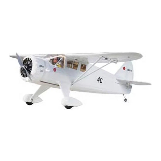
EP ARF
SPECIFICATIONS
Wingspan:
52.5 in
[1335mm]
441 in
2
Wing Area:
[28.4 dm
WARRANTY
Great Planes
®
Model Manufacturing Co. guarantees this kit to
be free from defects in both material and workmanship at the
date of purchase. This warranty does not cover any component
parts damaged by use or modification. In no case shall Great
Planes' liability exceed the original cost of the purchased kit.
Further, Great Planes reserves the right to change or modify this
warranty without notice.
In that Great Planes has no control over the final assembly or
material used for final assembly, no liability shall be assumed nor
accepted for any damage resulting from the use by the user of
the final user-assembled product. By the act of using the
user-assembled product, the user accepts all resulting liability.
If the buyer is not prepared to accept the liability associated
with the use of this product, the buyer is advised to return
READ THROUGH THIS MANUAL BEFORE STARTING CONSTRUCTION. IT CONTAINS IMPORTANT
INSTRUCTIONS AND WARNINGS CONCERNING THE ASSEMBLY AND USE OF THIS MODEL.
© 2011 Hobbico
®
, Inc.
®
Weight:
5.25– 5.75 lb
[2380– 2610 g]
Wing
27– 30 oz/ft
2
Loading:
]
[82– 92 g /dm
INSTRUCTION
Length:
Radio:
Motor/ESC/Prop:
2
2
]
this kit immediately in new and unused condition to the
place of purchase.
To make a warranty claim send the defective part or item to
Hobby Services at the address below:
Hobby Services
3002 N. Apollo Dr. Suite 1
Champaign IL 61822 USA
Include a letter stating your name, return shipping address, as
much contact information as possible (daytime telephone
number, fax number, e-mail address), a detailed description of
the problem and a photocopy of the purchase receipt. Upon
receipt of the package the problem will be evaluated as quickly
as possible.
Champaign, Illinois
(217) 398-8970, Ext 5
airsupport@greatplanes.com
MANUAL
41.5 in
[1055mm]
4-5 Channel with
4 micro servos (w/o flaps) or
6 micro servos (with flaps)
RimFire
™
.32 (42-50-800)
ElectriFly SS-45
APC-E 12x8
GPMA1485 Mnl
Advertisement
Table of Contents

Related Manuals for GREAT PLANES Mister Mulligan EP ARF


Summary of Contents for GREAT PLANES Mister Mulligan EP ARF
- Page 1 3002 N. Apollo Dr. Suite 1 Champaign IL 61822 USA In that Great Planes has no control over the final assembly or material used for final assembly, no liability shall be assumed nor Include a letter stating your name, return shipping address, as...
-
Page 2: Table Of Contents
Tail Installation ......14 Though the Great Planes Mister Mulligan EP is an ARF and Tailwheel &... -
Page 3: Items Required
❏ as racing, or if a motor larger than one in the recommended Great Planes Silver Series 45A Brushless ESC range is used, the modeler is responsible for taking steps to (GPMM1840) ❏... -
Page 4: Required Adhesive & Building Supplies
Great Planes Easy-Touch Sandpaper 150 Grit emergency a regular iron could be used. A roll of MonoKote (GPMR6183) ❏ includes full instructions for application. Great Planes 1/5th Scale Sport Pilot – Red (GPMQ9015) ❏ Great Planes 1/5th Scale Sport Pilot – Blue (GPMQ9016) ❏... -
Page 5: Kit Inspection
To locate a hobby dealer, visit the Great Planes web site KIT INSPECTION at www.greatplanes.com. Choose “Where to Buy” at the bottom of the menu on the left side of the page. Follow the Before starting to build, take an inventory of this kit to make instructions provided on the page to locate a U.S., Canadian... -
Page 6: Before You Begin
BEFORE YOU BEGIN ❏ ❏ 2. Working with the left wing, remove the aileron servo bay cover. Center the servo arm in the opening with the arm pointing out as shown. With the servo in this position, glue Before you begin assembling your model, inspect it for two 7mm x 10mm x 14mm hardwood blocks under the servo wrinkled covering and areas where the covering should be mounting tabs. - Page 7 ❏ ❏ ❏ ❏ 5. Tie the guide string to the end of the servo lead and 8. Clip off and discard the backing plate from a small carefully route the servo lead through the wing and out of the control horn.
-
Page 8: Fixed Flap Option 1
❏ 16. Glue the 3mm x 20mm wing alignment dowel into the ❏ ❏ 12. Bend the pushrod 90° at the mark that you made. left wing as shown so that at least 10mm is protruding. Fit the pushrod to the servo arm and fasten it with a FasLink pushrod retainer. -
Page 9: Fixed Flap Option 2
6-minute epoxy, you can heat up the glue joint later and easily remove the fixed flap retainers to convert to operable flaps. ❏ 3. Mix up a batch of 6-minute epoxy. Brush epoxy on the leading edge of each flap and the corresponding trailing edge of each wing. - Page 10 ❏ ❏ ❏ ❏ 5. Working with the left wing first, make a mark on the 10. Bend the pushrod 90°. Insert the bent portion flap LE directly behind the side opposite the hole in each under the hump of the nylon strap. Make a mark at the point servo bay cover.
-
Page 11: Servo Operated Flap Option 3
❏ ❏ 2. Establish the rotation direction of your flap servos. Lay one flap servo on its side as shown in the sketch. Turn on your radio and actuate the flap channel. Make sure that the servo rotates in the proper direction in conjunction with the movement of the flap dial or slider. - Page 12 ❏ ❏ 8. Hold a small control horn over the mark you made with the pushrod holes directly over the hinge line. Drill two 3/8" ❏ ❏ 5. Attach a 6" [152mm] servo lead extension to the flap [9.5mm] deep holes using a 1/16" [1.6mm] drill bit. Be careful servo.
-
Page 13: Fuselage Assembly
❏ 2. The main landing gear leg fairings are only slightly different. ❏ It is difficult to see the difference by just looking at them. We 12. Repeat steps 1 through 11 for the right wing. recommend test fitting both of the landing gear fairings over the main landing gear and checking the fit. -
Page 14: Tail Installation
Tail Installation ❏ 5. Grind one 3/16" [4.8mm] wide flat spot at each mark you made. ❏ 1. Cut the protective piece of balsa wood out of the TE of the horizontal stabilizer slot on the fuselage. ❏ 2. Fit the wing to the fuselage using two 1/4-20 nylon wing bolts. -
Page 15: Tailwheel & Rudder Installation
remove the tail and lightly sand the bottom of the horizontal Tailwheel and Rudder Installation stab slot on the high side and the top of the slot on the low side. Re-fit the horizontal and vertical tail and check the alignment once again. -
Page 16: Servo Installation
❏ 3. Prepare three CA hinges by poking a T-pin through the center of the hinge. ❏ 6. Fit the rudder onto the hinges and the tailwheel wire. Push the rudder forward up against the fin and remove the T-pins. Slide the rudder up or down until the top of the rudder is even with the top of the fin. - Page 17 ❏ ❏ 2. Fit one pushrod into the elevator pushrod guide tube on 4. Drill two 3/32" [2.4mm] holes completely through the the left side of the fuselage. elevator. ❏ 5. Install the control horn using the backing plate and two 2-56 x 1/2"...
-
Page 18: Motor, Esc & Radio Installation
and a #6 lock nut to secure the screw. Now screw a nylon torque rod horn onto the threaded end of the screw so that it is flush with the end. Connect the clevis. ❏ 7. Drill the servo arm at the second hole outboard using a 5/64 [2mm] drill. - Page 19 ❏ 6. Cut a 1-1/2" [38mm] piece of adhesive backed hook and loop material. Stick one side to the back of the ESC and the other side to the ESC tray. Clean the back side of your ESC with some denatured alcohol before you stick the hook and loop material onto it.
-
Page 20: Cowl & Propeller Installation
COWL & PROPELLER INSTALLATION ❏ 9. Test the motor for proper operation. If the motor does not spin in the correct direction, unplug two of the motor wires from the ESC and swap the position of the two wires. ❏ 1. - Page 21 #4 lock washers and four #4 flat washers. Use a 3/32" ball wrench (GPMR8002) to tighten the screws. ❏ 4. Use a sharp hobby knife or small sanding drum to remove the plastic between the dummy engine cylinders. Leave a 20mm wide ring around the edge of the dummy engine.
-
Page 22: Final Assembly
FINAL ASSEMBLY ❏ 1. Connect the aileron and flap servo leads to the Y-connectors. Install the wing using two 1/4-20 nylon wing bolts. ❏ 2. Identify the two right wing struts. Use the picture above to identify the proper orientation of each strut. ❏... -
Page 23: Pilot Installation (Optional)
Pilot Installation (Optional) Apply the Decals To install a pilot figure, please use the Great Planes 1/5th 1. Be certain the model is clean and free from oily fingerprints scale sport pilot. This is available in red, yellow, or blue. Please and dust. -
Page 24: Set The Control Throws
RIGHT MOVES DOWN ❏ ™ 1. Use a Great Planes AccuThrow gauge, a ruler, or an inclinometer to accurately measure and set the control throw of each control surface as indicated in the chart that follows. If your radio does not have dual rates, we recommend setting the throws at the LOW rate setting. -
Page 25: Balance The Model (C.g.)
Balance the Model (C.G.) At this stage the model should be in ready-to-fly condition with all of the systems in place including the motor, prop, landing gear, radio system, wheel pants, struts, and battery hatch (canopy). ❏ 2. Strap the battery to the battery tray, but do not connect it. -
Page 26: Preflight
We use a Top Flite Precision Magnetic Prop Balancer of Model Aeronautics Safety Code. For the complete Safety (TOPQ5700) in the workshop and keep a Great Planes Code refer to Model Aviation magazine, the AMA web site or Fingertip Prop Balancer (GPMQ5000) in our flight box. -
Page 27: Checklist
❏ 11. Reinforce holes for wood screws with thin CA where Radio Control appropriate (servo mounting screws, etc.). ❏ 12. Check that all servo connectors are fully plugged into 1) I will have completed a successful radio equipment ground their respective channels on the receiver. check before the first flight of a new or repaired model. -
Page 28: Flight
Takeoff directly into the wind. Gradually advance the throttle Landing while holding a bit of up elevator to keep the tail on the ground to maintain tail wheel steering. Also start applying right rudder. RBefore the battery power drops, make a few passes with If the throttle is advanced too quickly, the plane will want to the flaps down to see how the plane slows down. - Page 29 Align these dashed lines with the other windows. DOOR TEMPLATE Note: Door is only on RH side. This model belongs to: Name Address City, State, Zip Phone Number AMA Number...
- Page 30 NOTES...
Need help?
Do you have a question about the Mister Mulligan EP ARF and is the answer not in the manual?
Questions and answers