Table of Contents
Advertisement
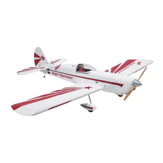
Wingspan: 82 in [2085 mm]
Wing Area: 1293 sq in [83.4 dm
Weight: 13-14.5 lb [5850-6575 g]
Wing Loading: 23-25 oz/sq ft [70-79 g/dm
Length: 72 in [1820 mm]
Radio: 4-5 channel transmitter, 6-7 servos
Engine: 1.60-2.00 cu in [26-33 cc] 2-stroke,
1.20-2.00 cu in [20-33 cc] 4-stroke,
2 cu in [32 cc] gas
Great Planes
®
Model Manufacturing Co. guarantees this kit to be free from defects in both material and workmanship at the date of
purchase. This warranty does not cover any component parts damaged by use or modification. In no case shall Great Planes' liability
exceed the original cost of the purchased kit. Further, Great Planes reserves the right to change or modify this warranty without notice.
In that Great Planes has no control over the final assembly or material used for final assembly, no liability shall be assumed nor
accepted for any damage resulting from the use by the user of the final user-assembled product. By the act of using the user-assembled
product, the user accepts all resulting liability.
If the buyer is not prepared to accept the liability associated with the use of this product, the buyer is advised to return this
kit immediately in new and unused condition to the place of purchase.
To make a warranty claim send the defective part or item to Hobby Services at the address below:
Include a letter stating your name, return shipping address, as much contact information as possible (daytime telephone number, fax
number, e-mail address), a detailed description of the problem and a photocopy of the purchase receipt. Upon receipt of the package
the problem will be evaluated as quickly as possible.
READ THROUGH THIS MANUAL BEFORE STARTING
CONSTRUCTION. IT CONTAINS IMPORTANT WARNINGS
AND INSTRUCTIONS CONCERNING THE ASSEMBLY
AND USE OF THIS MODEL.
© Copyright 2006
INSTRUCTION MANUAL
2
]
2
]
3002 N. Apollo Dr. Suite 1
Champaign IL 61822 USA
WARRANTY
Hobby Services
Champaign, Illinois
(217) 398-8970, Ext 5
airsupport@greatplanes.com
GPMZ0189 for GPMA1044 V1.0
™
Advertisement
Table of Contents

Related Manuals for GREAT PLANES Giant Super Sportster


Summary of Contents for GREAT PLANES Giant Super Sportster
-
Page 1: Instruction Manual
Further, Great Planes reserves the right to change or modify this warranty without notice. In that Great Planes has no control over the final assembly or material used for final assembly, no liability shall be assumed nor accepted for any damage resulting from the use by the user of the final user-assembled product. -
Page 2: Table Of Contents
Open the “Airplanes” Mount the Servos and Hook Up the Controls ...13 link, then select the Giant Super Sportster ARF. If there Mount the Tail Gear ...........13 is new technical information or changes to this model, a Mount the Engine and Hook Up the Throttle.....14... -
Page 3: Safety Precautions
1. Your Giant Super Sportster ARF should not be considered performance or safety of your completed model. a toy, but rather a sophisticated, working model that functions very much like a full-size airplane. -
Page 4: Fuel Tank Setup
❏ engine with a different crankshaft thread a spinner adapter kit 3' [900 mm] standard silicone fuel tubing (for glow from Great Planes or TruTurn will have to be purchased engines, GPMQ4131) ❏ R/C foam rubber (1/4" [6 mm], HCAQ1000 OR 1/2" [13 separately. -
Page 5: Important Building Notes
21st Century iron cover (COVR2702) ❏ 21st Century trim seal iron (COVR2750) IMPORTANT BUILDING NOTES Optional Supplies and Tools • The Giant Super Sportster ARF is factory-covered with Top Flite ® MonoKote ® film. The following colors were used and Here is a list of optional tools mentioned in the manual that are available in six foot [1.8m] rolls. -
Page 6: Kit Contents
If any parts are missing or are not of acceptable quality, or if you need assistance with assembly, contact Product Support. When reporting defective or missing parts, use the part names exactly as they are written in the Kit Contents list. Great Planes Product Support: 3002 N Apollo Drive, Suite 1 Champaign, IL 61822 Telephone: (217) 398-8970, ext. -
Page 7: Preparations
for the aileron servos as shown in the sketch. Also cut the PREPARATIONS covering from the 1/4" [6.5 mm] wing bolt holes, from the slots for the main landing gear wires, and from the holes for the servo wires in the top of both wings near the root ends. ❏... -
Page 8: Assemble The Wings
❏ 6. While your trim iron is out, use it to thoroughly seal the covering around the firewall, around the air passage cutout at the firewall under the fuselage, and around the formers at the front and back of the wing saddle. ❏... -
Page 9: Mount The Servos And Hook Up The Ailerons
Refer to this photo while mounting the servos and hooking up the ailerons. ❏ 2. Stick a T-pin through the middle of all the hinges. Insert four hinges into the hinge slots of each wing. ❏ 3. Without using any glue, join the ailerons to the wings and take out the T-pins. -
Page 10: Mount The Wing
Mount the Wing ❏ 1. Fit both wing halves together on the joiner tube. Then, place the wing on the fuselage, keying the dowels into the HOW TO SOLDER dowel holes in the former. ❏ A. Use denatured alcohol or other solvent to thoroughly clean the pushrod. -
Page 11: Assemble The Fuselage
ASSEMBLE THE FUSELAGE Join the Stabilizer and Fin ❏ 3. Stick a T-pin into the top of the fuselage centered over the short center mark on the firewall. Tie a loop in an approximately 60" [150 cm] piece of non-elastic string. Slip the loop in the string over the T-pin. - Page 12 ❏ 7. Peel the covering from the middle of the stabilizer. Then ❏ 5. Use a fine-point felt-tip pen to mark the outline of the wipe away the ink with a few of your paper towel squares fuselage around the top and bottom of both sides of the stab. dampened with denatured alcohol.
-
Page 13: Mount The Servos And Hook Up The Controls
cut and peel off the covering, and then use 30-minute epoxy to glue the fin into position. Use a builder’s triangle and if ALIGN THE PUSHROD HOLES necessary, pull the top of the fin over to one side or the other WITH THE PIVOT POINT. -
Page 14: Mount The Engine And Hook Up The Throttle
C-clamps so that the front of the drive washer (or the back plate of the spinner) is 7-1/4" [185 mm] from the firewall. Use a Great Planes Engine Hole Locator or a drill bit to mark the engine mounting holes into the engine mounts. -
Page 15: Gas Engine
Refer to the following two photos GAS ENGINE (FUJI BT-32) while hooking up the throttle. If mounting a gas engine other than the Fuji BT-32, use these instructions as a guide for mounting your engine in a similar manner. ❏ 1. -
Page 16: Mount The Kill Switch (Gas Engines)
Great Planes Ignition Switch Harness (GPMG2150). For the model in the manual, the Great Planes switch was used with the lever switch removed from the assembly (the servo- operated cutoff option was not used). If, in addition to the... -
Page 17: Assemble The Fuel Tank
Assemble the Fuel Tank If using a gasoline-powered engine, the fuel tank setup will have to be converted to work with gas using the hardware listed in the front of the manual. Follow these instructions for assembling your fuel tank for the type of engine you are using. -
Page 18: Install The Fuel Tank
through the fueling inlet collar. Guide the line through, and Install the Fuel Tank then insert the plastic fueling plug and press the end of the line back into the collar. Note: Do not mount the fuel tank in the aft mounting location for glow engine use. Most glow engines will not be able to draw fuel from that far away. -
Page 19: Mount The Cowl
Mount the Cowl Perform step 4A only if you have mounted a glow engine. Perform step 4B only if you have mounted a gas engine. (Remember, “Gas-only” steps are shaded.) Refer to this photo both for Steps 4A and 4B. ❏... - Page 20 the carburetor, cut out the template, and then transfer the cutout to a piece of thin cardboard or vanilla folder. Align the cardboard template with the carburetor. Next, tape the template to the fuselage. Remove the carburetor from the engine and mount the cowl. Use a fine-point felt-tip pen to draw the carb cutout onto the cowl.
-
Page 21: Final Assembly
❏ 5. Fit two mounting straps over the gear. Mark the hole locations in the straps into the wheel pant–we used our Great Planes Dead Center ™ Engine Mount Hole Locator (GPMR8130) to mark the holes. -
Page 22: Finish Radio Installation
Finish Radio Installation If using a gas engine, the model will probably require tail weight to get it to balance. If using a glow engine, the model will probably require nose weight to get it to balance. To minimize any additional nose or tail weight that may be required, mount the receiver battery in the aft location for gas engines and in one of the forward locations for glow engines. -
Page 23: Finish The Cockpit And Mount The Canopy
❏ ❏ 2. Mount the receiver and on/off switch. Connect the 4. Place the canopy on the fuselage and hold it down. servo wires and switch to the receiver and connect the Use a fine-point ballpoint pen to accurately mark the outline battery to the switch. -
Page 24: Apply The Decals
TRANSMITTER TRANSMITTER RIGHT AILERON MOVES UP CARBURETOR WIDE OPEN the Giant Super Sportster ARF flies, you would like to LEFT AILERON MOVES DOWN ❏ change the throws to suit your taste, that is fine. However, 2. Make certain that the control surfaces and the carburetor too much control throw could make the model difficult to respond in the correct direction. -
Page 25: Balance The Model (C.g.)
❏ 1. If using a Great Planes C.G. Machine, set the rulers to it in place. Over time, fuel and exhaust residue may soften 5-1/4" [133 mm]. Mount the wing to the fuselage and the adhesive and cause the weight to fall off. -
Page 26: Preflight
We use a Top Flite Precision Magnetic Prop Balancer sleeves, ties, scarfs, long hair or loose objects such as (TOPQ5700) in the workshop and keep a Great Planes pencils or screwdrivers that may fall out of shirt or jacket Fingertip Prop Balancer (GPMQ5000) in our flight box. -
Page 27: Ama Safety Code
Code that came with your AMA license. IMAA SAFETY CODE ( EXCERPTS Since the Giant Super Sportster ARF qualifies as a General “giant scale” model and is therefore eligible to fly in IMAA events, we’ve printed excerpts from the IMAA 1) I will not fly my model aircraft in sanctioned events, air Safety Code which follows. - Page 28 3.5 Proof of Flight: The completing and signing of the • There is no maximum engine displacement limit, as it is the Declaration section of the Safety Inspection form by the position of this body that an underpowered aircraft pilot (or owner) shall document as fact that each aircraft presents a greater danger than an overpowered aircraft.
-
Page 29: Check List
CHECK LIST FLYING The Giant Super Sportster ARF is a great-flying model that During the last few moments of preparation your mind may flies smoothly and predictably. It does not, however, possess be elsewhere anticipating the excitement of the first flight. -
Page 30: Flight
necessary to hold your glide path and airspeed. 3-point Flight landings are done with ease–just continue to increase up elevator, allowing the model to stall at the same time the For reassurance and to keep an eye on other traffic, it is a good main gear touches. -
Page 31: Templates
TEMPLATES Instrument Panel CUT OUT ON AIR COOLING DOTTED LINE INLET TEMPLATE DRILL 13/64" [5.2 mm] (OR 3/16" [4.8 mm] HOLES) 1.2-1.8 GLOW ENGINE MOUNTING TEMPLATE...
Need help?
Do you have a question about the Giant Super Sportster and is the answer not in the manual?
Questions and answers