Table of Contents
Advertisement
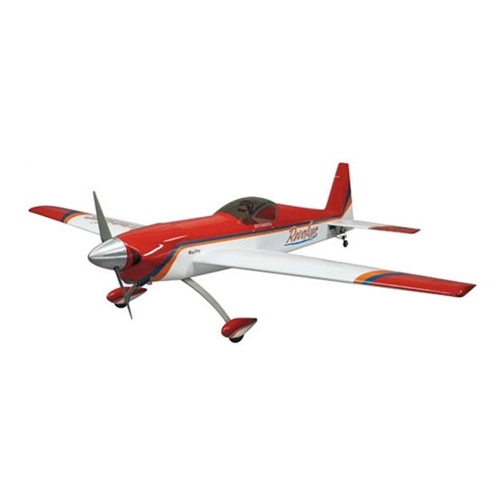
I N S T R U C T I O N M A N U A L
Wingspan: 90 in [2285 mm]
Wing Area: 1303 in
Wing Loading: 34−36 oz/ft
WARRANTY
Great Planes
®
Model Manufacturing Co. guarantees this kit to
be free from defects in both material and workmanship at the
date of purchase. This warranty does not cover any component
parts damaged by use or modification. In no case shall Great
Planes' liability exceed the original cost of the purchased kit.
Further, Great Planes reserves the right to change or modify this
warranty without notice.
In that Great Planes has no control over the final assembly or
material used for final assembly, no liability shall be assumed nor
accepted for any damage resulting from the use by the user of
the final user-assembled product. By the act of using the
user-assembled product, the user accepts all resulting liability.
If the buyer is not prepared to accept the liability associated
with the use of this product, the buyer is advised to return
READ THROUGH THIS MANUAL BEFORE STARTING CONSTRUCTION. IT CONTAINS IMPORTANT
INSTRUCTIONS AND WARNINGS CONCERNING THE ASSEMBLY AND USE OF THIS MODEL.
®
Entire Contents © 2012 Hobbico,
Inc. All rights reserved.
2
2
[84 dm
]
2
2
[104 −110 g /dm
]
Weight: 19.5 − 20.5 lb [8840 − 9300 g]
Length: 82.5 in [2095 mm]
Radio: 4 channel minimum
this kit immediately in new and unused condition to the
place of purchase.
To make a warranty claim send the defective part or item to
Hobby Services at the address below:
Include a letter stating your name, return shipping address, as
much contact information as possible (daytime telephone
number, fax number, e-mail address), a detailed description of
the problem and a photocopy of the purchase receipt. Upon
receipt of the package the problem will be evaluated as quickly
as possible.
Champaign, Illinois
email: airsupport@greatplanes.com
SPECIFICATIONS
Engine: 50 cc two stroke
Hobby Services
3002 N. Apollo Dr. Suite 1
Champaign IL 61822 USA
(217) 398-8970
gasoline engine
GPMA1425 Mnl
Advertisement
Table of Contents

Subscribe to Our Youtube Channel
Related Manuals for GREAT PLANES Revolver 50W


Summary of Contents for GREAT PLANES Revolver 50W
- Page 1 3002 N. Apollo Dr. Suite 1 Champaign IL 61822 USA In that Great Planes has no control over the final assembly or material used for final assembly, no liability shall be assumed nor Include a letter stating your name, return shipping address, as...
-
Page 2: Table Of Contents
For the latest technical updates or manual a full-size airplane. Because of its performance capabilities, corrections to the Revolver, visit the Great Planes web site at the Revolver, if not assembled and operated correctly, could www.greatplanes.com. Open the “Airplanes” link, then select possibly cause injury to yourself or spectators and damage the Revolver 50cc ARF. -
Page 3: Decisions You Must Make
❍ 2- Heavy Duty Dual Servo Lead (FUTM4135 for Futaba). range is used, the modeler is responsible for taking steps to reinforce the high stress points and/or substituting hardware If you choose to use a dual servo lead or “Y” harnesses to more suitable for the increased stress. -
Page 4: Kit Inspection
fi rst position the part on the assembly without using any glue, then slightly modify or custom To locate a hobby dealer, visit the Great Planes web site at fi t the part as necessary for the best fi t. -
Page 5: Kit Contents
KIT CONTENTS Kit Contents 1. Right Wing w/ Aileron 7. Landing Gear 13. Rudder 2. Left Wing w/ Aileron 8. Fuel Tank 14. Tail Wheel Assembly 3. Wing Tube 9. Right Stab & Elevator 15. Fuselage 4. Spinner 10. Left Stab & Elevator 16. - Page 6 ❏ ❏ 2. Drill a 1/16" [1.6mm] hole in the hatch covers through the mounting blocks approximately 3/8" [9.5mm] deep. Thread a #2 x 3/8" [9.5mm] fl at head wood screw into each hole and back it out. Apply a drop of thin CA glue to each hole to ❏...
- Page 7 CORRECT INCORRECT HOW TO SOLDER 1. Use denatured alcohol or other solvent to thoroughly clean the pushrod. Roughen the end of the pushrod with coarse sandpaper where it is to be soldered. Hinge Line Hinge Line 2. Apply a few drops of soldering fl ux to the end of the pushrod, and then use a soldering iron or a torch to heat it.
-
Page 8: Build The Fuselage
has cooled slide the clevis retainer over the solder clevis. Center you servo and then install the pushrod into the control horn and the servo arm. Adjust the clevis as needed and then tighten the 4-40 nut against the clevis. Be sure to apply a drop of thread locker to the threaded wire and nut. -
Page 9: Install The Elevator Servos
Install the Elevator Servos Note: Steps 1 and 2 describe the installation of the servo lead for the elevator servos. The installation described uses one extension and a “Y” connector. Some might prefer a separate line for each servo. Either method is acceptable. ❏... -
Page 10: Install The Rudder
❏ 7. Locate two 4-40 x 5-3/4" [146mm] threaded pushrod wires, 4-40 nuts, 4-40 threaded clevises, 4-40 solder clevises and silicone clevis keepers. Use the same procedure used for making the aileron pushrods and make two pushrod wires for the elevators. Install the Rudder ❏... -
Page 11: Install The Landing Gear
❏ ❏ 2. Cut the axles to a length of 1-13/16" [46mm]. Secure ❏ 4. The rudder has a plywood control horn mounting plate the axles to the landing gear legs using the 5/16"-24 nylon built-in. Place a control horn onto the plate in line with the hole lock nuts. - Page 12 ❏ 7. Drill a 3/32" [2.4mm] hole though each of the marks you made. Install and then remove a #4 x 5/8" [16mm] screw into the holes you drilled. Apply a couple of drops of thin CA into the holes to harden the threads. Set the fuselage aside until the glue hardens.
-
Page 13: Install The Rudder Servo & Pull-Pull Wires
❏ of the tail wheel assembly, inserting and twisting the wires 10. Re-assemble the into the control horn and steering arm in the holes shown. tail wheel as shown. Be sure that you apply a drop of thread locker onto the Install the Rudder Servo screws. -
Page 14: Install The Engine, Fuel Tank & Remaining Servos
❏ ❏ 4. Slide a small swage over one end of the cables and then guide the end of the cable through the hole in the end of the 4-40 threaded brass connector and back through the swage. ❏ 9. Install the clevises into the holes of the rudder control horns as shown. - Page 15 have to make spacers or use a proper length stand-off to Many modelers have their own opinions for connectors accommodate your engine. For reference, the distance from and throttle linkage. We have provided materials for a the front of the fi rewall to the front of the drive washer is 6-3/4" secure and safe throttle linkage.
- Page 16 ❏ 6. Locate three brass tubes and fi ve fuel barbs. Solder the barbs to one end of each of the three tubes. ❏ 7. Insert each of the three tubes through the metal plates and the rubber stopper. Note: One of the holes in the stopper ❏...
- Page 17 ❏ 14. Locate the 36" [914mm] inner pushrod tube and cut a 13" [330mm] piece from it. Screw a 2-56 x 1" [25mm] threaded wire ¼" [6mm] into the inner pushrod. Screw a nylon ball link onto the threaded wire. Slide the pushrod tube into the tube you installed in the fi...
- Page 18 choke servo you should know that the location of the servo will make it a little more diffi cult to tighten the wing attachment bolt. If you will be using a manual choke skip ahead to step 24. ❏ 16. Locate the plywood choke servo tray parts and the ❏...
-
Page 19: Install The Radio System
❏ 25. Install fuel lines onto each of the lines coming out of ❏ 22. Screw a 2-56 x 1" [25mm] threaded wire ¼" [6mm] into the fuel tank. Once the lines have been installed feed the lines the remaining inner pushrod. Screw the nylon ball link you cut through opening in the front of the fuselage. -
Page 20: Complete The Engine Installation, Mount The Cowl, Prop & Spinner
❏ 2. Install a 6" [152mm] extension on the choke servo Complete the Engine Installation, and a 12" [305mm] extension on the throttle servo. Secure Mount the Cowl, Prop & Spinner the connections with heat shrink tubing, tape or some other method to secure the connectors. - Page 21 ❏ 4. In order to fi t the cowl over the engine and muffl er you will need to shorten the exhaust pipes of the muffl er. If you are installing the DLE 55 and the recommended J-Tec muffl er you will need to shorten the pipes by approximately 2-1/4"...
- Page 22 ❏ ❏ 9. Put the cowl back onto the fuselage. You will need to 11. Rotate the prop shaft until the engine is on compression make some clearance in the cowl for the spark plug lead. (the piston is at the top of the cylinder). Slide your prop onto Make fi...
- Page 23 ❏ 14. Mount the back plate, prop and prop washer with the engine bolts to be sure everything aligns. Make adjustments as needed. ❏ 13. Slide the spinner back plate onto the prop shaft followed by the newly drilled prop. Set the prop so it is positioned properly.
-
Page 24: Apply The Decals
❏ 15. Install the canopy onto the top of the fuselage, aligning the pins in the front of the canopy with the holes behind the cowl. Secure the canopy with four 4-40 x1" [25mm] screws, #4 fl at washers and #4 lock washers. Apply the Decals Use the photos on the box to determine where to place your decals. -
Page 25: Set The Control Throws
4-CHANNEL RADIO SETUP (STANDARD MODE 2) RIGHT AILERON RUDDER MOVES UP MOVES LEFT AILERON RIGHT MOVES DOWN ❏ 2. Hold a ruler vertically on your workbench against the widest part (front to back) of the trailing edge of the elevator. Note the measurement on the ruler. -
Page 26: Balance The Model (C.g.)
Once you ❏ 1. If using a Great Planes C.G. Machine, set the rulers to have determined the amount of weight required, it can be 7-7/8" [200mm]. If not using a C.G. Machine, use a fi ne-point permanently attached. -
Page 27: Preflight
We use a Top Flite Precision Magnetic Prop Balancer (TOPQ5700) in the workshop and keep a Great Planes Fingertip Prop Balancer (GPMQ5000) in our fl ight box. -
Page 28: Ama Safety Code
AMA SAFETY CODE CHECK LIST Read and abide by the following excerpts from the Academy During the last few moments of preparation your mind may of Model Aeronautics Safety Code. For the complete Safety be elsewhere anticipating the excitement of the fi rst fl ight. Code refer to Model Aviation magazine, the AMA web site or Because of this, you may be more likely to overlook certain the Code that came with your AMA license. -
Page 29: Flying
❏ will roll straight down the runway. If you need to calm your 16. Balance your propeller (and spare propellers). nerves before the maiden fl ight, shut the engine down and ❏ 17. Tighten the propeller nut and spinner. bring the model back into the pits. Top off the fuel, then check all fasteners and control linkages for peace of mind. - Page 30 smoothly advance the throttle (always ready on the right rudder attempting a maneuver and suddenly fi nding that you’ve run to counteract torque) and climb out to make another attempt. out of time, altitude or airspeed. Every maneuver should be When you’re ready to make your landing fl...
-
Page 31: Dle55 Mounting Pattern
80 mm DLE 55 Mounting Pattern 67 mm This model belongs to: Name Address City, State, Zip Phone Number AMA Number... - Page 32 GPMA1425 Mnl...
Need help?
Do you have a question about the Revolver 50W and is the answer not in the manual?
Questions and answers