Table of Contents
Advertisement
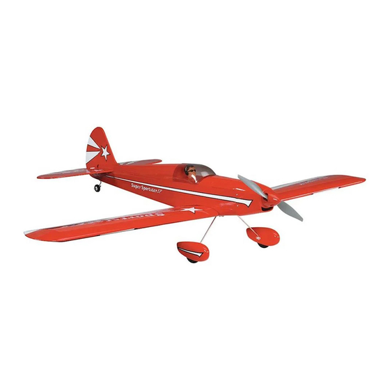
Wingspan: 48 in [1220mm]
Wing Area: 383 sq in [24.7 dm
Weight: 3-1/4 lb [1470 g]
Wing Loading: 19.5 oz/sq ft [60 g/dm
Length: 39 in [990mm]
Radio: 4-channel with three mini servos
Motor: 550 size
Electronic Speed Control: 30 amp
Great Planes
®
Model Manufacturing Co. guarantees this kit to be free from defects in both material and workmanship at the date of
purchase. This warranty does not cover any component parts damaged by use or modification. In no case shall Great Planes' liability
exceed the original cost of the purchased kit. Further, Great Planes reserves the right to change or modify this warranty without notice.
In that Great Planes has no control over the final assembly or material used for final assembly, no liability shall be assumed nor
accepted for any damage resulting from the use by the user of the final user-assembled product. By the act of using the user-assembled
product, the user accepts all resulting liability.
If the buyer is not prepared to accept the liability associated with the use of this product, the buyer is advised to return this
kit immediately in new and unused condition to the place of purchase.
To make a warranty claim send the defective part or item to Hobby Services at the address below:
Include a letter stating your name, return shipping address, as much contact information as possible (daytime telephone number, fax
number, e-mail address), a detailed description of the problem and a photocopy of the purchase receipt. Upon receipt of the package
the problem will be evaluated as quickly as possible.
READ THROUGH THIS MANUAL BEFORE STARTING
CONSTRUCTION. IT CONTAINS IMPORTANT WARNINGS
AND INSTRUCTIONS CONCERNING THE ASSEMBLY
AND USE OF THIS MODEL.
© Copyright 2004
INSTRUCTION MANUAL
2
]
2
]
3002 N. Apollo Dr. Suite 1
Champaign IL 61822 USA
WARRANTY
Hobby Services
Champaign, Illinois
(217) 398-8970, Ext 5
airsupport@greatplanes.com
GPMZ0201 for GPMA1160 V1.0
Advertisement
Table of Contents

Related Manuals for GREAT PLANES Super Sportster EP ARF


Summary of Contents for GREAT PLANES Super Sportster EP ARF
-
Page 1: Instruction Manual
Further, Great Planes reserves the right to change or modify this warranty without notice. In that Great Planes has no control over the final assembly or material used for final assembly, no liability shall be assumed nor accepted for any damage resulting from the use by the user of the final user-assembled product. -
Page 2: Table Of Contents
ADDITIONAL ITEMS REQUIRED ........3 For the latest technical updates or manual corrections to the Hardware and Accessories..........3 Super Sportster EP ARF visit the Great Planes web site at Adhesives and Building Supplies.........3 www.greatplanes.com. Open the “Airplanes” link, then Optional Supplies and Tools ........4 select the Super Sportster EP ARF. -
Page 3: Battery Charger Options
OPTIONS” section, the following is the list of hardware and quality and flyability of your finished model depends on accessories required to finish the Super Sportster EP ARF. how you build it; therefore, we cannot in any way Order numbers are provided in parentheses. -
Page 4: Optional Supplies And Tools
• When you see the term test fit in the instructions, it means #11 blades (5-pack, HCAR0211) that you should first position the part on the assembly Medium T-pins (100, HCAR5150) without using any glue, then slightly modify or custom fit Builder’s Triangle Set (HCAR0480) the part as necessary for the best fit. -
Page 5: Kit Inspection
If any parts are missing or are not of acceptable quality, or if you need assistance with assembly, contact Product Support. When reporting defective or missing parts, use the part names exactly as they are written in the Kit Contents list. Great Planes Product Support: 3002 N Apollo Drive, Suite 1 Champaign, IL 61822 Telephone: (217) 398-8970, ext. -
Page 6: Ordering Replacement Parts
To locate a hobby dealer, visit the Great Planes web site at www.greatplanes.com. Choose “Where to Buy” at the bottom of the menu on the left side of the page. Follow the instructions provided on the page to locate a U.S., Canadian or International dealer. -
Page 7: Preparations
PREPARATIONS 1. If you have not done so already, remove the major parts of the kit from the box (wing, fuselage, tail parts, etc.) and inspect them for damage. If any parts are damaged or missing, contact Product Support at the address or telephone number on the front cover. -
Page 8: Join The Wing Halves
good fit. Note: The dihedral angle is factory-set and determined by the angle of the joiner and the joining ribs on the ends of the wing halves. However, you may confirm the dihedral by placing one wing panel flat on the workbench and measuring the distance between the bottom of the rib on the end of the other panel and the bench. -
Page 9: Assemble The Fuselage
Mount the Stabilizer and Fin 5. Using a sharp hobby knife, cut the covering and balsa sheeting from the inside of the aileron servo tray area. Trim only the covering from the outer aileron servo tray area. 1. Using a sharp hobby knife, remove the covering from 6. - Page 10 6. Use a fine-point felt-tip pen to mark the outline of the fuselage onto the bottom and top of the stab. 7. Remove the stab from the fuselage. Use a sharp #11 hobby knife or the Expert Tip that follows to cut the covering from the stab just inside the lines you marked.
- Page 11 9. Cut the covering from the rudder slot in the top of the fuselage. 10. Apply a light coat of 30-minute epoxy in the stabilizer slot and the top and bottom of the stabilizer. Slide the stabilizer into position. Make sure the stabilizer is centered. Use the string method to re-align the stab with the fuselage.
-
Page 12: Radio Installation
20. Once satisfied with the fit of the tail gear wire in the 16. Position the rudder at the trailing edge and mark the rudder, apply epoxy in the tail gear wire hole in the leading location where the elevator joiner wire passes through the edge of the rudder. - Page 13 where the pushrods press against the covering. Using a sharp hobby knife, cut a small slot in the covering to allow the pushrod to exit the fuselage. 4. Connect the pushrod wire to the control horn with a 1.7mm wheel collar and 2.5mm set screw. 5.
- Page 14 2. Cut a piece of soft hook-and-loop material and use CA 5. Install the two pushrod connectors on the rudder and to glue it to the bottom of your receiver. Cut an opposite elevator servo horns by first inserting the connector through piece of the hook-and-loop material and glue it in the the horn, then install a 2mm washer and an 2mm nut on the fuselage behind the servo tray.
-
Page 15: Mount The Cowl And Prop
9. Install a two-arm servo arm with holes 7/16" [11mm] MOUNT THE COWL AND PROP from the center of the arm. 1. Slide the cowl over the front of the fuselage. 10. Thread the two nylon torque rod horns onto the aileron torque rods. -
Page 16: Mount The Landing Gear
5. Attach the spinner cone to the spinner backplate with MOUNT THE LANDING GEAR two 3x10mm self-tapping screws. 1. Trim the covering from the main landing gear slot in the bottom of the fuselage. 6. Tape the cowl to the fuselage so that the aft edge is 2. -
Page 17: Finish The Model
5. Use sandpaper to roughen the inside of the wheel pant in the area around the mounting slot. Clean the area with denatured alcohol. Trial fit the plywood wheel pant 8. Install a 3x4mm machine screw in two 3mm wheel mounting plate inside the wheel pant. -
Page 18: Install The Battery Hatch
Mount the Battery Hatch 1. Use a needle-nose pliers to open the two eye hooks. 5. To make the battery strap, overlap the two pieces of hook-and-loop material as shown. 2. Using a T-pin, make two small pilot holes in the base of the battery hatch cover 3/8"... -
Page 19: Apply The Decals
GET THE MODEL READY TO FLY Check the Control Directions Warning: Once the motor battery is connected to the electronic speed control, stay clear of the propeller. 1. Switch on the transmitter and connect the motor battery to the electronic speed control. Move the throttle stick down to the off position. -
Page 20: Set The Control Throws
1. Use a felt-tip pen or 1/8" [3mm]-wide tape to accurately mark the C.G. on the top of the wing on both sides of the Use a Great Planes AccuThrow (or a ruler) to accurately fuselage. The C.G. is located 2-3/4" [70mm] back from the measure and set the control throw of each control surface as leading edge of the wing. -
Page 21: Balance The Model Laterally
We use a Top Flite Precision Magnetic Prop Balancer ™ [TOPQ5700] in the workshop and keep a Great Planes Fingertip Prop Balancer [GPMQ5000] in our flight box. PREFLIGHT PROPER CARE OF YOUR MOTOR Identify Your Model 1. -
Page 22: Performance Tips
3. Using multiple battery packs to run the motor for MOTOR SAFETY PRECAUTIONS successive flights may cause the motor to become excessively hot. We recommend at least a 10-minute motor cool-down period between flights. Failure to follow these safety precautions may result in severe injury to yourself and others. -
Page 23: Check List
7. Reinforce holes for wood screws with thin CA where Radio Control appropriate (servo mounting screws, cowl mounting screws, etc.). 1) I will have completed a successful radio equipment ground 8. Confirm that all controls operate in the correct direction check before the first flight of a new or repaired model. -
Page 24: Takeoff
maintain airspeed by keeping the nose down as you turn onto Takeoff the crosswind leg. Make your final turn toward the runway (into the wind) keeping the nose down to maintain airspeed Before you get ready to takeoff, see how the model handles and control.