Table of Contents
Advertisement
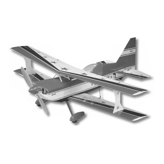
Wingspan: 33.5" [850mm]
Fuselage Length: 37" [935mm]
Wing Area: 383 sq in [24.7dm2]
Weight Range: 27.5-31oz [780-880g]
Wing Loading: 10.3-11.6 oz/sq ft [32-36 g/dm2]
Motor: 35-30-950kV RimFire Outrunner Motor
Radio: 4-Channel Minimum with Micro Receiver and Four Micro Servos
Great Planes
®
Model Manufacturing Co. guarantees this kit to
be free from defects in both material and workmanship at the date
of purchase. This warranty does not cover any component parts
damaged by use or modifi cation. In no case shall Great Planes'
liability exceed the original cost of the purchased kit. Further,
Great Planes reserves the right to change or modify this warranty
without notice.
In that Great Planes has no control over the fi nal assembly or
material used for fi nal assembly, no liability shall be assumed nor
accepted for any damage resulting from the use by the user of
the fi nal user-assembled product. By the act of using the user-
assembled product, the user accepts all resulting liability.
If the buyer is not prepared to accept the liability associated
with the use of this product, the buyer is advised to return
READ THROUGH THIS MANUAL BEFORE STARTING CONSTRUCTION. IT CONTAINS IMPORTANT
INSTRUCTIONS AND WARNINGS CONCERNING THE ASSEMBLY AND USE OF THIS MODEL.
Entire Contents © Copyright 2007
INSTRUCTION MANUAL
WARRANTY
this kit immediately in new and unused condition to the place
of purchase.
To make a warranty claim send the defective part or item to Hobby
Services at the address below:
Include a letter stating your name, return shipping address, as
much contact information as possible (daytime telephone number,
fax number, e-mail address), a detailed description of the problem
and a photocopy of the purchase receipt. Upon receipt of the
package, the problem will be evaluated as quickly as possible.
Hobby Services
3002 N. Apollo Dr., Suite 1
Champaign, IL 61822 USA
Champaign, Illinois
(217) 398-8970, Ext 5
airsupport@greatplanes.com
GPMZ1546 for GPMA1546 V1.0
Advertisement
Table of Contents

Related Manuals for GREAT PLANES Ultimate Biplane EP ARF


Summary of Contents for GREAT PLANES Ultimate Biplane EP ARF
-
Page 1: Instruction Manual
Hobby Services 3002 N. Apollo Dr., Suite 1 In that Great Planes has no control over the fi nal assembly or Champaign, IL 61822 USA material used for fi nal assembly, no liability shall be assumed nor accepted for any damage resulting from the use by the user of Include a letter stating your name, return shipping address, as the fi... -
Page 2: Table Of Contents
TABLE OF CONTENTS INTRODUCTION The Ultimate Biplane EP ARF is the third release in a line of INTRODUCTION ............... 2 electric built-up, all-out performance 3D planes. The Ultimate SAFETY PRECAUTIONS ..........3 is a fantastic fl yer and can perform virtually any aerobatic LITHIUM BATTERY HANDLING AND USAGE .... -
Page 3: Safety Precautions
Remember: Take your time and follow the instructions to end up with a well-built model that is straight and true. 1. Your Ultimate Biplane EP ARF should not be considered a toy, but rather a sophisticated, working model that functions very much like a full-size airplane. -
Page 4: Additional Items Required
Futaba R114F FM Micro Receiver (Low Band – FUTL0442, This is the list of adhesive and building supplies required High Band – FUTL0443) to fi nish the Ultimate Biplane EP ARF. Order numbers are ❏ Futaba FM Single Conversion Short Crystal provided in parentheses. -
Page 5: Important Building Notes
• Whenever the term glue is written you should rely upon To locate a hobby dealer, visit the Great Planes web site your experience to decide what type of glue to use. When at www.greatplanes.com. -
Page 6: Kit Contents
If any parts are missing or are not of acceptable quality, or if you need assistance with assembly, contact Product Support. When reporting defective or missing parts, use the part names exactly as they are written in the Kit Contents list. Great Planes Product Support 3002 N. Apollo Drive, Suite 1 Champaign, IL 61822 Telephone: (217) 398-8970, ext. -
Page 7: Before You Begin
BEFORE YOU BEGIN Before you begin assembly, closely inspect all of the covered components. Carefully remove the control surfaces that are taped in place. Use a covering iron with a covering iron sock on low/medium heat to tighten the covering in any areas that are loose, disconnected, or wrinkled. -
Page 8: Install The Aileron Servos And Pushrods
Install the Aileron Servos & Pushrods ❏ 4. Feed the servo leads through the servo bays and out the cutouts in the wing root ribs. Position the servos in the servo bays with the splines toward the LE. Glue the aileron ❏... -
Page 9: Attach The Wings
carbon fi ber pushrod. Loosely thread a 2x4mm self-tapping screw into each clevis. The screw head should be in the recessed end of the hole in the clevis. Hook the clevis to the outer holes in the servo arms. ❏ ❏ 9. - Page 10 ❏ 4. Before you begin this step, prepare a weighted object to hold the fuselage and wings in place while the epoxy cures. We used a sock fi lled with sand as shown in the picture. Coat the root ribs of the bottom wing panels with 30-minute epoxy (Do not put epoxy on the spars until instructed to do so in the next step).
-
Page 11: Build The Fuselage
Be sure you are drilling through the center of the elevators, BUILD THE FUSELAGE perpendicular to the LE. Trim away approximately 1/16" [1.6mm] of the LE between the holes you made and the inside edge of the elevators. Assemble the Tail Section ❏... - Page 12 ❏ 6. Trim the covering from the stab just inside the lines you drew. Wipe away the lines with denatured alcohol. ❏ 8. As you did with the ailerons, join the elevator halves to the stabilizer using the elevator joiner rod and CA hinges. Before gluing the hinges, be sure that the elevator halves move freely HOW TO CUT COVERING FROM BALSA up and down.
-
Page 13: Install The Tail Servos And Pushrods
Install the Tail Servos & Pushrods ❏ 3. With the elevator servo centered, attach a double-sided servo arm vertically. Determine which way the arm fi ts best. Cut the unused side from the servo arm, leaving the bottom side as shown. As you did with the ailerons, loosely thread a 2x4mm self-tapping screw into an adjustable clevis and slide it on a 2x135mm carbon pushrod. -
Page 14: Install The Top Wing
❏ 5. Install the 2x135mm rudder pushrod in the same manner. Install the Top Wing ❏ 3. Trim the covering from interplane strut slots in the bottom wing as well as the cabane slots in the fuselage. ❏ 1. Trim the covering that overlaps onto the root ribs of the top wing panels. - Page 15 ❏ 5. Trim the covering from the interplane strut slots on the underside of the top wing. Repeat step #4 for the top interplane strut slots. Read all of steps 6-9. Test fi t all parts together (without glue) before proceeding. ❏...
-
Page 16: Finish The Model
❏ ❏ 10. Cut four sides from servo arms left over in the hardware bag. 12. Center the ailerons and join the top and bottom together Cut them off close to the center so they are as long as possible. using adjustable clevises and the remainder of the 2x215mm aileron pushrods. -
Page 17: Install The Out-Runner Motor
❏ 4. Use a hobby knife to cut the covering over the slot in the bottom of the tail skid. Glue the tail skid washer into the slot as shown. The washer will help to prevent wear to the skid when fl... -
Page 18: Install The Electronics
❏ 2. Attach the prop adapter to the front of the motor case using the screws included with the motor. Harden the motor ❏ 2. Connect the ESC to the motor leads and feed the receiver mounting holes in the plywood motor adapter with thin CA lead through the front of the fuselage. -
Page 19: Install The Cowl
❏ 5. Make a battery strap out of the supplied hook and loop material 8" [200mm] long by overlapping two pieces and cutting it to length. Feed it through the battery tray in the location shown. The battery strap can be glued to the battery tray with medium CA to keep it in place. -
Page 20: Final Assembly
❏ 5. Slide the cowl over the cowl ring and onto the fuselage. Confi rm that the spinner backplate properly fi ts your motor shaft. If not, ream or drill it to the correct diameter. Temporarily install the spinner backplate onto the prop shaft. Adjust the position of the cowl on the fuselage so that the colors line up with the stripes on the fuselage. -
Page 21: Apply The Decals
❏ 4. Before attaching the canopy, apply the instrument panel decal to the cockpit. The canopy can be taped in position as shown. Apply the Decals 1. Use scissors or a sharp hobby knife to cut the decals from the sheet. ❏... -
Page 22: Get The Model Ready To Fly
Adjust if necessary. AILERONS: 1/2" [13mm] up 1/2" [13mm] down IMPORTANT: The Ultimate Biplane EP ARF has been extensively fl own and tested to arrive at the throws at which it fl ies best. Flying your model at these throws will provide you with the greatest chance for successful fi... -
Page 23: Balance The Model (C.g.)
If possible, relocate the battery pack and receiver to minimize or eliminate any additional ballast required. The Ultimate Biplane EP ARF is designed so that additional weight should not need to be added for balancing purposes. Changing to a lighter (1250mAh) or heavier (2100mAh) battery pack will shift the balance point from the forward At this stage the model should be in ready-to-fl... -
Page 24: Preflight
We use a Top Flite Precision Magnetic Prop Balancer ™ shows, or model fl ying demonstrations until it has been (TOPQ5700) in the workshop and keep a Great Planes proven to be airworthy by having been previously, successfully fl ight tested. -
Page 25: Check List
4) I will operate my model using only radio control frequencies currently allowed by the Federal Communications Commission. The Ultimate Biplane EP ARF is a great-fl ying model that 5) I will not knowingly operate my model within three miles fl... -
Page 26: Takeoff
While full throttle is usually desirable for takeoff, most models fl y more smoothly at reduced speeds. Take it easy with the Ultimate Biplane EP ARF for the fi rst few fl ights, gradually getting acquainted with it as you gain confi... -
Page 27: 3D Flying
INVERTED FLAT SPINS 3D FLYING This is the same as the up-right fl at spin except most planes like to spin in the opposite direction, for example: right rudder Because of the power-to-weight ratio on 3D planes, straight and down elevator. and level fl... - Page 28 TORQUE ROLL ROLLING HARRIER This is the same as the vertical hover but without the use of right aileron to keep the model from rolling. If needed, you can use a little left aileron to speed the roll up. As the model rotates around, the controls will appear to be reversed to you but only the orientation of the model has changed.
Need help?
Do you have a question about the Ultimate Biplane EP ARF and is the answer not in the manual?
Questions and answers