Table of Contents
Advertisement
Quick Links
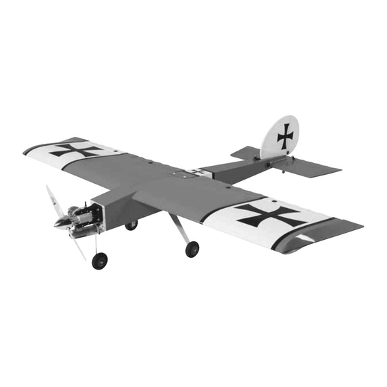
Wingspan: 80.5 in [2045mm]
Wing Area: 1518 sq in [97.9 dm
Weight: 13-15 lb [5900–6800g]
Wing Loading: 20–23 oz/sq ft [61–70 g/dm
Length: 54.5 in [1385mm]
Radio: 4 or 5-channel, 7 to 8 servos
Engine: 1.2–1.6 cu in [19.5–26.0cc] two-stroke,
1.2–1.8 cu in [19.5–29.5cc] four-stroke,
1.5–2.1 cu in [25–35cc] gas
Great Planes
®
Model Manufacturing Co. guarantees this kit to be free from defects in both material and workmanship at the date of purchase. This
warranty does not cover any component parts damaged by use or modification. In no case shall Great Planes' liability exceed the original cost of the
purchased kit. Further, Great Planes reserves the right to change or modify this warranty without notice.
In that Great Planes has no control over the final assembly or material used for final assembly, no liability shall be assumed nor accepted for any
damage resulting from the use by the user of the final user-assembled product. By the act of using the user-assembled product, the user accepts all
resulting liability.
If the buyer is not prepared to accept the liability associated with the use of this product, the buyer is advised to return this kit immediately in new and
unused condition to the place of purchase.
To make a warranty claim send the defective part or item to Hobby Services at the address below:
Include a letter stating your name, return shipping address, as much contact information as possible (daytime telephone number, fax number, e-mail
address), a detailed description of the problem and a photocopy of the purchase receipt. Upon receipt of the package the problem will be evaluated as
quickly as possible.
READ THROUGH THIS MANUAL BEFORE STARTING
CONSTRUCTION.
INSTRUCTIONS AND WARNINGS CONCERNING
THE ASSEMBLY AND USE OF THIS MODEL.
Entire Contents © Copyright 2005
INSTRUCTION MANUAL
]
2
2
]
3002 N. Apollo Dr., Suite 1
IT
CONTAINS
WARRANTY
Hobby Services
Champaign, IL 61822
USA
IMPORTANT
™
Champaign, IL
(217) 398-8970, Ext. 5
airsupport@greatplanes.com
GPMZ0197 for GPMA1224 V1.0
Advertisement
Table of Contents

Related Manuals for GREAT PLANES Giant Big Stir ARF


Summary of Contents for GREAT PLANES Giant Big Stir ARF
-
Page 1: Instruction Manual
Further, Great Planes reserves the right to change or modify this warranty without notice. In that Great Planes has no control over the final assembly or material used for final assembly, no liability shall be assumed nor accepted for any damage resulting from the use by the user of the final user-assembled product. -
Page 2: Table Of Contents
ARF. Due to the popularity of the “Stik” series of models, it SAFETY PRECAUTIONS ..........3 was only a matter of time before Great Planes released a DECISIONS YOU MUST MAKE ........3 giant version. And this Stik, like all of its predecessors, is Engine Recommendations...........3... -
Page 3: Imaa
8. While this kit has been flight tested to exceed normal use, if the plane will be used for extremely high stress flying, such as The Great Planes Giant Big Stik ARF is an excellent sport- racing, or if an engine larger than one in the recommended scale model and is eligible to fly in IMAA events. -
Page 4: Fuel Tank Setup
Slightly different hardware may be required if using a different spark-ignition engine. All of the components required are available at any hardware or home- The model on the kit box cover is shown with a Great Planes improvement store. 2-3/4" [70mm] aluminum spinner (GPMQ4555) (not included). -
Page 5: Additional Items Required
In addition to common household tools and hobby tools, this length. For example, #6 x 3/4" [19mm]. is the “short list” of the most important items required to build the Giant Big Stik ARF. Great Planes Pro ™ CA and Epoxy glue are recommended. -
Page 6: Champaign, Il
24" = 609.6 mm 1/2" 12.7 mm 30" = 762.0 mm Replacement parts for the Great Planes Giant Big Stik ARF 5/8" 15.9 mm 36" = 914.4 mm are available using the order numbers in the Replacement Parts List that follows. The fastest, most economical service can be provided by your hobby dealer or mail-order company. -
Page 7: Kit Inspection
If any parts are missing or are not of acceptable quality, or if you need assistance with assembly, contact Great Planes Product Support. When reporting defective or missing parts, use the part names exactly as they are written in the Kit Contents list on this page. -
Page 8: Preparations
PREPARATIONS ASSEMBLE THE WINGS Mount the Servos ❏ 1. Use a straightedge and a hobby knife to cut the covering 1/8" [3mm] inside the openings in the bottom of both wings for the flap and aileron servos. During construction there will be several occasions where epoxy cleanup will be necessary. -
Page 9: Hinge The Flaps & Ailerons
❏ ❏ 5. Use the strings in the wings to pull the servo wires out 2. Stick a T-pin through the middle of all the hinges. Insert while placing the servos into the openings. With the servos six hinges into the hinge slots of both wings. in position, drill 1/16"... - Page 10 If you’re not building your Giant Big Stik ARF with flaps hook up the servos this way. ❏ 3. Use a fine-point felt-tip pen to mark the pushrod where it should be cut for soldering onto the clevis. ❏ 4. Cut the pushrod at the mark. Take the clevis off the horn, then refer to the “Expert Tip”...
-
Page 11: Finish The Wings
❏ 5. Reconnect the pushrod to the servo horn, then mark Finish the Wings and drill 1/8" [3.2mm] holes through the aileron for the control horn mounting screws. Mount the horn to the aileron with four 4-40 x 3/4" [19mm] screws and the mounting plate on the top. -
Page 12: Assemble The Fuselage
ASSEMBLE THE FUSELAGE Mount the Stab There are a few preparation and alignment procedures that must be done before the stabilizer can be glued into the fuselage... ❏ 4. Stick another T-pin into the bottom of the fuselage centered over the firewall. Tie a loop in an approximately 70"... -
Page 13: Mount The Fin
❏ ❏ 8. Stand approximately ten feet behind the model and see 10. Peel the covering from the stab. Remove any ink with one if the stab aligns horizontally with the wing. If they align, go to of your paper towel squares dampened with denatured alcohol. the next step. - Page 14 stabilizer. If necessary, use a long strip of masking tape to pull the top of the fin over to one side or the other of the stab. If flying your Giant Big Stik ARF with a Fuji BT-32, the nose-gear option may not be used due to the distance that the engine would have to be extended from the firewall.
-
Page 15: Mount The Landing Gear
Follow these steps if building your Giant Big Stik ARF Mount the Landing Gear with nose gear. Otherwise, skip to step 1 on page 16. ❏ 5. Tricycle: Use a metal file, wire cutters or a rotary tool with a cut-off wheel to grind one edge off of two 6-32 blind nuts. ❏... -
Page 16: Mount The Engine
Use a large T-pin or a wire sharpened on the end to transfer you position the engine on the mount.) Use a Great Planes the bolt hole marks on the template into the firewall. - Page 17 ❏ 6. Glue together the two 1/4" [6.4mm] plywood Fuji ❏ 1. Cut the Fuji BT-32 Engine Mount Template from the engine mount plates. Install four 10-32 blind nuts (not back of the manual 1/16" [1.6mm] outside the dashed lines. included) in the back of the plate where shown.
-
Page 18: Install The Fuel Tank
the throttle pushrod guide tube–this may require temporary Otherwise, assemble the stopper assembly to suit your removal of the engine. Drill the hole at an angle so the guide requirements for glow–most applications will require only a tube will cross to the other side of the fuselage and so the two-line system–one line for the fuel pickup and pushrod will align with the carburetor arm on the engine. -
Page 19: Hook Up The Throttle & Nose Gear Steering
❏ 3. Determine how far forward or aft you will be mounting the fuel tank in the fuel tank compartment. The tank may be ❏ positioned to accommodate a battery pack for the electronic 1. If you’ve installed a Fuji engine, the throttle pushrod is ignition system should you be using one on a spark-ignition already connected to the engine. -
Page 20: Hook Up The Elevator & Rudder Servos
forget to temporarily remove the servo mounting screws, GET THE MODEL READY TO FLY harden the holes with thin CA, allow to harden, then reinstall the screws. ❏ 6. If you’ve installed the nose gear, temporarily remove Mount the Receiver & Battery the nose gear wire and file a flat spot for the screw in the steering arm. -
Page 21: Center The Servos
5. Mount the receiver on/off switch in a location that is easily accessible and will not get coated by engine exhaust. A Great Planes Switch & Charge Jack Mounting Set With the radio system connected and operating, turn on the (GPMM1000) was used on this model and is a great way to transmitter and receiver. -
Page 22: Set The Control Throws
AILERONS: 1-1/4" [32mm] up 1" [25mm] up will be using a Great Planes C.G. Machine to balance the 1-1/4" [32mm] down 1" [25mm] down model, set the rulers to 5-7/8" [150mm], then mount the wing to the fuselage and proceed to the next step. If you will FLAPS: 1-5/8"... -
Page 23: Balance The Model Laterally
(GPMQ4645 for the 1 oz. [28g] weight, or GPMQ4646 for the 2 oz. [57g] weight). If spinner weight cannot be used or is not enough, use Great Planes (GPMQ4485) “stick-on” lead. To find out just how much weight is needed, begin by placing incrementally increasing amounts of weight on the fuselage where needed until the model balances. -
Page 24: Balance The Propellers
™ Keep your face and body as well as all spectators away from (TOPQ5700) in the workshop and keep a Great Planes the plane of rotation of the propeller as you start and run Fingertip Prop Balancer (GPMQ5000) in our flight box. -
Page 25: Imaa Safety Code (Excerpts)
GENERAL What is Giant-Scale? 1) I will not fly my model aircraft in sanctioned events, air The concept of large or giant-scale is generally considered shows, or model flying demonstrations until it has been to apply to radio controlled model aircraft with minimum proven to be airworthy by having been previously, wingspans of 80 inches for monoplanes and 60 inches for successfully flight tested. -
Page 26: Check List
shall readily available both pilot Generally, it is recommended that no attempt should be made spotter/helper. This switch shall be operated manually to fly a radio controlled model aircraft with a gasoline engine in and without the use of the Radio System. which the model aircraft weight would exceed 12 pounds per 5.3 There must also be a means to stop the engine from cubic inch of engine displacement (underpowered), or be less... -
Page 27: Flying
❏ 2. Double-check C.G. according CAUTION (THIS APPLIES TO ALL R/C AIRPLANES): If, measurements provided in the manual. ❏ while flying, you notice an alarming or unusual sound 3. Be certain the battery and receiver are securely such as a low-pitched “buzz,” this may indicate control mounted in the fuselage. -
Page 28: Flight
The interlocking airframe is built from hand-selected woods, learning how the model behaves in certain conditions (such the hardware is Great Planes-brand, and the factory-applied as on high or low rates). This is not necessarily to improve covering is Top Flite MonoKote. Servos for each elevator and your skills (though it is never a bad idea!) , but more aileron offer added authority and tuning possibilities. - Page 29 Great Planes Giant Super Chipmunk 1.20 ARF O.S. ® Engines 1.60 FX Art Scholl performed airshow magic with his Super The 1.60 FX features dual ball bearings for durability and Chipmunk for over 25 years. And with the help of Great smooth operation, plus a low crankcase profile that allows Planes’...
- Page 30 BUILDING NOTES Kit Purchased Date: _______________________ Date Construction Finished: _________________ Where Purchased:_________________________ Finished Weight: __________________________ Date Construction Started: __________________ Date of First Flight: ________________________ FLIGHT LOG...
-
Page 31: Engine Mounting Templates
Fuji BT-32 Fuji BT-32 Engine Mounting Template Drill 19/64" [7.5mm] (or 9/32" [7.2mm) holes at the crossmarks for the 1/4-20 blind nuts that go into the back of the firewall.
Need help?
Do you have a question about the Giant Big Stir ARF and is the answer not in the manual?
Questions and answers