Table of Contents
Advertisement
Quick Links
Download this manual
See also:
User Manual
Advertisement
Table of Contents

Related Manuals for Extron electronics XTP T UWP 202


Summary of Contents for Extron electronics XTP T UWP 202
- Page 1 User Guide XTP Extender XTP T UWP 202 Two Input XTP Transmitter – Decora Wallplate ® 68-2033-01 Rev. A 03 14...
-
Page 2: Safety Instructions
Pour en savoir plus sur les règles de sécurité, la conformité à la réglementation, la compatibilité EMI/EMF, l’accessibilité, et autres sujets connexes, lisez les 重要的操作和维护(维修) 说明。 informations de sécurité et de conformité Extron, réf. 68-290-01, sur le site 关于我们产品的安全指南、遵循的规范、EMI/EMF 的兼容性、无障碍 Extron, www.extron.com. - Page 3 Registered Trademarks (®) AVTrac, Cable Cubby, CrossPoint, eBUS, EDID Manager, EDID Minder, Extron, Flat Field, GlobalViewer, Hideaway, Inline, IP Intercom, IP Link, Key Minder, LockIt, MediaLink, PlenumVault, PoleVault, PowerCage, PURE3, Quantum, SoundField, SpeedMount, SpeedSwitch, System INTEGRATOR, TeamWork, TouchLink, V-Lock, VersaTools, VN-Matrix, VoiceLift, WallVault, WindoWall, XTP and XTP Systems...
- Page 4 SOH R Data STX Command ETB ETX Selectable items, such as menu names, menu options, buttons, tabs, and field names are written in the font shown here: From the menu, select File Click the button. Specifications Availability Product specifications are available on the Extron website, www.extron.com.
-
Page 5: Table Of Contents
SIS Configuration and Control ............ 1 ..... 18 About this Guide ..........1 Host Device Connection ........18 About the XTP T UWP 202 ......... 1 SIS Programming Guide ........18 Key Features ............2 Host-to-Device and Device-to-Host Communication ........... 18 Device-Initiated Message ...... - Page 6 XTP T UWP 202 Wallplate Transmitter • Contents...
-
Page 7: Introduction
XTP matrix switcher (see Power Connection on page 14). To configure and control the XTP T UWP 202, connect a host device, such as a computer, and enter Simple Instruction Set (SIS) commands (see SIS Configuration and Control page 18) or use the XTP System Configuration Software (see... -
Page 8: Key Features
Figure 1 shows a typical point-to-point application of the XTP T UWP 202 with two input sources. Shielded D IO Twisted Pair VG A D IO A IN Cable IT C L A N Extron XTP T UWP 202 D IO... - Page 9 AV environments, while enabling simultaneous distribution of a single source signal to one or more displays. Remote power capability — To simplify integration, the XTP T UWP 202 can be powered by an XTP CrossPoint Matrix Switcher or XTP Power Injectors.
-
Page 10: Installation And Operation
Making Connections • Operation Installation Overview The XTP T UWP 202 can be installed into the provided mud ring or an UL Listed metal electrical junction box. ATTENTION: If using a junction box, use a metal one only. Prepare the mounting surface. -
Page 11: Installing The Metal Junction Box Or Mud Ring
Rear and Side Panel Connectors on page 7). Mounting the Mount the XTP T UWP 202 to the mud ring or metal junction box (see XTP T UPW 202 on page 9). Connect inputs to the front panel connectors (see Front Panel Connections page 10). -
Page 12: Installing The Mud Ring
NOTE: The backing clip can be installed as shown in detail A or detail B (see figure 3). Use a cross-head (Phillips) screwdriver to fasten the screws and backing clips in place. XTP T UWP 202 Wallplate Transmitter • Installation and Operation... -
Page 13: Installing A Ul Listed Metal Junction Box
OVER XTP REMOTE XTP T UWP 202 XTP OUT Rear Side XTP output connector Remote RS-232 connector RS-232 and IR Over XTP connector DC power connector Figure 5. Rear Panel Connectors XTP T UWP 202 Wallplate Transmitter • Installation and Operation... - Page 14 XTP output connector — Connect a twisted pair cable to the RJ-45 connector labeled XTP Out on the XTP T UWP 202 and the XTP input port on another XTP device to pass all signals (see TP Cable Termination and Recommendations on page 12).
-
Page 15: Mounting The Xtp T Uwp 202
Figure 7. Installing the XTP T UWP 202 (LAN Model Shown) in a Metal Junction Align the mounting screws on the XTP T UWP 202 with the available holes on the mud ring (see figure 6, ) or metal junction box (see figure 7,... -
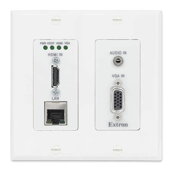
Page 16: Front Panel Connectors
NOTES: • The maximum HDMI cable length is 15 feet. Sleeve ( ) • Use an Extron LockIt lacing bracket to secure the HDMI connector to the 3.5 mm Stereo Plug Connector device (see HDMI Connection on page 11). (balanced) Analog audio input connector —... -
Page 17: Making Connections
Making Connections HDMI Connection Use an Extron LockIt Lacing Bracket to secure an HDMI cable to each connector. The following instructions describe how to attach one HDMI LockIt Lacing Bracket. For more stability, attach a second HDMI LockIt Lacing Bracket to the other mounting screw. -
Page 18: Tp Cable Termination And Recommendations
Brown Connector Figure 11. TP Cable Termination Supported cables The XTP T UWP 202 is compatible with shielded twisted pair (F/UTP, SF/UTP, and S/FTP) cable. ATTENTION: • Do not use Extron UTP23SF-4 Enhanced Skew-Free AV UTP cable or STP201 cable to link the XTP products. -
Page 19: Rs-232 And Ir Over Xtp Communication
The ideal length is 3/16 inch (5 mm). • Longer bare wires can short together. • Shorter wires are not as secure in the connectors and could be pulled out. XTP T UWP 202 Wallplate Transmitter • Installation and Operation... -
Page 20: Power Connection
Output Cord Figure 13. Power Wiring The XTP T UWP 202 can be connected to a local power supply. WARNING: Electric shock hazard. The two power cord wires must be kept separate while the power supply is plugged in. Remove power before wiring. -
Page 21: Remote Power
Remote power The XTP T UWP 202 can be powered remotely through an XTP Power Injector or through an XTP matrix switcher. ATTENTION: XTP remote power is intended for indoor use only. No part of the network that uses XTP remote power should be routed outdoors. -
Page 22: Operation
(see EDID Minder on page 34). The XTP T UWP 202 can record and save EDID in a user memory location, select a pre-defined EDID, or use EDID from a display connected to a receiver. EDID stored in the user memory location can come from the display connected to a receiver or a custom EDID imported through the XTP System Configuration Software. -
Page 23: Reset Modes
1 reset by NOT operate the firmware mistake, cycle power to the version that results from this device to return the firmware mode reset. version running prior to the reset. XTP T UWP 202 Wallplate Transmitter • Installation and Operation... -
Page 24: Sis Configuration And Control
To connect directly to an XTP T UWP 202, connect the computer to the XTP T UWP 202 through the front panel USB Config port or the rear panel RS-232 connector. The protocol for the serial port is as follows: 9600 baud, no parity, 8 data bits, 1 stop bit, no flow control. -
Page 25: Error Responses
Error Responses When the XTP T UWP 202 receives an SIS command and determines that it is valid, it performs the command and sends the corresponding response to the host device. If the command is determined invalid or contains invalid parameters, the switcher returns an error response to the host. -
Page 26: Command And Response Tables For Sis Commands
X& = Audio level adjustment –18 dB = default) = Black signal resolution = 720p @ 50 Hz = 720p @ 60 Hz (default) = 1080p @ 60 Hz XTP T UWP 202 Wallplate Transmitter • SIS Configuration and Control... -
Page 27: Picture Adjustment Commands (Analog Only)
NOTE: = Enable or disable = disable = enable (default) = Pixel phase = default) 0-255 = Horizontal or vertical shift = default) 0-65535 32768 = Preset number XTP T UWP 202 Wallplate Transmitter • SIS Configuration and Control... -
Page 28: Edid Commands
= Video signal status = video or TMDS not detected = video or TMDS detected = HDCP status = no source connected = HDCP compliant source = non-HDCP compliant source XTP T UWP 202 Wallplate Transmitter • SIS Configuration and Control... -
Page 29: Xtp System Configuration Software
Configuration Software This section contains installation and configuration procedures for the XTP System Configuration Software for configuring and controlling the XTP T UWP 202. It can also be controlled with SIS commands (see SIS Configuration and Control on page 18). Topics in... -
Page 30: Using The Xtp System Configuration Software
Using the XTP System Configuration Software The XTP T UWP 202 can be controlled directly from the front panel Config port or remotely from an XTP matrix switcher. Connections When opening the XTP System Configuration Software, the Connections screen opens first. -
Page 31: Top Menu
To access this menu, click the Tools menu. Tools Figure 21. Tools Menu NOTE: The options are not Backup and Restore Software Preference available when directly connected to the XTP T UWP 202. XTP T UWP 202 Wallplate Transmitter • XTP System Configuration Software... -
Page 32: Update Firmware
Select file from computer connected host device. The Browse dialog box opens. Select the desired firmware file and click the button. Open Click the button after the firmware finishes updating. Close XTP T UWP 202 Wallplate Transmitter • XTP System Configuration Software... - Page 33 Help menu menu contains a way to access XTP System Configuration Software information, Help a link to the help file, and a link to the Extron website. Figure 24. Help Menu NOTE: The option is not available when directly Tutorial (System Configuration) connected to the XTP T UWP 202.
-
Page 34: Device Settings
26) changes to reflect the currently selected input. NOTE: The signal indicators on the AV input buttons display green when a signal is present on the corresponding input or gray when there is no signal present. XTP T UWP 202 Wallplate Transmitter • XTP System Configuration Software... - Page 35 Auto-Image is applied whenever there is a change in the input sync. Auto Memory — Recalls input and image settings for signals that have previously been applied. When it is disabled, the XTP T UWP 202 treats every newly applied input as a new source.
- Page 36 Save Preset — To save a preset, select one from the list of presets and click the Save button. Preset Recall Preset — To recall a saved preset, select the desired preset from the list of presets and click the button. Recall Preset XTP T UWP 202 Wallplate Transmitter • XTP System Configuration Software...
- Page 37 Analog audio gain — Click and drag the handle of the slider, enter a value in the Gain field, or click the arrow to adjust the analog input gain. Down XTP T UWP 202 Wallplate Transmitter • XTP System Configuration Software...
- Page 38 Factory Reset settings except for firmware. NOTE: This is the same as the SIS command (see the System reset ZXXX command on page 22). XTP T UWP 202 Wallplate Transmitter • XTP System Configuration Software...
- Page 39 HDCP — Displays the HDCP status of input 2. Audio Information section Selected audio input — Displays the format of the currently selected audio input. Analog audio gain — Displays the analog audio gain in dB. XTP T UWP 202 Wallplate Transmitter • XTP System Configuration Software...
- Page 40 Favorites, Connected Outputs, or Available EDID panel (see figure 30, Below the list of inputs on the right side of the screen, click the button Assign to All (see figure 30, XTP T UWP 202 Wallplate Transmitter • XTP System Configuration Software...
- Page 41 Common tab appears, listing the EDID settings common among the selected outputs. Timings Select the desired common EDID setting. The EDID will be shown in the Available EDID panel. XTP T UWP 202 Wallplate Transmitter • XTP System Configuration Software...
-
Page 42: Reference Information
• Mounting Template Updating Firmware with Firmware Loader To upload and update firmware for the XTP T UWP 202, download the new firmware to a connected computer and upload the firmware with the Firmware Loader utility. Downloading Extron Firmware Loader Figure 33. -
Page 43: Installing Firmware Loader
Once Firmware Loader has been downloaded, run the .exe file from the location where the file was saved. The installation wizard window opens. Follow the instructions on the Installation Wizard screens to install Firmware Loader on the computer. XTP T UWP 202 Wallplate Transmitter • Reference Information... -
Page 44: Downloading Firmware
The file can be downloaded from the same page as the firmware. Click the link to the right of the desired device. Download Submit any required information to start the download. Note where the file is saved. XTP T UWP 202 Wallplate Transmitter • Reference Information... -
Page 45: Installing Firmware With Firmware Loader
Click the button to start the upload process. Begin Close Firmware Loader when the field shows , the Remaining Time 00.00.00 column is , and the field is Progress 100% Status completed XTP T UWP 202 Wallplate Transmitter • Reference Information... -
Page 46: Mounting Template
(7.78 cm) (10.87 cm) CUT-OUT AREA FOR WALL MOUNT Top Panel Figure 37. Mounting Template for 2-gang Mud Rings Please measure the printed template before cutting. NOTE: Measure the template before cutting. XTP T UWP 202 Wallplate Transmitter • Reference Information... - Page 47 Extron. NOTE: If a product is defective, please call Extron and ask for an Application Engineer to receive an RA (Return Authorization) number. This will begin the repair process.
Need help?
Do you have a question about the XTP T UWP 202 and is the answer not in the manual?
Questions and answers