
Subscribe to Our Youtube Channel
Related Manuals for Foxtech SurePulse VS


Summary of Contents for Foxtech SurePulse VS
- Page 1 MS600V2 Universal Multi-Spectral Camera User's Manual MS600 V2 MultiSpectral Camera User Manual (v1.0)
-
Page 2: Table Of Contents
MS600V2 Universal Multi-Spectral Camera User's Manual Content 1. Overview ..........................1 Use steps ......................... 2 2.1 Connection ........................2 2.1.1 Insert Micro SD card ....................2 2.1.2 Connect DLS module connection ................3 2.1.3 Power Connection ....................3 2.2 Use of cameras ......................4 2.2.1 Power on equipment .................... - Page 3 MS600V2 Universal Multi-Spectral Camera User's Manual 6.1 Mechanical interface ....................23 6.2 Electrical interface ....................24 6.2.1 Host interface ....................24 6.2.2 DLS interface ......................25 7. Parameter Description ....................26 Ending page ..........................29...
- Page 4 MS600V2 Universal Multi-Spectral Camera User's Manual Disclaimer Our company aims to provide high quality products, create value for customers, and maintain a serious and responsible attitude towards customers. In order to facilitate customers' understanding of our company and our better operation, our company carries out quality assurance and disclaimer on this: 1.We guarantee to provide customers with fully qualified products, if the product does have quality problems, after verification by our...
- Page 5 MS600V2 Universal Multi-Spectral Camera User's Manual Identification Note Note: Improper operation may result in improper use of the equipment, but it will not damage the equipment. Warning: Improper operation may result in improper use of the equipment, and may cause damage to the equipment. A description of the item, see the description will help to understand the content.
-
Page 6: Overview
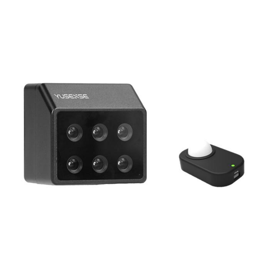
MS600V2 Universal Multi-Spectral Camera User's Manual 1. Overview MS600 series camera is a light,compact and professional multi-spectral camera available for drones, which includes 3 Version: MS600 V2, MS600 V2 Advanced and MS600 Pro. MS600 series camera has 6 multi-spectral sensors with 1.2Megapixels to recognize six specific bands of light including blue,green,red,dual red- edge,near infrared and capture invisible images to meet the needs of different industries such as crop condition monitoring,resource... -
Page 7: Use Steps
MS600V2 Universal Multi-Spectral Camera User's Manual 2. Use steps 2.1 Connection The cables needed to connect the camera including camera COMM cable, DLS cable, power cable, trigger cascade cable (if you do not use external trigger function, you may not connect this line). -
Page 8: Insert Micro Sd Card
MS600V2 Universal Multi-Spectral Camera User's Manual 2.1.1 Insert Micro SD card Ensure that the Micro SD card is inserted as shown below. Attention Micro SD card capacity not exceeding Max.128 GB; Micro SD card file format :exFAT/FAT32; Micro SD card write speed not less than 60 MB/s;... -
Page 9: Power Connection
MS600V2 Universal Multi-Spectral Camera User's Manual 2.1.2 DLS module Connection The Type-C interface of the DLS cable is first inserted into the CAM port of the DLS module, and the other end is connected with the camera COMM cable. For details, please refer to DLS 6.2.2 interface section. -
Page 10: Use Of Cameras
MS600V2 Universal Multi-Spectral Camera User's Manual Insert the camera COMM cable into the camera, as shown. Warning The camera supply voltage is 6 V~30 V, Considering that the power supply cable has a certain voltage drop, it is recommended that the minimum voltage should not be less than 7V, and the maximum voltage should not be higher than 30V, and ensure that the polarity is correct. - Page 11 MS600V2 Universal Multi-Spectral Camera User's Manual Status display Color Flashing Meaning frequency 10Hz System temperature is too high GPS not connected or GPS no signal DLS not connected 0.5 Hz SD card not inserted / SD card full capacity Always Software bright upgrade...
-
Page 12: Camera Configuration And Preview Display
MS600V2 Universal Multi-Spectral Camera User's Manual 3. Camera configuration and preview display Make sure that the camera has been plugged into the USB-WiFi module that comes with the camera, and then you can connect to the camera through any device with WiFi function, and configure the camera and preview the image through the device's browser. -
Page 13: Monitoring Page
MS600V2 Universal Multi-Spectral Camera User's Manual WEB configuration page includes four items: 3.2 Monitoring page This page provides the main status of the camera system, including: 1) Storage status: Micro SD card total capacity, residual capacity, working state information; 2) DLS status: DLS connection status, working status; 3) GPS status: current searching star number and signal quality;... -
Page 14: Settings Page
MS600V2 Universal Multi-Spectral Camera User's Manual 3.3 Settings page This page is used to configure the automatic capture mode of the camera, including timing trigger, overlap rate trigger, external trigger and so on. Attention After setting the automatic capture mode, the capture status and related parameters on the home page can be confirmed. -
Page 15: Timing Trigger Mode
MS600V2 Universal Multi-Spectral Camera User's Manual 3.3.1 Timing Trigger Mode 1) Auto capture mode drop-down menu select "timing trigger "; 2) Set timing trigger interval; 3) Set timing trigger enable height; 4) Save confirmation after setting up; 5) Start triggering. Attention After the timing trigger mode is set, the camera will start to trigger the photo after the aircraft takes off to the expected relative height, in order to... -
Page 16: Overlap Trigger Mode
MS600V2 Universal Multi-Spectral Camera User's Manual 3.3.2 Overlap Trigger Mode 1) Select "overlap rate trigger " in automatic capture mode drop- down menu ; 2) Enter the target flight altitude; 3) Enter the target flight velocity value; 4) Sets the course overlap rate of the two triggered images in drop- down menu ;... - Page 17 MS600V2 Universal Multi-Spectral Camera User's Manual Warning The altitude in overlap rate mode must be consistent with the altitude of the UAV when it executes the route, referring to the altitude relative to the UAV takeoff point, not altitude above sea level. In order to avoid the camera triggering to generate redundant image data during the drone's ascent or descending process, the camera will stop triggering when it is lower than the “set flight altitude (meters) minus 50...
-
Page 18: External Trigger Mode
MS600V2 Universal Multi-Spectral Camera User's Manual 3.3.3 The relationship between the course overlap and the speed-to-height ratio of the aircraft The minimum shooting interval of MS600 V2 multispectral camera is 1 second, the shooting interval is less than this value, the phenomenon of missed shooting will occur. -
Page 19: Cascade Trigger
MS600V2 Universal Multi-Spectral Camera User's Manual 1) PWM trigger mode also needs to set threshold time T, range 0<T <20ms ,PWM signal frequency range: 50 Hz-400Hz; 2) Confirm and save; 3) The external trigger function of the camera can be checked by setting the external trigger source. - Page 20 MS600V2 Universal Multi-Spectral Camera User's Manual strobe, SD card formatting, DLS information, calibration function, recovery of factory settings and other functions.
- Page 21 MS600V2 Universal Multi-Spectral Camera User's Manual Image Storage Format In advanced settings, you can set the camera storage format to 16 bit TIFF or JPG, the latter format can greatly reduce image volume, but will lead to image lossy compression. ...
- Page 22 MS600V2 Universal Multi-Spectral Camera User's Manual SD card formatting When the Micro SD card capacity is not sufficient or full, it can be directly formatted through this function. processing Completion status...
- Page 23 MS600V2 Universal Multi-Spectral Camera User's Manual Warning Perform SD card formatting, will clear all content in the Micro SD,which can not be restored. DLS information Click on the ‘DLS Information’ option to see the DLS serial number and software version number. ...
- Page 24 MS600V2 Universal Multi-Spectral Camera User's Manual...
-
Page 25: Preview Page
MS600V2 Universal Multi-Spectral Camera User's Manual Attention The third party compass should be used to check after calibration.It can be confirmed by comparing the angle in the "Flight Direction" column on the homepage. The corresponding true north direction should not exceed ±10°. If the error exceeds this value, it is recommended to recalibrate. -
Page 26: Preview Function
MS600V2 Universal Multi-Spectral Camera User's Manual 3.4.1 Preview function When you switch to this page, the preview enable button defaults , and when you click start,it will turn to , you will see an approximate real-time image (about 2 frames per second) of the corresponding band in the preview area, and the refresh count in the lower right corner will be updated continuously. - Page 27 MS600V2 Universal Multi-Spectral Camera User's Manual Preview Closed Preview opens Attention When there is no memory card or memory card is full, it can not be previewed; After setting any automatic capture mode, switch the preview page and turn on the preview enable button, automatically pause the automatic capture mode set before, exit the preview mode, automatically restore the automatic capture mode set before.
-
Page 28: Automatic Gray Board Shooting Function
MS600V2 Universal Multi-Spectral Camera User's Manual Attention Take pictures in the preview interface can be realized only when the preview mode is opened. 3.4.3 Automatic Gray Board shooting function The automatic gray board shooting function is added to prevent the overexposure problem of the gray board in extreme situations. It can automatically adjust the light and complete the gray board shooting. - Page 29 MS600V2 Universal Multi-Spectral Camera User's Manual period of time, when it prompts "Gray board automatic shooting succeeded", it means that the gray board was taken successfully and exited the automatic gray board shooting mode; when the "Gray board automatic shooting failed" was prompted, it indicated that the gray board was not successfully shot and exited the automatic gray board shooting mode.
-
Page 30: Manual Exposure Adjustment
MS600V2 Universal Multi-Spectral Camera User's Manual 3.4.4 Manual exposure adjustment Automatic capture mode drop-down selection off, while enabling manual exposure settings and save, switching to the preview page will see the corresponding manual adjustment of exposure time and gain options, Adjust exposure time and gain value after opening preview button will see brightness change of 6 channel images. -
Page 31: Planning Page
MS600V2 Universal Multi-Spectral Camera User's Manual Attention After setting and saving the automatic capture mode, the system sets the exposure function to automatic exposure, and the manual exposure automatically fails. Manual exposure settings need to be reconfigured after camera restart. 3.5 Planning page This page provides simple mission planning and evaluation functions. - Page 32 MS600V2 Universal Multi-Spectral Camera User's Manual The estimated flight time, image width, capture times and storage capacity can be obtained. Attention The evaluation results of the pre-flight estimator are for reference only. Please judge according to the actual situation and experience.
-
Page 33: File Storage
MS600V2 Universal Multi-Spectral Camera User's Manual 3.6 File storage After each camera is powered on, a new folder " MS600_SET_XXX " is automatically created in the storage card when the photo is triggered for the first time,the image is stored in the folder, when the folder is not deleted, the folder name serial number will be increased in turn. - Page 34 MS600V2 Universal Multi-Spectral Camera User's Manual multispectral image data more effectively and accurately, when planning route and trigger shooting, the following suggestions can be referred to: 1) Make sure the arrow of the DLS module direction is consistent with the flight direction; 2) Make sure the camera lens is clean before flight;...
- Page 35 MS600V2 Universal Multi-Spectral Camera User's Manual The course and side overlap rate is not less than 75%; 5) At least one route is beyond the edge of the planned flight area to ensure that the edge data is valid; 6) If accurate reflectivity data are required, gray board calibration should be carried out immediately before and after each flight.
-
Page 36: Firmware Upgrade
MS600V2 Universal Multi-Spectral Camera User's Manual Attention During the calibration process of the gray board, need to use the camera button on the WiFi preview page. When taking pictures, the gray board should occupy at least half of the camera's field of view, which can be judged by previewing the page. -
Page 37: Installation And Interface Definition
MS600V2 Universal Multi-Spectral Camera User's Manual The steps of the upgrade process are as follow: 1 ) Ensure that the DLS is properly connected with the camera; 2 ) Copy the upgrade package file (. bin format) to the card root directory;... - Page 38 MS600V2 Universal Multi-Spectral Camera User's Manual DLS module size as shown in the figure, can be fixed by 3M glue. 6.2 Electrical interface 6.2.1 Camera interface MS600V2 camera has an external connector interface, including power supply, external trigger, DLS power supply and communication, serial port, network port and other functions;1 USB 2.0 interface for USB-WiFi module;1 MicroSD card interface.
- Page 39 MS600V2 Universal Multi-Spectral Camera User's Manual Connector Name: External Connector Node Definition Note Description PIN1 Signal ground PIN2 NET_TRXN3 Brown (not connected) PIN3 NET_TRXP3 Brown white (not connected) PIN4 NET_TRXN2 Blue (not connected) PIN5 NET_TRXP2 Blue and white (not connected) Net port PIN6 NET_TRXN1...
- Page 40 MS600V2 Universal Multi-Spectral Camera User's Manual SM31B-SHLVS-G-TB Recommendation AWG28 Wire Fit connector plug Attention If the GND of trigger signal is different from the power supply GND, must not to connect GND only at the camera. 6.2.2 D LS interface The MS600V2 DLS has two external connector interfaces: camera connection, third party GPS connection interface;...
- Page 41 MS600V2 Universal Multi-Spectral Camera User's Manual Connector Name: CAM (Camera Connection Interface) A face B face Definition Definition Description Signal/power ground DLS supply ,5 V 3.3 V Level UART 3.3 V Level UART DLS power supply ,5 V Signal/power ground Type specification Type-C Connector...
- Page 42 MS600V2 Universal Multi-Spectral Camera User's Manual 7. Parameter Description Basic parameters table...
- Page 43 MS600V2 Universal Multi-Spectral Camera User's Manual 17 optional band configurations, as shown in the table below. Band Configuration Bandwidth Tiff band name Central (FWHM) wavelength Blue (blue) 410nm 35 nm Blue (blue) 450 nm * 35 nm Green (green) 490nm 25 nm Green (green) 530nm...
Need help?
Do you have a question about the SurePulse VS and is the answer not in the manual?
Questions and answers