Advertisement
Quick Links
Advertisement

Subscribe to Our Youtube Channel
Related Manuals for Foxtech SYK-30


Summary of Contents for Foxtech SYK-30
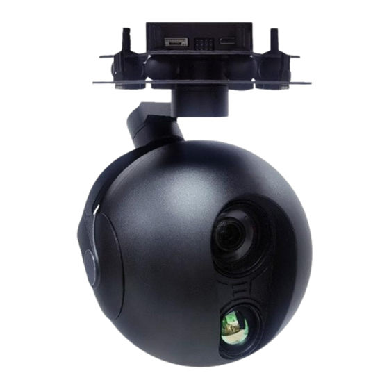
- Page 1 User Manual SYK-30 AI-TIR EO/IR Dual Sensor Camera With 3-axis Gimbal...
-
Page 2: Table Of Contents
Content Warning and disclaimer ....................... 2 Brief Introduction ...........................3 Packing List ............................4 Connection Pin Description ......................5 Drawing and mounting hole diagram ..................6 Installation and network ......................8 Technical specification ........................9 Serial Command Protocol ......................10 Warning and disclaimer... -
Page 3: Brief Introduction
In any cases ( not matter power on or not ) avoid aiming the camera at extremely high-temperature radiation source (e.g. the sun), or else the sensor is likely to be damaged. Be sure not to adjust the pod or change its mechanical structure, installing the pod on the aircraft before power on. -
Page 4: Packing List
Thermal gimbal camera can be widely used in public security, firefighting, electricity and other UAV applications, equipped with infrared thermal imaging camera with extended feature for temperature measurement function, also can save thermal imaging video and pictures on the front end. This equipment is used for mounting on the aircraft, which can achieve stabilization in three directions of yaw, roll and pitch direction, and adopt the integrated design of shock absorption and pod, which can greatly reduce... -
Page 5: Connection Pin Description
Connection Pin Description 1)RJ-TX+、RJ-TX- 、RJ-RX+ 、RJ-RX- for Ethernet,RJ-TX+ and RJ-TX- are pairs, RJ-RX and RJ-RX- are pairs. 2)undefined for undefined pin. 3)GND for ground. 4)TX and RX for Serial command control. 5)SBUS for connection with SBUS signal receiver. 6)5V for out DC5v signal, use together with GND,for SUBUS receiver power. 7)Mini HDMI interface for output video. -
Page 6: Drawing And Mounting Hole Diagram
Drawing and mounting hole diagram... - Page 7 Connection with flying platform...
-
Page 8: Installation And Network
Installation and network 1 Preparation 1.1 HDMI HD image transmission(1080P) or Network port HD image transmission is a must 1.2 Choose the communication mode of the control pod, the pod can be controlled by S.BUS, serial port and network, serial port and network need to develop the corresponding software through the protocol by user. -
Page 9: Technical Specification
Technical specification SYK-30 AI-TIR EO/IR Weight 1100g Dimension 144mm×135mm×205mm ( L×W×H ) Operating voltage 3s~6s Operating current Static:600mA(@12V);Dynamic:3000mA(@12V) Pitch Upward 15°,downward 90° Roll ±40° ±155°(360°Ethernet Version Only ) Angle Jitter ±0.01° Control interface S.BUS or TTL Camera(Thermal+Visible) Camera Thermal Visible... -
Page 10: Serial Command Protocol
Serial Command Protocol 1. Send within 15 seconds after power on: EF 05 00 04 02 A0 4D 4D 4D 12 22, Need to send more than 20 times, 1-10hz, baud rate 115200, 8 bit data, 1 bit stop, no parity. - Page 11 Down rotation :EF 0F 00 04 02 A3 11 05 DC 06 40 05 DC 05 DC 05 DC 05 DC 04 BC Up rotation :EF 0F 00 04 02 A3 11 05 DC 05 70 05 DC 05 DC 05 DC 05 DC 04 EB Right rotation :EF 0F 00 04 02 A3 11 05 DC 05 DC 05 70 05 DC 05 DC 05 DC 04 EB Left rotation :EF 0F 00 04 02 A3 11 05 DC 05 DC 06 40 05 DC 05 DC 05 DC 04 BC Stop rotaion :EF 0F 00 04 02 A3 11 00 00 05 DC 05 DC 05 DC 05 DC 05 DC 04 76...
- Page 12 4.Pass-Through protocol The pass-through transmission protocol is a one-way serial port " pass-through protocol" that is input from the external serial port of the YAW board, and the external output of the PITCH board, which is generally used for the customer's custom control of the camera core.
- Page 13 Red alarm: f8 00 12 02 09 00 00 1d Black hot: f8 00 12 02 0b 00 00 1f Snapshot/recording: JPEG snapshot: f8 00 80 01 00 00 00 81 Recording: f8 00 82 01 00 01 00 84 Stop recording: f8 00 84 01 00 01 00 86 Temperature data snapshot:...
Need help?
Do you have a question about the SYK-30 and is the answer not in the manual?
Questions and answers