Table of Contents
Advertisement
Quick Links
Instruction Manual
Universal Fieldbus Gateway
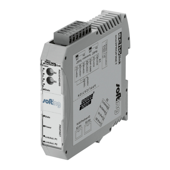
echolink one2PROFINET
Softing Industrial Automation GmbH | Richard-Reitzner-Allee 6 | 85540 Haar, Germany
Tel:+49 89 45656-0 | Fax: +49 89 45656-399 | http://industrial.softing.com |
E-Mail: info.automation@softing.com | Support: support.automation@softing.com
Advertisement
Table of Contents

Subscribe to Our Youtube Channel
Related Manuals for Softing echolink one2PROFINET


Summary of Contents for Softing echolink one2PROFINET
- Page 1 Instruction Manual Universal Fieldbus Gateway echolink one2PROFINET Softing Industrial Automation GmbH | Richard-Reitzner-Allee 6 | 85540 Haar, Germany Tel:+49 89 45656-0 | Fax: +49 89 45656-399 | http://industrial.softing.com | E-Mail: info.automation@softing.com | Support: support.automation@softing.com...
-
Page 2: Table Of Contents
8.3.2 Protocol definitions ....... 19 15.1.15 echolink one2PROFINET V. 1.0... - Page 3 Hardware ports, switches and LEDs ....42 Device labeling ......42 echolink one2PROFINET V. 1.0 15.1.15...
- Page 4 13.3 Installation ....... . . 53 13.4 Dimensional drawing echolink one2PROFINET ... . . 53 13.5 Commissioning .
- Page 5 14 Appendix ....... . . 56 14.1 Hexadecimal table ......56 echolink one2PROFINET V. 1.0 15.1.15...
- Page 6 Tel: + 49 89 4 56 56-0 Fax: + 49 89 4 56 56-488 Internet: http://industrial.softing.com Email: info.automation@softing.com Support: support.automation@softing.com The latest version of this manual is available in the Softing download area at: http://industrial.softing.com. 15.1.15 echolink one2PROFINET V. 1.0...
-
Page 7: Information On Ce Marking Of The Module
The EU Declarations of Conformity are available at the following location for perusal by the responsible authorities in accordance with the EU Directive, Article 10: Softing Industrial Automation GmbH, Richard-Reitzner-Allee 6, 85540 Haar, Germany. Scope of application The modules are designed for use in the industrial sector and comply with the following... -
Page 8: Information For The Machine Manufacturers
"machine" is taken to mean a totality of connected parts or fixtures (see also EN 292-1, Para- graph 3.1) The module is a part of the electrical equipment of the machine and must thus be included by the machine manufacturer in the Declaration of Conformity process. 15.1.15 echolink one2PROFINET V. 1.0... -
Page 9: Introduction
Softing Industrial Automation GmbH Introduction The echolink one2PROFINET module serves to adapt a serial port to PROFINET networks. The device features 2 PROFINET ports - one port can for instance be used as an outgoing PROFINET port. Talking of PROFINET is automatically connected with the 100 Mb/s-version, full-duplex and switched Ethernet. -
Page 10: Echolink One Software Flow-Chart
Softing Industrial Automation GmbH Introduction echolink one software flow-chart 15.1.15 echolink one2PROFINET V. 1.0... -
Page 11: Echolink One Application Diagram
Introduction Softing Industrial Automation GmbH echolink one application diagram The following graph shows a typical connection scheme. echolink one2PROFINET V. 1.0 15.1.15... -
Page 12: Operation Modes Of The Gateway
RS-side of the Gateway and the fieldbus is possible. As long as the Gateway is not in the config- uration mode or the test mode, the data exchange mode is active. In the data exchange mode the Gateway will execute the downloaded Script. 15.1.15 echolink one2PROFINET V. 1.0... -
Page 13: Rs-Interface
RS-interface RS-interfaces at the echolink one The echolink one2PROFINET has the interfaces RS232, RS422 and RS485 available. Buffer sizes at the echolink one echolink one features at the serial side a buffer with the size of 1024 bytes for input data and out- put data each. -
Page 14: Ssi-Interface
Low for at least one bit. If the echolink one does NOT detect this bit on Low, error 12 is issued. For example it can detect a cable break or a not connected encoder. However, it can also be a misconfigured bit length, or a too slow read out clock. 15.1.15 echolink one2PROFINET V. 1.0... -
Page 15: Hardware-Wiring
X1 (3pin + 4pin screw-plug-connector): Pin no. Name Function at SSI Rx 232 n. c. Tx 232 n. c. AP-GND n. c. Rx 422+ SSI DAT+ Rx 422- SSI DAT- Tx 422+ SSI CLK+ Tx 422- SSI CLK- echolink one2PROFINET V. 1.0 15.1.15... -
Page 16: Mode Of Operation Of The System
Communication can be split into seven layers, Layer 1 to Layer 7, in accordance with the ISO/OSI model. The Softing AG Gateways convert Layers 1 and 2 of the customized bus system (RS485 / RS232 / RS422) to the corresponding Fieldbus system. Layers 3 and 4 are being covered by the UDP/IP-protocol, TCP/IP-protocol. -
Page 17: Implemented Protocols In Echolink One
RS422 and RS485 though! 8.2.1 Data structure 8.2.2 Fieldbus parameters Trigger byte: See "The trigger byte", Chapter 8.5‚ on page 22 Length byte: See "The length byte", Chapter 8.6‚ on page 22 echolink one2PROFINET V. 1.0 15.1.15... -
Page 18: Rs232 Parameter Table
If less have been received, padding with 0 occurs. If the "Length byte" is active, the number of received useful data items is entered there. If the, "Trigger byte" is active, this is incre- mented by one after each complete reception operation at the RS interface. 15.1.15 echolink one2PROFINET V. 1.0... -
Page 19: Protocol: 3964(R)
If the 3964 R driver receives data, it monitors arrival of the individual characters within period tz. If no character is received within the timeout time, the protocol terminates transfer. No acknowledgement is sent to the coupling partner. echolink one2PROFINET V. 1.0 15.1.15... -
Page 20: Retries
Modbus only when this byte has changed. In the reverse direction (to the fieldbus), the gateway transfers the number of received Modbus data records in this byte, i.e. this byte is incremented by the gateway after each data record. 15.1.15 echolink one2PROFINET V. 1.0... -
Page 21: Data Structure
- but since the fieldbus requires a fixed data length, this must be preset by means of a selection in the GSDML file. This length should be selected by the user such that the longest Modbus request resp. response can be processed. 8.4.3.2 Data structure echolink one2PROFINET V. 1.0 15.1.15... -
Page 22: Communication Sequence
Protocol „Universal Modbus RTU Slave“ The echolink one a Modbus slave on the application side. The slave ID is set with the rotary coding switches S4 + S5 (S4 = High, S5 = Low). 15.1.15 echolink one2PROFINET V. 1.0... -
Page 23: Data Structure On The Fieldbus Side E.g.: Profibus
Start-Address 0001, Length 56 (38h), FC1 (-Read Coil Status) [01] [01] [00] [00] [00] [38] [3d] [d8] echolink one sends response via RS232/485: [01] [01] [07] [01] [02] [03] [04] [05] [06] [07] [6b] [c5] echolink one2PROFINET V. 1.0 15.1.15... -
Page 24: Example: Fc3 (Read Holding Register) + Fc4 (Read Input Register)
07 01 02 03 04 05 06 07 08 09 0A 0B 0C 0D 0E 0F 10 11 12 13 14 15 16 17 18 19 1A 20 20 20... Byte = Fieldbus length byte 15.1.15 echolink one2PROFINET V. 1.0... - Page 25 The user data (internal buffer) is no bigger than1024 byte. In the following example the Bit (Coil) in Address 0002 is set to High (1): The fieldbus data is updated: 02 03 04 05 06 07 00 00 00 00 00 echolink one2PROFINET V. 1.0 15.1.15...
-
Page 26: Example: Write Single Register Fc6
Note: The address can only be passed in multiples of 8 incl. Null. Also 0, 8, 16, … (Here you also have to keep in mind the offset of 1) Example: Start address = 0001. 15.1.15 echolink one2PROFINET V. 1.0... -
Page 27: Example: Preset Multiple Register Fc16
The echolink one is Modbus-Master on the Application side. 8.8.1 Data structure Fieldbus side (e.g. PROFIBUS): Applies to In and Out Byte: Trigger-Byte, not changeable (see chapter 8.5, The trigger byte) Byte: Fieldbus length byte, not changeable (see chapter 8.6, The length byte) echolink one2PROFINET V. 1.0 15.1.15... -
Page 28: Data Structure Application Side
FC 1 + 2 as well as FC 3 + 4 are principally the same, the only difference is the definition of the start address. At FC1 it starts at Null, at FC2 at 10 000. At FC3 it starts at 40 000, at FC4 at 30 000 15.1.15 echolink one2PROFINET V. 1.0... -
Page 29: Configuration: Via Wingate Since Wcf Datei Version 396
„(Byte)“: Counting in bytes, starting at the position Null. Attention: For read commands, e.g. FC3, after the trigger- and lenghtbyte the first process value is the postion nulll, which is copied to the fieldbus to the PLC. For write commands, e.g. FC16, the position Null is the trigger byte. echolink one2PROFINET V. 1.0 15.1.15... -
Page 30: Example: Read Coil Status Fc1
Byte = Fieldbus Map Adr 6 (value = 0x01) see configuration Byte = Fieldbus Map Adr 7 (value = 0x00) Byte … In the following example the value in address 6 in the Modbus Master is changed from 0 to 1. 15.1.15 echolink one2PROFINET V. 1.0... -
Page 31: Example: Read Input Status Fc2
The following example shows the content of address 10007 ... 10009 is mapped/copied into the 8. fieldbus output byte. 76 09 00 00 00 00 00 00 00 00 01 00 00 00 00 echolink one2PROFINET V. 1.0 15.1.15... -
Page 32: Example: Read Multiple Register Fc3
(RX Poll Retry = 0) one time via the RS interface, and waits a maximum of 250 ms (Modbus Timeout = 25) on the response. Fieldbus Map Adr = 0 -> not activ 15.1.15 echolink one2PROFINET V. 1.0... -
Page 33: Example: Read Input Registers Fc4
At FC5 a bit is set in the Modbus slave, if the mapped fieldbus byte is bigger (>) than NULL. Modbus Slave(impact)SPS sends Configuration Fieldbus data (reason) Note: No. of Points is not required Another example for when a second request is configured: echolink one2PROFINET V. 1.0 15.1.15... -
Page 34: Example: Preset Single Register Fc6
0E 00 FF 05 00 00 00 00 00 00 00 00 00 00 00 00 00 00 00 00 00 00 00 00 00 00 00 00 00 00... echolink one sends request: [01] [0f] [00] [02] [00] [0a] [02] [ff] [05] [65] [29] Modbus Slave sends response: [01] [0f] [00] [02] [00] [0a] [74] [0c] Storage content of Modbus Slave after response: 15.1.15 echolink one2PROFINET V. 1.0... -
Page 35: Example: Preset Multiple Register Fc16
[01] [10] [00] [02] [00] [0a] [14] [01] [02] [03] [04] [05] [06] [07] [08] [09] [0a] [0b] [0c] [0d] [0e] [0f]... [10] [11] [12] [13] [14] [3d] [e4] Modbus Slave sends Response: [01] [10] [00] [02] [00] [0a] [e1] [ce] Storage content Modbus Slave to Response: echolink one2PROFINET V. 1.0 15.1.15... -
Page 36: Protocol „Universal Modbus Ascii Master/Slave
The fieldbus data exchange for Modbus ASCII is identical with RTU. The echolink one automati- cally transmits the data in ASCII format on the serial side. 8.9.1 Appendix 8.9.1.1 Example Configuration 1: Hardware echolink one 15.1.15 echolink one2PROFINET V. 1.0... - Page 37 Implemented protocols in echolink one Softing Industrial Automation GmbH PROFIBUS Master sends and receives: echolink one2PROFINET V. 1.0 15.1.15...
-
Page 38: Swap Word
Modbus Slave storage content: 8.9.1.2 Swap Word Configuration with „Swap Word“ = enabled. Fieldbus data is swapped to the Modbus slave. Mea- ning High Byte and Low Byte are switched. Fieldbus Master sends and receives. 15.1.15 echolink one2PROFINET V. 1.0... - Page 39 Implemented protocols in echolink one Softing Industrial Automation GmbH The swapping is bidirectional Modbus Slave Data content echolink one2PROFINET V. 1.0 15.1.15...
-
Page 40: Example With Fast Ethernet
Softing Industrial Automation GmbH Implemented protocols in echolink one 8.9.1.3 Example with Fast Ethernet 15.1.15 echolink one2PROFINET V. 1.0... - Page 41 Implemented protocols in echolink one Softing Industrial Automation GmbH echolink one2PROFINET V. 1.0 15.1.15...
-
Page 42: Hardware Ports, Switches And Leds
Rx 422- (485-) Receive signal Tx 422+ (485+) Transmit signal Tx 422- (485-) Transmit signal For the operation at a 485-interface the two pins labeled "485-" have to be connected together. Also the two pins "485+". 15.1.15 echolink one2PROFINET V. 1.0... -
Page 43: Connector Supply Voltage And Debug-Interface
Please note that the devices of the series echolink one should not be operated with AC voltage. LEDs The Gateway echolink one2PROFINET features 10 LEDs with the following significance: LED (PROFINET) Power green Supply voltage PROFINET (total device) LED Link / Act. -
Page 44: Led "Link / Act. P1
LEDs 1 / 2 / 4 / 8 (Error No. / Select ID) If these 4 LEDs flash and LED “State“ simultaneously lights red, the error number is displayed in binary notation (conversion table, see Annex) in accordance with the table in chapter "Error handling". 15.1.15 echolink one2PROFINET V. 1.0... -
Page 45: Switches
This value is read in when the Gateway is switched on. The switch positions "EE" (testmode) and "FF" (config mode) are not possible for RS422- or RS485-operation. Note: The switch position "DD" (ie, S4 and S5 in position "D") is reserved for internal purposes. echolink one2PROFINET V. 1.0 15.1.15... -
Page 46: Error Handling
Script error Reserved RS-transmit buffer overflow RS-receive buffer overflow RS timeout General fieldbus error Parity-or frame-check-error Reserved Fieldbus configuration error Fieldbus data buffer overflow Reserved Table 1: Error handling at echolink one - system errors. 15.1.15 echolink one2PROFINET V. 1.0... - Page 47 Modbus RTU Master Modbus (ASCII) Exchange, e.g. Modbus ASCII Master Checksum error Modbus RTU Slave Exception Response internal error at process data all Protocols measurement Table 2: Protocol based errors *Flashing frequency = 0,5 Hertz echolink one2PROFINET V. 1.0 15.1.15...
-
Page 48: Installation Guidelines
Connect the supply voltage to the 4-pole plug-in screw terminal in accordance with the labelling on the device. 11.2.1.2 Equipotential bonding connection The connection to the potential equalization automatically takes place it is put on the DIN-rail. 15.1.15 echolink one2PROFINET V. 1.0... -
Page 49: Profinet-Io Communication Interface
Interference currents on cable shields are discharged to earth via the shielding bus which is con- nected conductively to the chassis or housing. A low-impedance connection to the PE wire is particularly important in order to prevent these interference currents themselves becoming an interference source. echolink one2PROFINET V. 1.0 15.1.15... - Page 50 Downstream of the entry point of the line into the cabinet, connect the shield to a shielding bus. Continue the shield as far as the module, but do not connect it again at this point! 15.1.15 echolink one2PROFINET V. 1.0...
-
Page 51: Technical Data
Reverse voltage protection But does not function! Short-circuit protection Overload protection Poly-switch Thermal fuse 9 V DC Undervoltage detection (USP) 5 ms Emergency power supply Device fully operable Table: Technical data of the module echolink one2PROFINET V. 1.0 15.1.15... -
Page 52: Interface Data
- 0.2 ... + 0.2 V - Logic level Transmit pause (MARK): - Voltage level - 3 ... –15 V + 1.5 ... +5 V - Logic level Table: Technical data of the interfaces at the module 15.1.15 echolink one2PROFINET V. 1.0... -
Page 53: Commissioning Guide
13.3 Installation The echolink one2PROFINET module features protection type IP20 and is thus suitable for switch cabinet use. The device is designed for snapping onto a 35 mm DIN-rail. 13.4 Dimensional drawing echolink one2PROFINET 13.5 Commissioning... -
Page 54: Profinet Address-Assignment
13.12 Project planning Use any project planning tool for project planning. If the required GSD file was not supplied with your project planning tool, a sample file can be found on the Internet under http://industrial.softing.com. 15.1.15 echolink one2PROFINET V. 1.0... - Page 55 PROFINET. The book (in German) can be ordered from the PROFIBUS User Organisation, Order No. 4.181. Address: PROFIBUS Nutzerorganisation e.V. Haid-und-Neu-Str. 7 D-76131 Karlsruhe Germany Tel: +49 (0) 721 9658 590 echolink one2PROFINET V. 1.0 15.1.15...
- Page 56 Softing Industrial Automation GmbH Appendix 14 Appendix 14.1 Hexadecimal table Decimal Binary 0000 0001 0010 0011 0100 0101 0110 0111 1000 1001 1010 1011 1100 1101 1110 1111 15.1.15 echolink one2PROFINET V. 1.0...
- Page 57 Appendix Softing Industrial Automation GmbH echolink one2PROFINET V. 1.0 15.1.15...
- Page 58 Softing Industrial Automation GmbH Appendix 15.1.15 echolink one2PROFINET V. 1.0...
- Page 59 Appendix Softing Industrial Automation GmbH echolink one2PROFINET V. 1.0 15.1.15...
- Page 60 Richard-Reitzner-Allee 685540 Haar / Germany Tel: + 49 89 4 56 56-0 Fax: + 49 89 4 56 56-488 Internet: http://industrial.softing.com Email: info.automation@softing.com Support: support.automation@softing.com The latest version of this manual is available in the Softing download area at: http://industrial.softing.com.
Need help?
Do you have a question about the echolink one2PROFINET and is the answer not in the manual?
Questions and answers