Advertisement
Quick Links
Advertisement

Related Manuals for Softing pnGate DP


Summary of Contents for Softing pnGate DP
- Page 1 User Guide PROFINET Gateways Version: EN-042020-1.30 © Softing Industrial Automation GmbH...
- Page 2 The information contained in these instructions corresponds to the technical status at the time of printing of it and is passed on with the best of our knowledge. Softing does not warrant that this document is error free. The information in these instructions is in no event a basis for warranty claims or contractual agreements concerning the described products, and may especially not be deemed as warranty concerning the quality and durability pursuant to Sec.
- Page 3 Mounting and dismounting ......................9 3.1.2 Connection diagrams pnGate PA ......................10 3.1.3 Connection diagram pnGate PB ......................11 3.1.4 Connection diagram pnGate DP ......................11 3.1.5 Connecting the power supply ......................12 3.1.6 Connecting to the network ......................13 3.1.7 Installation positions ......................
- Page 4 Table of Contents 4.7.3 Creating a new project in Siemens TIA Portal ......................26 4.7.4 Updating and uploading a GSDML file ......................31 Generic GSDML 4.7.4.1 ..................... 31 GSDML 4.7.4.2 ..................... 31 Device catalog update in TIA portal 4.7.4.3 ..................... 31 4.7.5 Switching from a 2-channel to a 4-channel gateway ......................
- Page 5 About this guide Read me first Please read this guide carefully before using the device to ensure safe and proper use. Softing does not assume any liability for damages due to improper installation or operation of this product. This document is not warranted to be error-free. The information contained in this document is subject to change without prior notice.
- Page 6 You can write your comments and suggestions to the PDF file using the editing tool in Adobe Reader and email your feedback to support.automation@softing.com. If you prefer to write your feedback directly as an email, please include the following information with...
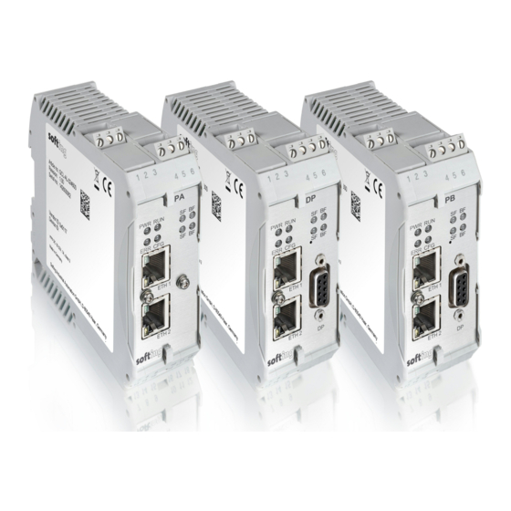
- Page 7 The pnGate PB integrates PROFIBUS DP (Decentralised Peripherals) networks in PROFINET systems at speeds of up to 12Mbit/s, typically via a centralized controller in factory automation. The pnGate DP integrates one PROFIBUS DP (Decentralised Peripherals) network with up to 32 PROFIBUS DP devices in Modbus systems at speeds of up to 12Mbit/s.
- Page 8 PROFINET Gateways - User Guide Supported features The PROFINET Gateway maps PROFIBUS devices to PROFINET networks. All gateways support the conversion of PROFIBUS GSD files into a single PROFINET GSDML using an integrated web-based conversion tool.Other supported features include: Simple connection to PROFIBUS PA and PROFIBUS DP devices using PROFINET controllers Integration in FDT frame applications Integration in Siemens SIMATIC PDM Configuration of the gateway in a web browser...
- Page 9 Chapter 3 - Installation Installation Hardware installation Note With an ambient temperature above 55 °C at the place of installation connecting cables may heat up strongly if they are installed in an unfavourable position. In such cases, ensure that the permissible service temperature of the cables (i.e.
- Page 10 PROFINET Gateways - User Guide 3.1.2 Connection diagrams pnGate PA The following diagram shows the input and output interfaces of the pnGate PA. The 2-channel model has 2 physical PROFIBUS segment connections (PA0 to PA1), while the 4-channel model has 4 physical PROFIBUS segment connections (PA0 to PA3).
- Page 11 3.1.4 Connection diagram pnGate DP The following diagram shows the input and output interfaces of the pnGate DP. The gateway has two 10/100 Base-T Ethernet ports (ETH1/ETH2) and one RS-485 link for PROFIBUS DP data communication. The RJ45 ports correspond to IEEE 802.3 and are connected to an internal switch for line topologies.
- Page 12 Protective Earth (PE) of the system. Note As the connection diagrams show, the power can also be applied by a special DIN rail connector (Rail Power Supply). For further information contact Softing Industrial Automation GmbH. Note See also the maximum ambient temperatures in the Section Installation positions Version EN-042020-1.30...
- Page 13 Chapter 3 - Installation 3.1.6 Connecting to the network 1. Connect each segment of your PROFIBUS network to a port of your gateway. Be sure that each segment is powered by a power conditioner. If you connect to field devices in explosive atmospheres ensure that you also connect a field barrier in between.
- Page 14 PROFINET Gateways - User Guide pnGate DP network topology 3.1.7 Installation positions PROFINET Gateways can be mounted horizontally and vertically. Depending on the installation position, different ambient operating temperatures (T ) are allowed. Minimum distance Provide a minimum distance of 50 mm to the air inlet and air outlet to ensure natural convection.
- Page 15 0 - 4 32VDC 17.5 mm 60 °C 0 - 2* 24VDC 17.5 mm 60 °C pnGate DP models have no PA channel Vertical installation position and maximum temperatures Number of PA Maximum PA fieldbus Minimum distance Maximum ambient channels used voltage...
- Page 16 PROFINET Gateways - User Guide 3.1.8 Powering up the device Turn on the power supply. The boot process will take around 15 seconds. For indication of proper operation refer to LED status indicators Version EN-042020-1.30...
- Page 17 Software installation Note When you install a Softing product for the first time, you will be asked if you trust the publisher. Activate the option Always trust software from Softing AG if you do not want to be asked in subsequent installations and select [Install] to start the installation.
- Page 18 Area Network. Searching for devices The following steps apply to Windows 10. 1. Click Start Softing Search and Configure. The application window is opened. 2. Open the Network Adapter Selection. 3. Select the network on which you want to search for the connected gateway.
- Page 19 Chapter 4 - Configuration 5. Select the network device you want to configure. 6. Click [Configure] or double-click the device. The configuration window opens. Here you can modify all relevant values. Note If you are starting the connected PROFINET Gateway for the first time and you have not yet assigned user roles for the gateway, the user name in the configuration window is preset to administrator.
- Page 20 PROFINET Gateways - User Guide Setting the IP address of the PC If you have not changed the IP address of a PROFINET Gateway as described in the previous Section will need to configure the IP address of your PC to access the gateway from your PC. The following chapter describes how to set a static IP address in Windows 10.
- Page 21 Chapter 4 - Configuration Login to user interface 1. Open your Internet browser and enter the IP address of your gateway. Note If you don't recall the IP address of your gateway, start the tool to find out what it is (see Step 2 below).
- Page 22 FS-QsHnc7BWa{6w<). Both <fJ#\/$eB2qtGd*) Softing Support purposes. Note It is strongly recommended to change the Diagnostics and Expert passwords immediately by entering the user name in the input field instead of selecting one of the icons above.
- Page 23 Chapter 4 - Configuration The following table shows the permissions/actions of each user role: Permission Administrator Service Engineer Observer Setting password Configuring gateway Reading configuration Reading diagnostics Updating firmware Resetting gateway Installing HTTPS certificates Version EN-042020-1.30...
- Page 24 Click [Update] to download the firmware file and to reboot the system. The system performs a firmware file check. The download starts automatically. When the download is completed the pnGate PA/pnGate PB/pnGate DP will be rebooted. When the boot process is completed, the RUN LED is ON.
- Page 25 Chapter 4 - Configuration PROFINET configuration in the TIA Portal The following chapter describes how to convert the GSD file of a PROFIBUS PA or PROFIBUS DP field device to a GSDML using the built-in PROFIBUS configurator and how to use this file to configure a PROFINET device in the Siemens TIA Portal (Totally Integrated Automation Portal).
- Page 26 9. Double-click [Devices & Networks] to open the Network View. 10. Open the Hardware Catalog. 11. Select Other field devices PROFINET IO Gateway Softing Industrial Automation GmbH Softing Process Automation Gateways. 12. Select the project name you entered in Step 3. Version EN-042020-1.30...
- Page 27 Chapter 4 - Configuration 13. Select DAP. 14. Select Version in the information dialog to identify the correct GSDML by date and time stamp. 15. Select the gateway, drag it from the Hardware Catalog and drop it into the Network View. 16.
- Page 28 PROFINET Gateways - User Guide 19. Drag a module to a free slot. The supported submodules are shown under Submodules. 20. Click the gray device symbol and select a submodule (e.g. temperature value) from the catalog to open the corresponding Properties dialog (configure the parameters of the submodule if required - similar to PA Function Block).
- Page 29 Chapter 4 - Configuration 23. Select the default PROFINET IP address settings or click the gateway to configure these settings in Properties General. Note Do NOT to use the same IP address for the gateway and the device's web server. Example: 192.168.0.10 is the web server's default address.
- Page 30 PROFINET Gateways - User Guide 24. Save the project and download it to the device. 25. Select the corresponding PC network interface where the controller is connected. 26. Click [Load] and [Finish] to complete the setup. A confirmation window appears displaying the message Downloading to device completed without error.
- Page 31 2. Select the existing PROFINET gateway device in the Hardware Catalog under Other field devices PROFINET IO Gateway Softing Industrial Automation GmbH Softing Process Automation Gateways. 3. Import the new GSDML which you can identify by the date and time string in the file name.
- Page 32 PROFINET Gateways - User Guide 6. Click the [Change revision] button in the Catalog information window. 7. Select the GSDML file imported in Step 3 (check date and time string) in the new window that appears. 8. Instantiate the new PA device module and assign the correct parameter to the new device if you imported a generic GSDML.
- Page 33 2. Select the existing PROFINET gateway device in the Hardware Catalog under Other field devices PROFINET IO Gateway Softing Industrial Automation GmbH Softing Process Automation Gateways. 3. Import the new GSDML file which you can identify by the date and time string in the file name.
- Page 34 PROFINET Gateways - User Guide 6. Remove the 2-channel FAP module (Fieldbus Access Port) from the selected gateway. The FAP module is always located in slot 1. 7. Click the [Change revision] button in the Catalog information window. 8. Select the GSDML file imported in Step 3 (check date and time string) in the new window that appears. 9.
- Page 35 Setting the IP address of the PC PACTware 4.1 or any other FDT frame application is installed. PROFIdtm is installed. Hint If you have downloaded PACTware from the product website, the Softing PROFIdtm is included but must be installed separately. Version EN-042020-1.30...
- Page 36 3. Allow Windows User Account Control (UAC) to modify settings. The PROFIBUS Control Panel is opened. 4. Select a PROFINET Gateway (pnGate PA/pnGate PB/pnGate DP). 5. Click [Add...] and enter a symbolic node name (default value is Node0). 6. Click [Next] and enter the IP address of the PROFINET Gateway in interface name field of the next window.
- Page 37 Chapter 4 - Configuration 4.8.3 Creating a project in PACTware 1. Start PACTware. 2. Right-click Host PC Add Device in the device tag column of the project view. A new window appears with the available devices. 3. Select PROFIdtm DPV1 from the list and confirm with [OK]. The device is displayed in the project view.
- Page 38 Open a command line, click [Start], type cmd and in the command window that opens, type wmic qfe| find "3033929". The answer contains information about the time, date and Internet address of the installation. The PDM libraries of the Softing PROFIBUS must have been downloaded from the pnGate product website and must be installed.
- Page 39 Chapter 4 - Configuration 7. Go to View Process Device Network View. 8. Right-click on the configuration symbol in the Process Device Network View and select Insert New Object networks. 9. Right-click on the network symbol and select Insert New Object Communication networks.
- Page 40 PROFINET Gateways - User Guide 13. Right-click in the left column PROFIBUS DP network SIMATIC PDM Start LifeList. 14. Click the Start Scan icon ( ) in the top left corner under the menu bar. This will run a network scan to verify that the PA device can be reached. The icon ( ) indicates that a device can be reached to read and write process parameters.
- Page 41 Chapter 4 - Configuration 17. Click the [Assign Device Type...] button. A new window opens. 18. Select the device you want to access from the device type list and click [OK]. 19. Enter the PROFIBUS address. 20. Click [OK] to confirm. The window closes.
- Page 42 PROFINET Gateways - User Guide LED status indicators The PROFINET Gateway displays eight device status LEDs and two RJ45 connection status LEDs on the front side: Device status LEDs RJ45 status LEDs = power supply - refer to next section = running - refer to next section = error - refer to...
- Page 43 Chapter 5 - LED status indicators Status LEDs (PWR, RUN, ERR and CFG) in stand-alone mode LEDs Meaning Start–up phase (approximately 10 seconds) Operating system starts (approximately 2 seconds) Device is running in factory mode (only firmware update is possible) Device is running/operational Software error A software error occurred.
- Page 44 PROFINET Gateways - User Guide PROFINET device LEDs (PN) LEDs Meaning No connection to controller Possible causes: PROFINET name is missing on the gateway or the physical connection to the gateway is interrupted. Connection establishment Time period the system needs to establish a connection; devices cannot yet communicate with each other.
- Page 45 The CE marking indicates conformity with the above standards in a Declaration of Conformity which can be requested from Softing Industrial Automation GmbH. RoHS This product is compliant the Restriction of Hazardous Substances under Directive 2002/95/ This equipment has been tested and found to comply with the limits for a Class A digital device, under part 15 of the FCC Rules.
- Page 46 PROFINET Gateways - User Guide Glossary Terms & Abbreviations Definition Direct Current - electric current flowing in only one direction Deutsches Institut für Normung Device Type Manager Decentralised Peripherals Electronic Device Description. A file created by the device manufacturer or a service provider.
- Page 47 This page is intentionally left blank. Version EN-042020-1.30...
- Page 48 Softing Industrial Automation GmbH Richard-Reitzner-Allee 6 + 49 89 45 656-340 85540 Haar / Germany + 49 89 45 656-488 https://industrial.softing.com info.idn@softing.com...
Need help?
Do you have a question about the pnGate DP and is the answer not in the manual?
Questions and answers