
Related Manuals for Softing pnGate PA EX


Summary of Contents for Softing pnGate PA EX
- Page 1 User Guide pnGate PA EX Version: EN-062022-1.00 © Softing Industrial Automation GmbH...
- Page 2 . For deta i l s s ee https ://opens ource.s ofti ng.com/ If you a re i nteres ted i n our s ource modi fi ca ti ons a nd s ources us ed, pl ea s e conta ct: i nfo@s ofti ng.com Softing Industrial Automation GmbH Richard-Reitzner-Allee 6 85540 Haar / Germany https://industrial.softing.com...
-
Page 3: Table Of Contents
Software installation ....................... 17 Configuration Chapter 4 ..................18 Prerequisites ....................... 18 Changing the IP address of the pnGate PA EX ....................... 19 Setting the IP address of the PC ....................... 21 Login to user interface ....................... 22 Changing the password ....................... - Page 4 Table of Contents 4.7.2 Creating a GSDML import file ......................26 4.7.3 Creating a new project in Siemens TIA Portal ......................27 4.7.4 Updating and uploading a GSDML file ......................32 Generic GSDML 4.7.4.1 ..................... 32 GSDML 4.7.4.2 ..................... 32 4.7.4.3 Device catalog update in TIA portal .....................
-
Page 5: About This Guide
About this guide Read me first Please read this guide carefully before using the device to ensure safe and proper use. Softing does not assume any liability for damages due to improper installation or operation of this product. This document is not warranted to be error-free. The information contained in this document is subject to change without prior notice. -
Page 6: Document History
You can write your comments and suggestions to the PDF file using the editing tool in Adobe Reader and email your feedback to support.automation@softing.com. If you prefer to write your feedback directly as an email, please include the following information with your comments: §... -
Page 7: About Pngate Pa Ex
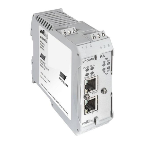
Chapter 2 - About pnGate PA EX About pnGate PA EX The pnGate PA EX is a 2-channel gateway integrating PROFIBUS PA (Process Automation) segments in PROFINET systems at a fixed speed of 31.2 kbit/s, typically used in areas of process automation with explosive atmosphere. -
Page 8: Specifications
Note Do not open the housing of the pnGate PA EX. It does not contain any parts that need to be maintained or repaired. In the event of a fault or defect, remove the device and return it to the vendor. -
Page 9: Installation
90 °C. 3.1.1 Installation in hazardous locations The pnGate PA EX may be used in hazardous locations and is certified according to ATEX. WARNING Use only according to operating conditions from instructions! Use the pnGate PA EX in accordance with its designated use only! Otherwise, the manufacturer’s liability and... - Page 10 The environmental conditions specified in the manual have to be followed strictly. § The pnGate PA EX is not to be used in systems where cathodic systems for corrosion protection are in place. Although special precautions may allow the use in such systems (additional earthing bridges), the manufacturer has to be consulted in each case.
-
Page 11: Hazardous Location - European And International Approval (Atex)
EN IEC 60079-7:2015+A1:2018 If indicated on the device label or by technical documentation, the pnGate PA EX is suitable for use in gas-Ex atmospheres of Zone 2 in the explosion groups IIA, IIB and IIC in temperature class T4, if accommodated in a tested enclosure. -
Page 12: Mounting And Dismounting
PA EX - User Guide 3.1.2 Mounting and dismounting Note Make sure the pnGate PA EX is mounted in such a way that the power supply can be easily disconnected. Note Depending on the installation position, the maximum ambient operating temperature may differ. -
Page 13: Connection Diagram
Chapter 3 - Installation 3.1.3 Connection diagram The following diagram shows the input and output interfaces of the pnGate PA EX with its 2 physical PROFIBUS segment connections (PA0 to PA1). 3.1.4 Connecting the power supply Connect the gateway to a 24 V DC power supply (not included in the delivery).The supply voltage (18 VDC .. -
Page 14: Connecting To The Network
PA EX - User Guide 3.1.5 Connecting to the network Connect each segment of your PROFIBUS network to a port of your gateway. Be sure that each segment is powered by a power conditioner. If you connect to field devices in explosive atmospheres ensure that you also connect a field barrier in between. -
Page 15: Installation Positions
Chapter 3 - Installation 3.1.6 Installation positions pnGate PA EX can be mounted horizontally and vertically. Depending on the installation position, different ambient operating temperatures (T ) are allowed. Minimum distance Provide a minimum distance of 50 mm to the air inlet and air outlet to ensure natural convection. -
Page 16: Powering Up The Device
PA EX - User Guide 3.1.7 Powering up the device Turn on the power supply. The boot process will take around 15 seconds. For indication of proper operation refer to LED status indicators Version EN-062022-1.00... -
Page 17: Software Installation
Software installation Note When you install a Softing product for the first time, you will be asked if you trust the publisher. Activate the option Always trust software from Softing AG if you do not want to be asked in subsequent installations and select [Install] to start the installation. -
Page 18: Configuration
(e.g. Siemens TIA Portal) meaning that you do not need to be connected to a controller or a gateway. The default IP address of the integrated web server is 192.168.0.10. To access the pnGate PA EX from your PC, you either have to change the default IP address of the integrated web server to an address on your network or change the DHCP address on your PC to a static IP address that matches the network address of your gateway (e.g. -
Page 19: Changing The Ip Address Of The Pngate Pa Ex
Changing the IP address of the pnGate PA EX Before you can configure the connected pnGate PA EX you will have to change the preset IP default address of your gateway so that the integrated web server can communicate with your PC over the Local Area Network. - Page 20 PA EX - User Guide Note If you are starting the connected pnGate PA EX for the first time and you have not yet assigned user roles for the gateway, the user name in the configuration window is preset to administrator.
-
Page 21: Setting The Ip Address Of The Pc
Chapter 4 - Configuration Setting the IP address of the PC If you have not changed the IP address of a pnGate PA EX as described in the previous Section will need to configure the IP address of your PC to access the gateway from your PC. -
Page 22: Login To User Interface
PA EX - User Guide Login to user interface Open your Internet browser and enter the IP address of your gateway. Note If you don't recall the IP address of your gateway, start the tool to find out what it is (see Step 2 below). -
Page 23: Changing The Password
In this case contact Softing support. Access to your pnGate PA EX configuration tool is managed by user roles where each role has certain permissions. The following user roles are available:... - Page 24 PA EX - User Guide Note It is strongly recommended to change the Diagnostics and Expert passwords immediately by entering the user name in the input field instead of selecting one of the icons above. The following table shows the permissions/actions of each user role:...
-
Page 25: Updating The Firmware
Updating the firmware The gateway comes with pre-installed firmware which is maintained and updated to continuously enhance the functionality of the device. To ensure that your pnGate PA EX is always running the most recent version check the Softing Download Center for the most recent firmware update. -
Page 26: Profinet Configuration In The Tia Portal
PA EX - User Guide PROFINET configuration in the TIA Portal The following chapter describes how to convert the GSD file of a PROFIBUS PA field device to a GSDML using the built-in PROFIBUS configurator and how to use this file to configure a PROFINET device in the Siemens TIA Portal (Totally Integrated Automation Portal). -
Page 27: Creating A New Project In Siemens Tia Portal
Chapter 4 - Configuration Select the file(s) you want to import in the File Upload window and confirm the upload to the Device Catalog of your application clicking [Open]. You can add up to 64 files for conversion.The selected file appears under Device Catalog. Click [Generic GSDML] in the side menu to generate a single GSDML file from the GSD files in the Device Catalog. - Page 28 PA EX - User Guide Double-click [Devices & Networks] to open the Network View. 10. Open the Hardware Catalog. à à à à 11. Select Other field devices PROFINET IO Gateway Softing Industrial Automation GmbH Softing Process Automation Gateways.
- Page 29 Chapter 4 - Configuration Now the gateway is assigned to the controller 18. Double-click the gateway icon to open the Device View. 19. Drag a module to a free slot. The supported submodules are shown under Submodules. 20. Click the gray device symbol and select a submodule (e.g. temperature value) from the catalog to open the corresponding Properties dialog (configure the parameters of the submodule if required - similar to PA Function Block).
- Page 30 PA EX - User Guide à à 21. Select Slave Proxy General Module parameters and set the PROFIBUS master channel to the channel to which the PROFIBUS device is connected. 22. Enter the Slave Address. If required, you can configure the parameters of a submodule in this dialog window after selecting it (corresponding to PA Function Block).
- Page 31 Example: 192.168.0.10 is the web server's default address. Use a different IP address for the PROFINET. For information on how to change the web server's address refer to Changing the IP address of the pnGate PA EX 24. Save the project and download it to the device.
-
Page 32: Updating And Uploading A Gsdml File
PA EX - User Guide 4.7.4 Updating and uploading a GSDML file If you add new PROFIBUS device to a segment in the gateway user interface you will need to update the GSDML and upload it to the PROFINET engineering tool (TIA portal) using the update feature of the TIA portal to avoid the loss of I/Q address parameter. - Page 33 Chapter 4 - Configuration Click the [Change revision] button in the Catalog information window. Select the GSDML file imported in Step 3 (check date and time string) in the new window that appears. Instantiate the new PA device module and assign the correct parameter to the new device if you imported a generic GSDML.
-
Page 34: Switching From A 2-Channel To A 4-Channel Gateway
PA EX - User Guide 4.7.5 Switching from a 2-channel to a 4-channel gateway You can switch from a 2-channel to a 4-channel gateway to support more PROFIBUS devices in your network. To do this it is recommended to use the Change Revision in the TIA portal feature. - Page 35 Chapter 4 - Configuration Remove the 2-channel FAP module (Fieldbus Access Port) from the selected gateway. The FAP module is always located in slot 1. Click the [Change revision] button in the Catalog information window. Select the GSDML file imported in Step 3 (check date and time string) in the new window that appears.
-
Page 36: Profibus Parameterization With Pactware
PA EX - User Guide PROFIBUS parameterization with PACTware The following chapter describes how to configure a PROFIBUS driver and parameterize PROFIBIUS devices in PACTware using the Device Type Manager PROFIdtm. Video See also the video PROFIBUS parameterization in PACTware. -
Page 37: Configuring The Profibus Driver
Select a pnGate PA EX. Click [Add...] and enter a symbolic node name (default value is Node0). Click [Next] and enter the IP address of the pnGate PA EX in interface name field of the next window. Select a bus segment (e.g. PA0) and click [Next]. -
Page 38: Creating A Project In Pactware
PA EX - User Guide 4.8.3 Creating a project in PACTware Start PACTware. à Right-click Host PC Add Device in the device tag column of the project view. A new window appears with the available devices. Select PROFIdtm DPV1 from the list and confirm with [OK]. -
Page 39: Profibus Parameterization With Simatic Pdm
Open a command line, click [Start], type cmd and in the command window that opens, type wmic qfe|find "3033929". The answer contains information about the time, date and Internet address of the installation. § The PDM libraries of the Softing PROFIBUS must have been downloaded from the pnGate product website and must be installed. -
Page 40: Connecting The Simatic Manager
PA EX - User Guide 4.9.3 Connecting the SIMATIC Manager This Chapter describes how you connect your pnGate PA EX with the SIMATIC Manager: à à à à Select Start All Programs Siemens Automation SIMATIC SIMATIC Manager to create a new project. - Page 41 Chapter 4 - Configuration 10. Click the [Assign Device Type...] button. The Assign Device Type window is opened. 11. Select PROFIBUS DP network in the new window. 12. Click [OK] in both windows. You are back in the Process Device Network View. à...
- Page 42 PA EX - User Guide 14. Click the Start Scan icon ( ) in the top left corner under the menu bar. This will run a network scan to verify that the PA device can be reached. The icon ( ) indicates that a device can be reached to read and write process parameters.
- Page 43 Chapter 4 - Configuration à 16. Right-click in the PROFIBUS DP network view and select Insert New Object Object. 17. Click the [Assign Device Type...] button. A new window opens. 18. Select the device you want to access from the device type list and click [OK]. 19.
- Page 44 PA EX - User Guide 22. Click the Measured Value Display icon ( ) underneath the menu bar to import the parameter values of the PA device to the Process Device Manger. Version EN-062022-1.00...
-
Page 45: Led Status Indicators
Chapter 5 - LED status indicators LED status indicators The pnGate PA EX displays eight device status LEDs and two RJ45 connection status LEDs on the front side: Device status LEDs RJ45 status LEDs power supply - refer to next section... -
Page 46: Status Leds (Pwr, Run, Err And Cfg) In Stand-Alone Mode
PA EX - User Guide Status LEDs (PWR, RUN, ERR and CFG) in stand-alone mode LEDs Meaning Start–up phase (approximately 10 seconds) Operating system starts (approximately 2 seconds) Device is running in factory mode (only firmware update is possible) -
Page 47: Profinet Device Leds (Pn)
Chapter 5 - LED status indicators PROFINET device LEDs (PN) LEDs Meaning No connection to controller Possible causes: PROFINET name is missing on the gateway or the physical connection to the gateway is interrupted. Connection establishment Time period the system needs to establish a connection; devices cannot yet communicate with each other. -
Page 48: Declaration Of Conformity
The CE marking indicates conformity with the above standards in a Declaration of Conformity which can be requested from Softing Industrial Automation GmbH. RoHS This product is compliant the Restriction of Hazardous Substances under Directive... -
Page 49: Glossary
Chapter 7 - Glossary Glossary Terms & Abbreviations Definition Direct Current - electric current flowing in only one direction Deutsches Institut für Normung Device Type Manager Decentralised Peripherals Electronic Device Description. A file created by the device manufacturer or a service provider. It is shipped together with the device on a data carrier and / or made available for download from the Internet by the manufacturer. - Page 50 Softing Industrial Automation GmbH Richard-Reitzner-Allee 6 + 49 89 45 656-340 85540 Haar / Germany + 49 89 45 656-488 https://industrial.softing.com info.idn@softing.com...
Need help?
Do you have a question about the pnGate PA EX and is the answer not in the manual?
Questions and answers