Softing smartLink HW-DP User Manual
Hide thumbs
Also See for smartLink HW-DP:
- User manual (48 pages) ,
- User manual (72 pages) ,
- User manual (90 pages)

Subscribe to Our Youtube Channel
Related Manuals for Softing smartLink HW-DP


Summary of Contents for Softing smartLink HW-DP
- Page 1 User Guide smartLink HW-DP Version: EN-042022-1.20 © Softing Industrial Automation GmbH...
- Page 2 . For deta i l s s ee https ://opens ource.s ofti ng.com/ If you a re i nteres ted i n our s ource modi fi ca ti ons a nd s ources us ed, pl ea s e conta ct: i nfo@s ofti ng.com Softing Industrial Automation GmbH Richard-Reitzner-Allee 6 85540 Haar / Germany https://industrial.softing.com...
-
Page 3: Table Of Contents
Software installation ......................20 Chapter 4 Configuration ..................21 Prerequisites ......................21 Changing the IP address of a smartLink HW-DP ......................21 Setting the IP address of your PC ......................23 Login to user interface ......................24 Configuring PROFIBUS ......................25... - Page 4 Table of Contents ......................27 Prerequisites 5.2.1 Creating a project in PACTware ......................27 5.2.2 Setting HART device parameters with PACTware ......................29 ......................29 5.3.1 Prerequisites Setting PROFIBUS device parameters with SIMATIC PDM ......................29 ......................29 Prerequisites 5.4.1 Connecting to SIMATIC PDM ......................
- Page 5 Table of Contents ......................68 Settings 6.7.1 Mapping ......................68 6.7.2 MQTT ......................69 ......................69 6.8.1 Settings ......................69 6.8.2 Chapter 7 Declaration of conformity ..................70 Chapter 8 Glossary ..................71 Version EN-042022-1.20...
- Page 6 This page is intentionally left blank. Version EN-042022-1.20...
-
Page 7: About This Guide
About this guide Read me first Please read this guide carefully before using the device to ensure safe and proper use. Softing does not assume any liability for damages due to improper installation or operation of this product. This document is not warranted to be error-free. The information contained in this document is subject to change without prior notice. -
Page 8: Document History
§ smartLink DTM User Guide § Video tutorial - Integrating and using Softing smartLink HW-DP Document feedback We would like to encourage you to provide feedback and comments to help us improve the documentation. You can write your comments and suggestions to the PDF file using the editing tool in Adobe Reader and email your feedback to support.automation@softing.com. -
Page 9: About Smartlink Hw-Dp
Intended use The smartLink HW-DP is designed to be used as a secure access point to PROFIBUS networks. Any other use is deemed non-intended use. CAUTION Do not use this device in hazardous areas! See Section... -
Page 10: System Requirements
DP, divert the electrostatic discharge away from your body and the tools used. Note Do not open the housing of the smartLink HW-DP. It does not contain any parts that need to be maintained or repaired. In the event of a fault or defect, remove the device and return it to the vendor. -
Page 11: Led Status Indicators
Chapter 2 - About smartLink HW-DP LED status indicators smartLink HW-DP has four device status LEDs and two RJ45 connection status LEDs on the front: power supply - refer to next section running - refer to next section error - refer to... -
Page 12: Status Leds Startup Phase
HW-DP - User Guide 2.7.1 Status LEDs startup phase Meaning LEDs Power Off – check Power supply. Power On - 24V DC power supply is ok. Start up phase (up to 30 seconds). Start up phase finished – check execution mode (normal or factory). -
Page 13: Status Leds - Normal Mode
Chapter 2 - About smartLink HW-DP 2.7.3 Status LEDs – normal mode Meaning LEDs Device running in Normal mode. n.a. n.a. Firmware update is running. n.a. n.a. Device joined PROFIBUS and is online. n.a. Device is configuring for PROFIBUS or Bus error. -
Page 14: Installation
3.1.1 Mounting and dismounting Note Make sure the smartLink HW-DP is mounted in such a way that the power supply can be easily disconnected. Depending on the installation position, the maximum ambient operating temperature may differ. See Section Installation positions for details. -
Page 15: Connection Diagrams
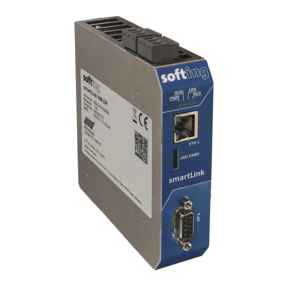
3.1.2 Connection diagrams The following diagram shows the input and output interfaces of the smartLink HW-DP. The device has one 10/100/1000 Base-T Ethernet port (ETH1) and one RS-485 link (DP 1) for PROFIBUS DP data communication. The connectors on the top are reserved for the supply voltage and alarm output. The uSD card slot is used for future service purposes and is not supported in the current version of the product. -
Page 16: Power And Alarm Connectors
HW-DP - User Guide 3.1.3 Power and alarm connectors Connect the smartLink HW-DP to a 24 V DC power supply. Note smartLink HW-DP is intended for connection to a SELV/PELV circuitry only. Power connector The supply voltage (18 VDC ..32 VDC) is connected by a 3-pole terminal block. The power supply is connected to the plug connector via flexible wires with a cross section of 0.75 to 1.5 mm². -
Page 17: Installation Positions
Chapter 3 - Installation 3.1.4 Installation positions The smartLink HW-DP can be mounted horizontally and vertically. Depending on the installation position, different ambient operating temperatures (T ) apply. Minimum distance Provide a minimum distance of 50 mm to the air inlet and air outlet to ensure natural convection. -
Page 18: Connecting To The Network
Connect your PROFIBUS network to the RS485 port of your smartLink HW-DP. Connect your PC running the engineering and asset management tools using the Ethernet port. WARNING Installing smartLink HW-DP while your network is in operation may cause data transfer problems if the network is in a poor electrical condition. 3.1.6 Powering up the device Turn on the power supply. -
Page 19: Factory Reset
Release the reset button. The two LEDs in the middle (RUN and ERR) are flashing red. When the light turn off, the smartLink HW-DP is reset and starts in factory settings. First the LED PWR turns from yellow to green, then the LED RUN turns from red to green. Now the device is operational again. -
Page 20: Software Installation
HW-DP - User Guide Software installation When you install a Softing product for the first time, you will be asked if you trust the publisher. Activate the option Always trust software from Softing AG if you do not want to be asked in subsequent installations and select [Install] to start the installation. -
Page 21: Configuration
PROFIBUS devices. The default IP address of the integrated web server is 192.168.0.10. To access the smartLink HW-DP from your PC, you either have to change the default IP address of the integrated web server to an address on your network or change the IP address on your PC network adapter to match the network address of your device (e.g. - Page 22 HW-DP - User Guide Click [Configure] or double-click the device. The configuration window opens. Here you can change the IP settings. Note You may also change the hostname. However, ensure that you follow hostname specifications RFC 952 and RFC 1123.
-
Page 23: Setting The Ip Address Of Your Pc
Chapter 4 - Configuration Setting the IP address of your PC If you have not changed the IP address of the smartLink HW-DP as described in the previous Section you will need to configure the IP address of your PC to access the gateway from your PC. -
Page 24: Login To User Interface
Search And Configure tool to find out what it is (see Step 2 below). Double-click the IP address of the smartLink HW-DP to launch the login window in your web browser. Enter administrator in the user field and the default password below, which is a combination of the part number and the serial number. -
Page 25: Configuring Profibus
Chapter 4 - Configuration Configuring PROFIBUS See Section Profibus configuration in Chapter Working with the user interface and the Video tutorial - Integrating and using Softing smartLink HW-DP for more details. Version EN-042022-1.20... -
Page 26: Asset Management
HW-DP. Preparing for asset management Installation § Install the most recent version of PROFIdtm or PDM library from the smartLink HW-DP product website. § Install the most recent version of smartLink DTM from the product website. PROFIBUS Configuration for PROFIdtm and PDM Double-click the icon to select the PROFIBUS DTM (PROFIdtm) driver. -
Page 27: Setting Profibus Device Parameters With Pactware
Chapter 5 - Asset management Setting PROFIBUS device parameters with PACTware PACTware is an FDT frame application which allows you to view field devices of different suppliers in a graphical interface similar to a browser window. To manage the information of these devices, PACTware uses a Device Type Manager (DTM) within the frame application. - Page 28 HW-DP - User Guide Note Before starting a topology scan ensure that suitable Device DTMs are installed for the connected PROFIBUS devices. Right-click PROFIdtm and select Topology Scan. Click the arrow in the scan window to start the topology scan.
-
Page 29: Setting Hart Device Parameters With Pactware
Manager (DIM). If not available, download them from the Siemens support website and import them in the DIM. § The PDM libraries of the Softing PROFIBUS must have been downloaded from the product website and must be installed. 5.4.2 Connecting to SIMATIC PDM Connecting the SIMATIC Manager with the smartLink HW-DP device: à... - Page 30 (See Section 5.1 Preparation Click [OK]. You will return to the main window (Component View). Note A logical connection has now been established between the smartLink HW-DP and the SIMATIC Manager. à Go to View Process Device Network View. Right-click on the configuration symbol in the Process Device Network View and select Insert à...
- Page 31 Chapter 5 - Asset management 12. Click [OK]. You are back in the Process Device Network View. à à 13. Right-click in the left column PROFIBUS DP network SIMATIC PDM Start LifeList. 14. Click the Start Scan icon ( ) in the top left corner under the menu bar. This will run a network scan to verify that the PROFIBUS device can be reached.
- Page 32 HW-DP - User Guide 15. Close the window in the top right corner ( à 16. Right-click in the PROFIBUS DP network view and select Insert New Object Object. 17. Click the [Assign Device Type...] button. A new window opens.
- Page 33 Chapter 5 - Asset management 20. Click [OK] to confirm. The window is closed. 21. Right-click in the Process Device Network View on the device you have just selected and select Object. This opens the SIMATIC PDM view which shows the parameter values of the selected device. 22.
-
Page 34: Connecting To Hart Ip Interfaces
HW-DP - User Guide Connecting to HART IP interfaces For details on how to connect your smartLink HW-DP over HART IP with an Asset Management System (AMS) see Sections HART IP PROFIBUS device assignment 5.5.1 Supported HART IP RIOs... -
Page 35: Using Emerson Ams
Management System. For details see also the Emerson AMS user manual. Changes to settings and values of HART device (such as names and units) connected to the network are automatically displayed in the Live List in the smartLink HW-DP user interface. 5.5.2.1 Preparations §... - Page 36 HW-DP - User Guide Wait Right-click the icon at the bottom of your screen and to start the AMS Device Manager Server again. à à Click Windows Start AMS Devices Manager Network Configuration. The AMS network configuration window opens.
- Page 37 Keep the default port 5094. 11. Click [Add Gateway]. The added gateway is shown with the corresponding IP address. 12. Click [Finish]. Your smartLink HW-DP are now shown as available network components by the name and the corresponding IP address you entered. Version EN-042022-1.20...
- Page 38 HW-DP - User Guide 13. Click [Close]. à à 14. Click Windows Start AMS Devices Manager AMS Devices Manager. The AMS device manager window opens. 15. Right-click your gateway (SmartLinkDP) and select Rebuild Hierarchy. The gateway scans the network for connected PROFIBUS RIOs. When the scan is finished, the SmartLinkDP tree topology shows all PROFIBUS RIOs as HART Cards.
- Page 39 Chapter 5 - Asset management When the scan has finished you can continue configuring the HART Devices. Follow the instructions in the Emerson AMS manual. Version EN-042022-1.20...
-
Page 40: Connecting To Opc Ua
HW-DP - User Guide Connecting to OPC UA Note For details on how to connect your smartLink HW-DP with an OPC UA Client see Sections OPC UA PROFIBUS device assignment Start the dataFEED client. Double click Double-Click to add session under Project. - Page 41 Chapter 5 - Asset management Click [OK] to close the window. You will see the established connection in the Configuration Browse window. Version EN-042022-1.20...
-
Page 42: Data Type Conversion
5.6.1 Data type conversion smartLink HW-DP converts PROFIBUS data types to OPC UA data types. Simple data types like Integer16 are mapped to the corresponding OPC UA data types (Int16). All multi-byte data types are converted from big endianness used by PROFIBUS to little endianness used by OPC UA. More complex, structured data types are split up to multiple OPC UA variables. - Page 43 Chapter 5 - Asset management PROFIBUS data type OPC UA variable OPC UA data type conversion name suffix Unsigned8+Unsigned8 _value Byte _status Byte OctetString2+Unsigned8 _value ByteString _status Byte Unsigned16_S _value UInt16 big -> little endian Input >> 2 (zero-padding shift) _status Byte Input &...
-
Page 44: Address Spaces
HW-DP - User Guide Address spaces To use the protocols above, PROFIBUS address spaces have to be defined for each one. Due to the unique nature of each protocol simultaneous read and write requests to the devices can inflict each other. It is therefore not recommended to use more than one protocol in each address space. -
Page 45: Working With The User Interface
Chapter 6 - Working with the user interface Working with the user interface See Section Log in to user interface for details on how to access the interface. General functions All interface windows display the following functions: Restart Device This function is available only when logged in as administrator or maintenance engineer and is used to restart the gateway remotely as instructed in this user guide or whenever required in ongoing operation. -
Page 46: License
This is the ID you will need to request a licence. 6.2.2 License à Select Information License to view the licenses used by the gateway firmware under an open source license. 6.2.3 About à Select Information About to show information about Softing and other useful information. Version EN-042022-1.20... -
Page 47: Settings
Chapter 6 - Working with the user interface Settings 6.3.1 Network à Select Settings Network to view and change the TCP/IP settings. Note You need to be logged in as Administrator or Maintenance user to change default settings. If you change the settings you must restart the gateway. Parameter Meaning Obtain IP address from a DHCP... -
Page 48: User Accounts
HW-DP - User Guide 6.3.2 User accounts In this section you will learn how to change accounts and passwords. à 1. Select Settings User Accounts. As administrator you can create and delete user accounts and also change passwords. 2. Select a user role in the dropdown menu, assign a user name and enter a New password in the corresponding fields according to the password rules. - Page 49 Note The user role Diagnostic is not required for daily operations. It is reserved for internal purposes such as troubleshooting. Softing Support may ask you to add a user with this role to obtain more details of your smartLink HW-DP.
-
Page 50: Firmware Update
The gateway comes with pre-installed firmware (factory version) which is maintained and updated to continuously enhance the functionality of the device. To ensure that your smartLink HW-DP is running the latest firmware version check for the latest version in the Softing Download Center. - Page 51 Chapter 6 - Working with the user interface The system performs a firmware file check. The download starts automatically. When the download is completed the smartLink HW-DP will be rebooted. When the boot process is completed, the RUN LED is ON.
-
Page 52: Reset
Reset Unlike the factory reset (hard reset) described in Chapter Hardware Installation, this soft reset deletes the configuration of your smartLink HW-DP and restores the factory settings of your gateway. à Select Settings Reset in the side bar navigation Select [Erase Configuration] to reset your device to default settings. -
Page 53: Https
HTTP connection is used. Click on the icon to find out which type of security and certificate is used. smartLink HW-DP uses Open SSL V1.0.2 for TLS 1.2 with a self-signed Softing certificate. If you want à... - Page 54 If you change the settings you must restart the gateway. Note If you are experiencing problems with certificates, please update your web browser first with the most recent version before contacting Softing support. Note As your web browser might use cached data, please refresh the browser after rebooting the gateway.
-
Page 55: Time & Date
Chapter 6 - Working with the user interface 6.3.6 Time & Date à Select Settings Time & Date in the side bar navigation to set the time and date of your smartLink HW-DP. Click [Set time from browser] to synchronize the gateway with the PC date and time manually. Click [Use time server] and enter the IP address of your time server to synchronize date and time automatically. -
Page 56: Licensing
PROFIBUS network. A license is a unique key tied to the serial number of your gateway. It cannot be migrated or run on another smartLink HW-DP. If your smartLink HW-DP has no license or you wish to connect to more HART devices than you have previously licensed, please contact Softing Support. - Page 57 Chapter 6 - Working with the user interface How to install a license Licenses for HART Device Support are needed by any Asset Management Tool to parameterize and/or monitor HART devices. Licenses for PROFIBUS Slave Support are needed by any PROFIBUS Asset Management Tool to parameterize and/or monitor PROFIBUS slaves.
- Page 58 HW-DP - User Guide Parameter Meaning Version A support number (for internal use only). Options Total number of supported HART devices. End Date The date on which the license expires. Generally all licenses are unlimited. Description Before a license is installed, this field displays the order number for a license for this specific gateway.
-
Page 59: Diagnosis
Chapter 6 - Working with the user interface Diagnosis Note The menu Diagnosis including all submenus Settings, Log File, Threads, Status, Live List is reserved for Softing Support to help Expert users analyse system data. 6.4.1 Settings à Select Diagnosis Settings to view gateway settings and log file values. -
Page 60: Log File
Use the button [Support Data] to save all PROFIBUS and HART IP connection status data and mapping data to a file. The information contained in this file may provide Softing Support with valuable information to address and fix potential issues. -
Page 61: Threads
à Select Diagnosis Threads to view the current state of the threads. The list you will see and the details contained may not be of any use to you but helps Softing support to diagnose device and performance errors. 6.4.4 Status à... -
Page 62: Live List
Select Diagnosis Live List to see a list of all connected HART devices. After smartLink HW-DP has finished booting, it starts scanning the PROFIBUS network for Remote IOs (RIOs) and displays a list with all active (live) HART devices. The number of connected HART devices and corresponding licenses are is shown at the top of the window. -
Page 63: Profibus
Chapter 6 - Working with the user interface PROFIBUS 6.5.1 Configuration This section describes how to configure the PROFIBUS bus parameters of the smartLink HW-DP. You need to be logged in as Administrator or Maintenance User. à Select PROFIBUS Configuration. - Page 64 HW-DP - User Guide Click [Apply Configuration] in the side menu Meaning Actions Import GSD Import GSD device description file to device catalog. Remove all GSDs Deletes all previously imported GSDs. Clear Configuration Deletes all configured devices. Load Configuration Loads a previously saved configuration.
-
Page 65: Device Assignment
The PROFIBUS network can be accessed through multiple clients in parallel. As any parallel access of the same slave may create an undefined state, each Ethernet interface of smartLink HW-DP can be configured with a designated PROFIBUS device address range. So clients connecting to the network via smartLink HW-DP only see devices which are assigned to the interface they are using. -
Page 66: Log
HW-DP - User Guide 6.5.3 The PROFIBUS log represents the state of the PROFIBUS connection. The data helps Softing Support troubleshoot a connection problem. Click [Refresh] to update the PROFIBUS log. HART IP 6.6.1 Settings à Select HART IP Settings to see the current settings. -
Page 67: Log
Chapter 6 - Working with the user interface 6.6.2 à Select HART IP Log to see details of the HART IP communication activity. This log file is typically used by Softing support for troubleshooting a problem. Version EN-042022-1.20... -
Page 68: Opc Ua
HW-DP - User Guide OPC UA If you want to connect to PROFIBUS DP devices using OPC UA communication make sure you have installed the GSDs of the field devices and configured the field devices. 6.7.1 Settings à Select OPC UA Settings to see the current settings. -
Page 69: Mqtt
MQTT is a lightweight, publish-subscribe network protocol that transports messages between devices, suitable for transmitting data to the cloud. smartLink HW-DP uses MQTT to sends asset and diagnostics data of PROFIBUS devices. You can connect arbitrary MQTT client applications to process this information. -
Page 70: Declaration Of Conformity
The CE marking indicates conformity with the above standards in a Declaration of Conformity which can be requested from Softing Industrial Automation GmbH. RoHS This product is compliant the Restriction of Hazardous Substances under Directive 2002/95/EC. -
Page 71: Chapter 8 Glossary
Chapter 8 - Glossary Glossary Terms & Definition Abbreviations DHCP Dynamic Host Configuration Protocol Deutsches Institut für Normung Device Type Manager Decentralised Peripherals Ethernet Explosion protection Field Device Tool Ground General Station Description (a file containing the manufacturer's device data base) HART Highway Addressable Remote Transducer HTTPS... - Page 72 Softing Industrial Automation GmbH Richard-Reitzner-Allee 6 + 49 89 45 656-340 85540 Haar / Germany + 49 89 45 656-488 https://industrial.softing.com info.idn@softing.com...
Need help?
Do you have a question about the smartLink HW-DP and is the answer not in the manual?
Questions and answers