
Related Manuals for Softing epGate PA


Summary of Contents for Softing epGate PA
- Page 1 User Guide EtherNet/IP Gateways Version: EN-062020-1.00 © Softing Industrial Automation GmbH...
- Page 2 The information contained in these instructions corresponds to the technical status at the time of printing of it and is passed on with the best of our knowledge. Softing does not warrant that this document is error free. The information in these instructions is in no event a basis for warranty claims or contractual agreements concerning the described products, and may especially not be deemed as warranty concerning the quality and durability pursuant to Sec.
-
Page 3: Table Of Contents
Table of Contents Table of Contents About this guide ..................5 Chapter 1 Read me first ....................... 5 Target audience ....................... 5 Typographic conventions ....................... 5 Document history ....................... 6 Related documentation and videos ....................... 6 Document feedback ....................... 6 About the EtherNet/IP Gateways .................. - Page 4 Table of Contents ......................28 Prerequisites 6.2.1 ......................28 Creating a project in PACTware 6.2.2 Setting device parameters with SIMATIC PDM ....................... 30 ......................30 Prerequisites 6.3.1 ......................30 Connecting to SIMATIC PDM 6.3.2 LED status indicators ..................34 Chapter 7 Status LEDs (PWR, RUN, ERR and CFG) .......................
-
Page 5: About This Guide
About this guide Read me first Please read this guide carefully before using the device to ensure safe and proper use. Softing does not assume any liability for damages due to improper installation or operation of this product. This document is not warranted to be error-free. The information contained in this document is subject to change without prior notice. -
Page 6: Document History
You can write your comments and suggestions to the PDF file using the editing tool in Adobe Reader and email your feedback to support.automation@softing.com. If you prefer to write your feedback directly as an email, please include the following information with... -
Page 7: About The Ethernet/Ip Gateways
PROFIBUS master for easy connection of PROFIBUS network slave devices to an EtherNet/IP control system. The epGate PA is available as a 2-channel model and a 4-channel model. Both models integrate PROFIBUS PA (Process Automation) networks in EtherNet/IP systems at a fixed speed of 31.25 kbit/s. -
Page 8: Supported Features
EtherNet/IP Gateways - User Guide Supported features The EtherNet/IP Gateway supports the following features: Simple connection to PROFIBUS PA and PROFIBUS DP slaves Integration in FDT frame applications Configuration of the gateway in a web browser Integrated configurator to start up the PROFIBUS slaves Access to process values of PROFIBUS slaves (input and output) in the Ethernet/IP control program Read access to status information of the PROFIBUS slaves in the Ethernet/IP control program Changing of operation state of the PROFIBUS master (STOP/RUN) in the Ethernet/IP control program... -
Page 9: Installation
Chapter 3 - Installation Installation Hardware installation Note With an ambient temperature above 55 °C at the place of installation it is very likely that the temperatures of connecting cables will increase if the cables are installed in an unfavourable position. -
Page 10: Connection Diagrams Pa Model
3.1.2 Connection diagrams PA Model The epGate PA is available as a 2-channel model and a 4-channel model. The 2-channel model has 2 physical PROFIBUS segment connections (PA0 to PA1) while the 4-channel model has 4 physical PROFIBUS segment connections (PA0 to PA3). -
Page 11: Connection Diagram Pb Model
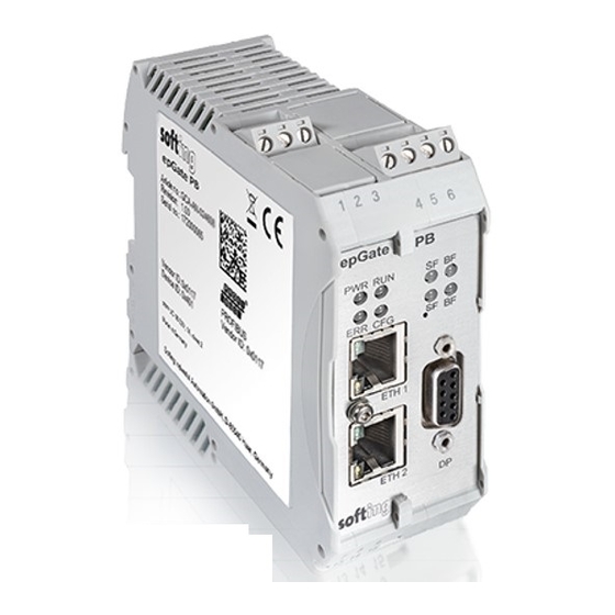
Chapter 3 - Installation 3.1.3 Connection diagram PB Model The epGate PB has two physical PROFIBUS PA segment connections (PA0 to PA1) and one RS-485 connection (DP). The gateway has two 10/100 Base-T Ethernet ports (ETH1/ETH2). Both RJ45 ports correspond to IEEE802.3 and are connected to an internal switch for line topologies. The following diagram shows the side profile of the epGate PB model with the input and output interfaces and fieldbus connections: 3.1.4... -
Page 12: Connecting The Power Supply
Connecting the power supply Note As the epGate PA and epGate PB does not supply power to the PROFIBUS PA connections, each PA segment of your PROFIBUS network requires its own power supply with power conditioning (such as power conditioner R.STAHL 9412). -
Page 13: Installation Positions
Chapter 3 - Installation 3.1.6 Installation positions The EtherNet/IP Gateway can be mounted horizontally and vertically. Depending on the installation position, different ambient operating temperatures (T ) are allowed. Minimum distance Provide a minimum distance of 50 mm to the air inlet and air outlet to ensure natural convection. - Page 14 EtherNet/IP Gateways - User Guide Number of PA Maximum PA fieldbus Minimum distance Maximum ambient channels used voltage temperature T 0 - 4 32VDC 0 mm 40 °C 0 - 2* 24VDC 0 mm 45 °C 0 - 4 32VDC 17.5 mm 50 °C 0 - 2*...
-
Page 15: Connecting To The Network
2. Connect the gateway from one of the two Ethernet ports with your EtherNet/IP network. 3. Connect your PC running the engineering and asset management tools using the second Ethernet port. epGate PA (2-channel model) Version EN-062020-1.00... -
Page 16: Powering Up The Device
EtherNet/IP Gateways - User Guide epGate PB epGate DP 3.1.8 Powering up the device Turn on the power supply. The boot process will take around 15 seconds. For indication of proper operation refer to LED status indicators Version EN-062020-1.00... -
Page 17: Software Installation
Software installation Note When you install a Softing product for the first time, you will be asked if you trust the publisher. Activate the option Always trust software from Softing AG if you do not want to be asked in subsequent installations and select [Install] to start the installation. -
Page 18: Configuration
PC can communicate with the integrated web server over the Local Area Network. The following steps apply to Windows 10. 1. Click Start Softing Search and Configure. The application window is opened. 2. Click the dropdown list of the Network Adapter Selection. - Page 19 Chapter 4 - Configuration 5. Select the gateway you want to configure. 6. Click [Configure] or double-click the device. The configuration window opens. Here you can change the IP settings. Note You may also change the hostname. However, ensure that you follow hostname specifications RFC 952 and RFC 1123.
-
Page 20: Setting The Ip Address Of Your Pc
EtherNet/IP Gateways - User Guide Setting the IP address of your PC If you have not changed the IP address of the EtherNet/IP Gateway as described in the previous Section you will need to configure the IP address of your PC to access the gateway from your PC. The following chapter describes how to set a static IP address in Windows 10. -
Page 21: Login To User Interface
Chapter 4 - Configuration Login to user interface 1. Open your Internet browser and enter the IP address of your gateway. Note If you can't recall the IP address of your gateway, start the Search And Configure tool to find out what it is (see Step 2 below). 2. -
Page 22: Configuring Ethernet/Ip
Note As all three gateways have the same PROFIBUS master interface, the configuration instructions for epGate PA also apply to epGate PB and epGate DP. Video Watch the video PROFIBUS configuration to find out how to configure the PROFIBUS master interface of your gateway. -
Page 23: Connection To A Controller
Chapter 5 - Connection to a controller Connection to a controller The following chapter describes how to establish a EtherNet/IP connection using the engineering systems Rockwell Studio 5000 or Emerson DeltaV. EtherNet/IP Mapping The EtherNet/IP Gateway maps the I/O data and statuses of the configured PROFIBUS slaves to EtherNet/ IP input and output assemblies. - Page 24 EtherNet/IP Gateways - User Guide The following table explains the columns of the EtherNet/IP mapping shown above. Parameter Meaning Name of the field Field Name Data type of the field Field type Byte offset in the assembly Offset Device type name as stated in the GSD file Device Name Name specified in the PROFIBUS configuration web page Device Tag...
- Page 25 Chapter 5 - Connection to a controller DeviceStatus The field DeviceStatus is a byte array containing the status of all configured PROFIBUS slaves in all segments. Each byte represents the status of one slave. The order of the PROFIBUS slaves in the byte array is analog to the field DeviceFailure.
-
Page 26: Asset Management
The configuration wizard is closed. In the Control Panel the node name is shown on the left side underneath epGate PA/DP/PB. The question mark on a yellow background means that the connection to the EtherNet/IP Gateway has not yet been tested. - Page 27 Chapter 6 - Asset Management 13. Click [Apply] in the PROFIBUS Control Panel to save all settings and confirm with [Yes]. The PROFIBUS Control Panel tests the connection to the EtherNet/IP Gateway. After a short while, the yellow question mark is replaced by a green check mark. If a red cross appears instead, check the network cables and the IP settings of your PC and the gateway.
-
Page 28: Setting Device Parameters With Pactware
The answer contains information about the time, date and Internet address of the installation. Hint If you have downloaded PACTware from the product website, Softing PROFIdtm is included and automatically installed, unless you actively uncheck the option to install Softing PROFIdtm at this time. - Page 29 Chapter 6 - Asset Management Note Before starting a topology scan ensure that suitable Device DTMs are installed for the connected PROFIBUS devices. 5. Right-click PROFIdtm and select Topology Scan. 6. Click the arrow in the scan window to start the topology scan. PROFIdtm and the detected PROFIBUS devices are displayed in the scan window.
-
Page 30: Setting Device Parameters With Simatic Pdm
EDD files and libraries of the PA devices must be imported in the PDM Device Integration Manager. If not available, download them from the Siemens support website and import them in the DIM. The PDM libraries of the Softing PROFIBUS must have been downloaded from the epGate product website and must be installed. - Page 31 Chapter 6 - Asset Management 8. Right-click on the configuration symbol in the Process Device Network View and select Insert New Object networks. 9. Right-click on the network symbol and select Insert New Object Communication network. 10. Click the [Assign Device Type...] button. The Assign Device Type window is opened.
- Page 32 EtherNet/IP Gateways - User Guide 14. Click the Start Scan icon ( ) in the top left corner under the menu bar. This will run a network scan to verify that the PA device can be reached. The icon ( ) indicates that a device can be reached to read and write process parameters. 15.
- Page 33 Chapter 6 - Asset Management 18. Select the device you want to access from the device type list and click [OK]. 19. Enter the PROFIBUS address. 20. Click [OK] to confirm. The window is closed. 21. Right-click in the Process Device Network View on the device you have just selected and select Object. This opens the SIMATIC PDM view which shows the parameter values of the selected device.
-
Page 34: Led Status Indicators
EtherNet/IP Gateways - User Guide LED status indicators The EtherNet/IP Gateway displays eight device status LEDs and two RJ45 connection status LEDs on the front side: Device status LEDs RJ45 status LEDs = Power supply - refer to next section = Running - refer to next section = Error - refer to... -
Page 35: Status Leds (Pwr, Run, Err And Cfg)
Chapter 7 - LED status indicators Status LEDs (PWR, RUN, ERR and CFG) Meaning LEDs Start-up phase (approximately 10 seconds) 24V DC power supply is ok. Operating system starts (approximately 2 seconds) Device is running in factory mode (only firmware update is possible) Device is running/operational Software error A software error occurred. -
Page 36: Ethernet/Ip Leds
EtherNet/IP Gateways - User Guide EtherNet/IP LEDs Network status (Net) LEDs Meaning Not powered, no IP address, no Ethernet link The device is powered off, or is powered on with no IP address configured No connections An IP address is configured, but no CIP connection is established Connected An IP address is configured, at least one CIP connection is established Connection timeout... -
Page 37: Profibus Leds
Chapter 7 - LED status indicators PROFIBUS LEDs LEDs Meaning All channels offline All devices exchange data on all channels At least one used channel is not online At least one slave is not in data exchange BF: green - all channels are online; red: not all channels are online. Error in the PROFIBUS part of the device An error such as a software error or a license error has occurred. -
Page 38: Using The Web Interface
EtherNet/IP Gateways - User Guide Using the web interface General functions All interface windows display the following three functions: Restart Device This function is available only when logged in as administrator or maintenance engineer and is used to restart the gateway remotely as instructed in this user guide or whenever required in ongoing operation. Logout Select this function to log out as an active user. -
Page 39: System
(not available with current firmware version) 8.2.2 License Select Information License to view the licenses used by the gateway firmware under an open source license. 8.2.3 About Select Information About to show information about Softing and other useful information. Version EN-062020-1.00... -
Page 40: Settings
EtherNet/IP Gateways - User Guide Settings 8.3.1 Network Select Settings Network to view and change the TCP/IP settings. Note You need to be logged in as administrator or config to change default settings. If you change the settings you must restart the gateway. Parameter Meaning Obtain IP address from a DHCP... -
Page 41: User Accounts
FS-QsHnc7BWa{6w<). Both user roles are reserved strictly for <fJ#\/$eB2qtGd*) Softing Support purposes. Note It is strongly recommended to change the Diagnostics and Expert passwords immediately by entering the user name in the input field instead of selecting one of the icons above. - Page 42 EtherNet/IP Gateways - User Guide The following table shows the permissions of each user role: Permission Administrator Service Engineer Observer Setting password Configuring gateway Reading configuration Reading diagnostics Updating firmware Resetting gateway Installing HTTPS certificates Version EN-062020-1.00...
-
Page 43: Firmware Update
The gateway comes with pre-installed firmware which is maintained and updated to continuously enhance the functionality of the device. To ensure that your EtherNet/IP Gateway is running the latest firmware version check for the latest version in the Softing Download Center. - Page 44 EtherNet/IP Gateways - User Guide The system performs a firmware file check. The download starts automatically. When the download is completed the EtherNet/IP Gateway will be rebooted. When the boot process is completed, the RUN LED is ON. Note After the gateway has rebooted you are automatically forwarded to the log in page. If this fails please reload the web page.
-
Page 45: Reset
HTTP connection is used. Click on the icon to find out which type of security and certificate is used. All three gateways use Open SSL V1.0.2 for TLS 1.2 with a self-signed Softing certificate. If you want to use a different certificate to secure your gateway, select Settings HTTPS and choose the upload options to install a private key, server certificate file and intermediate certificate files. - Page 46 If you change the settings you must restart the gateway. Note If you are experiencing problems with certificates, please update your web browser first with the most recent version before contacting Softing support. Note As your web browser might use cached data, please refresh the browser after rebooting the gateway.
-
Page 47: Diagnosis
Settings to view gateway settings and log file values. The settings can be viewed in any role. To change the settings you must have administration rights. Note The menu Diagnosis including all submenus Settings, Log File, Threads, Status is reserved for Softing Support to help Expert users analyse system data. 8.4.1 Settings Select Diagnosis Settings to view gateway settings and change your log file priority. -
Page 48: Logfile
EtherNet/IP Gateways - User Guide 8.4.2 Logfile Select Diagnosis Logfile to view the log file entries. You can also filter the diagnostic log by ticking and unticking the checkboxes of the different priorities. This only affects the display of the log and not the setting of the log file priority under Diagnosis Settings. -
Page 49: Threads
8.4.3 Threads Select Diagnosis Threads to view currently running threads. The list you will see and the details contained may not be of any use to you but helps Softing support to diagnose device and performance errors. 8.4.4 Status Select Diagnosis Status to view gateway diagnostics. -
Page 50: Ethernet/Ip
EtherNet/IP Gateways - User Guide EtherNet/IP 8.5.1 Settings To change the EtherNet/IP settings you need to be logged in as administrator Select EthernetIP Settings and follow the instructions in the section Configuring EtherNet/IP Parameter Meaning Obtain IP settings EtherNet/IP If the checkbox is selected, the IP settings for access are from a DHCP server obtained from DHCP server. -
Page 51: Mapping
Chapter 8 - Using the web interface 8.5.2 Mapping The EtherNet/IP mapping table displays the mapping of PROFIBUS IOs to EtherNet/IP (EIP). 8.5.3 The EtherNet/IP log represents the state of the EtherNet/IP connection. The data helps Softing Support to troubleshoot a connection problem. Version EN-062020-1.00... -
Page 52: Profibus
EtherNet/IP Gateways - User Guide PROFIBUS 8.6.1 Configuration This section describes how to configure the gateway segments PA and DP for PROFIBUS communication. You need to be logged in as administrator or config to configure the gateway. Actions Meaning Import GSD Import GSD device description file to device catalog. -
Page 53: Log
Setup Time: This is the time that may pass between receiving a data telegram and the respective reaction within a device. Max Retry Limit The total number of retries. 8.6.2 The PROFIBUS log represents the state of the PROFIBUS connection. The data helps Softing Support to troubleshoot a connection problem. Version EN-062020-1.00... -
Page 54: Declaration Of Conformity
The CE marking indicates conformity with the above standards in a Declaration of Conformity which can be requested from Softing Industrial Automation GmbH. RoHS This product is compliant the Restriction of Hazardous Substances under Directive 2002/95/ This equipment has been tested and found to comply with the limits for a Class A digital device, under part 15 of the FCC Rules. -
Page 55: Glossary
Chapter 10 - Glossary Glossary Terms & Definition Abbreviations Conformité Européenne" (French for "European Conformity") Direct Current - electric current flowing in only one direction Deutsches Institut für Normung Device Type Manager Decentralised Peripherals Electronic Device Description. A file created by the device manufacturer or a service provider. - Page 56 Softing Industrial Automation GmbH Richard-Reitzner-Allee 6 + 49 89 45 656-340 85540 Haar / Germany + 49 89 45 656-488 https://industrial.softing.com info.idn@softing.com...
Need help?
Do you have a question about the epGate PA and is the answer not in the manual?
Questions and answers