
Related Manuals for Kontron MITX-CFL0 Series


Summary of Contents for Kontron MITX-CFL0 Series
- Page 1 USER GUIDE MITX-CFL0 Series Doc. User Guide, Rev. 1.1 Doc. ID: [To be Determined] www.kontron.com...
- Page 2 MITX-CFL0 Series - User Guide, Rev. 1.1 This page has been intentionally left blank www.kontron.com // 2...
- Page 3 In cases of doubt, please contact Kontron. This user guide is protected by copyright. All rights are reserved by Kontron. No part of this document may be reproduced, transmitted, transcribed, stored in a retrieval system, or translated into any language or computer language, in any form or by any means (electronic, mechanical, photocopying, recording, or otherwise), without the express written permission of Kontron.
- Page 4 ENVIRONMENTAL DAMAGE (COLLECTIVELY, "HIGH RISK APPLICATIONS"). You understand and agree that your use of Kontron devices as a component in High Risk Applications is entirely at your risk. To minimize the risks associated with your products and applications, you should provide adequate design and operating safeguards.
- Page 5 If you have any difficulties using this user guide, discover an error, or just want to provide some feedback, contact Kontron support. Detail any errors you find. We will correct the errors or problems as soon as possible and post the revised user guide on our website.
-
Page 6: Symbols
MITX-CFL0 Series - User Guide, Rev. 1.1 Symbols The following symbols may be used in this user guide DANGER indicates a hazardous situation which, if not avoided, will result in death or serious injury. WARNING indicates a hazardous situation which, if not avoided, could result in death or serious injury. -
Page 7: For Your Safety
Therefore, in the interest of your own safety and of the correct operation of your new Kontron product, you are requested to conform with the following guidelines. -
Page 8: Lithium Battery Precautions
General Instructions on Usage In order to maintain Kontron’s product warranty, this product must not be altered or modified in any way. Changes or modifications to the product, that are not explicitly approved by Kontron and described in this user guide or received from Kontron Support as a special handling instruction, will void your warranty. -
Page 9: Table Of Contents
MITX-CFL0 Series - User Guide, Rev. 1.1 Table of Contents Symbols .......................................... 6 For Your Safety ......................................7 High Voltage Safety Instructions ..................................7 Special Handling and Unpacking Instruction ..............................7 Lithium Battery Precautions ....................................8 General Instructions on Usage ................................8 Quality and Environmental Management ............................ -
Page 10: List Of Tables
MITX-CFL0 Series - User Guide, Rev. 1.1 7.4. USB Connectors (Internal) (F_USB1 & F_USB2) ..........................40 7.5. Speaker Connector (SPKR_R & SPKR_L) ............................... 40 7.6. Front Panel Audio Pin Header (F_AUDIO) ............................. 41 7.7. Front Panel Pin Header (F_PANEL1 & F_PANEL2) ..........................42 7.8. -
Page 11: List Of Figures
Table 49: Main Setup Menu Sub-Screens and Functions ........................72 Table 50: List of Acronyms ....................................103 List of Figures Figure 1: System Block Diagram MITX-CFL0 Series ..........................17 Figure 2: Top Side ........................................23 Figure 3: Bottom Side ......................................25 Figure 4: Connector Panel Side .................................. - Page 12 MITX-CFL0 Series - User Guide, Rev. 1.1 Figure 16: RTC Power Input Wafer BAT ................................. 38 Figure 17: Fan Wafer CPU_FAN, SYS_FAN ..............................38 Figure 18: SATA 3.0 Connector SATA3_0, SATA3_1, SATA3_2, SATA3_3 ..................39 Figure 19: USB 2.0 Port Pin Header F_USB1, F_USB2 ..........................40 Figure 20: 3W Audio AMP Output Wafer SPKR_R (Right Channel), SPKR_L (Left Channel) .............
-
Page 13: 1/ Introduction
MITX-CFL0 Series - User Guide, Rev. 1.1 1/ Introduction This user guide describe the MITX-CFL0 Series board made by Kontron. This board will also be denoted MITX-CFL0 Series within this user guide. Use of this user guide implies a basic knowledge of PC-AT hardware and software. This user guide focuses on describing the MITX-CFL0 Series board's special features and is not intended to be a standard PC-AT textbook. -
Page 14: 2/ Installation Procedures
Handle the board only by the edges To get the board running follow these steps. If the board shipped from Kontron already has components like RAM and CPU cooler mounted, then skip the relevant steps below. 1. Turn off the PSU (Power Supply Unit) Turn off PSU (Power Supply Unit) completely (no mains power connected to the PSU) or leave the Power Connectors unconnected while configuring the board. -
Page 15: Chassis Safety Standards
Do not use washers with teeth, as they can damage the PCB and cause short circuits. 2.2. Chassis Safety Standards Before installing the MITX-CFL0 Series in the chassis, users must evaluate the end product to ensure compliance with the requirements of the IEC60950-1 safety standard: ... - Page 16 MITX-CFL0 Series - User Guide, Rev. 1.1 Disponga las baterías usadas según las instrucciones del fabricante ADVARSEL! Lithiumbatteri - - Eksplosionsfare ved fejlagtig håndtering. Udskiftning må kun ske med batteri af samme fabrikat og type Levér det brugte batteri tilbage til leverandøren ADVARSEL! Eksplosjonsfare ved feilaktig skifte av batteri.
-
Page 17: 3/ System Specifications
MITX-CFL0 Series - User Guide, Rev. 1.1 3/ System Specifications 3.1. System Block Diagram Figure 1: System Block Diagram MITX-CFL0 Series www.kontron.com // 17... -
Page 18: Scope Of Delivery
MITX-CFL0 Series - User Guide, Rev. 1.1 3.2. Scope of Delivery The table below summarizes the features of the MITX-CFL0 Series motherboard. Table 1: Component Main Data System Processor 9th Generation Intel® Core™ S-Series (LGA1151 socket, up to 65 W TDP) ... -
Page 19: Environmental Conditions
Mini-ITX (170 mm x 170 mm / 6.70" x 6.70") 3.3. Environmental Conditions The MITX-CFL0 Series is compliant with the following environmental conditions. It is the customer's responsibility to provide sufficient airflow around each of the components to keep them within the allowed temperature range. -
Page 20: Processor Support
FCC Class A 3.5. Processor Support The MITX-CFL0 Series is designed to support the following processors which are connected to a discrete Intel® Q370 or H310 Chipset Platform Controller Hub on the motherboard. 9th Generation Intel® Core™ S-Series (FCLGA1151 socket, up to 65 W TDP) ... -
Page 21: On-Board Graphics Subsystem
Memory modules have in general a much lower longevity than embedded motherboards, and therefore EOL of modules can be expected several times during lifetime of the motherboard. As a minimum it is recommend using Kontron memory modules for prototype system(s) in order to prove stability of the system and as for reference. -
Page 22: Table 6: Supply Voltages
MITX-CFL0 Series - User Guide, Rev. 1.1 Table 6: Supply Voltages Supply Min. Max. Note +3.3 V 3.135 V 3.265 V Should be ±5 % for compliance with the ATX specification +5 V 4.75 V 5.25 V Should be ±5 % for compliance with the ATX specification. -
Page 23: 4/ Connector Locations
MITX-CFL0 Series - User Guide, Rev. 1.1 4/ Connector Locations 4.1. Top Side Figure 2: Top Side 24 23 21 20 Table 7: Jumper List Item Designation Description See Chapter AT_ATX AT / ATX Power Mode Selection 7.21.1 PEG_X16_X8 PCIe Configuration Setting for PCIEX16 7.21.2... -
Page 24: Table 8: Top Side Internal Connector Pin Assignment
MITX-CFL0 Series - User Guide, Rev. 1.1 Item Designation Description See Chapter BL_EN Backlight Power Enable Selection for LVDS 7.21.5 CLR_CMOS Clear CMOS Selection 7.21.6 Table 8: Top Side Internal Connector Pin Assignment Item Designation Description See Chapter ATX_12V 2x2-pin ATX Power Supply Wafer 7.1.2... -
Page 25: Bottom Side
MITX-CFL0 Series - User Guide, Rev. 1.1 4.2. Bottom Side Figure 3: Bottom Side Table 9: Bottom Side Internal Connector Pin Assignment Item Designation Description See Chapter M.2 Key M Socket 7.14 www.kontron.com // 25... -
Page 26: Connector Panel Side
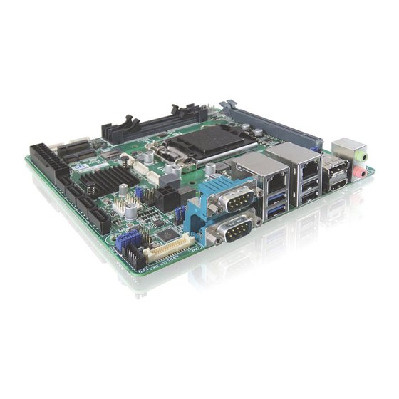
MITX-CFL0 Series - User Guide, Rev. 1.1 4.3. Connector Panel Side Figure 4: Connector Panel Side Table 10: Connector Panel Side Connector List Item Designation Description See Chapter DP_HDMI DP++ & HDMI 2.0 Connector 6.1 & 6.2 USB30_LANA GbE LAN A & USB 3.0 Port-0, 1 Connector 6.3 &... -
Page 27: 5/ Connector Definitions
MITX-CFL0 Series - User Guide, Rev. 1.1 5/ Connector Definitions The following defined terms are used within this user guide to give more information concerning the pin assignment and to describe the connector's signals. Defined Term Description Shows the pin numbers in the connector... -
Page 28: 6/ I/O-Area Connectors
MITX-CFL0 Series - User Guide, Rev. 1.1 6/ I/O-Area Connectors 6.1. DP++ Connector (DP_HDMI Top) The DP++ (Dual-mode DisplayPort) connector is based on standard DP female port. The port allows users to use a passive adapter to convert DP signals to single-link DVI or HDMI. -
Page 29: Hdmi Connector (Dp_Hdmi Bottom)
MITX-CFL0 Series - User Guide, Rev. 1.1 6.2. HDMI Connector (DP_HDMI Bottom) The HDMI connector is based on standard HDMI type A and compliant with HDMI 2.0. Figure 6: HDMI Connector DP_HDMI Bottom Table 12: Pin Assignment HDMI Connector DP_HDMI Bottom... -
Page 30: Ethernet Connectors (Usb30_Lana Lan A & Usb_Lanb Lan B)
6.3. Ethernet Connectors (USB30_LANA LAN A & USB_LANB LAN B) The MITX-CFL0 Series supports two channels of 10/100/1000 Mbit Ethernet, which are based Intel® I211-AT and Intel® I219-LM (model with Q370 chipset) / Intel® I219-LM (model with H310 chipset) controllers. -
Page 31: Usb Connectors (I/O Area)
MITX-CFL0 Series - User Guide, Rev. 1.1 6.4. USB Connectors (I/O Area) The external I/O connector panel supports two USB 2.0 connectors and two USB 3.0 connectors. USB 3.0 ports are backward compatible with USB 2.0. Figure 8: USB 2.0 Connectors USB_LANB USB 2.0 Port 2 / 3 Table 14: Pin Assignment USB 2.0 Connectors USB_LANB USB 2.0 Port 2 / 3... -
Page 32: Figure 10: Usb 2.0 High Speed Cable
MITX-CFL0 Series - User Guide, Rev. 1.1 Figure 10: USB 2.0 High Speed Cable Polyviny Chloride (PVC) Jacket On-Twisted Power Pair: Red: V Black: Power Ground Twisted Signaling Pair: Inner Shield Aluminum White: D- Green: D+ Metallized Polyester Outer Shield ≥ 65% Interwoven... -
Page 33: Serial Com 5 & Com 6 Ports (Come & Comf)
MITX-CFL0 Series - User Guide, Rev. 1.1 6.5. Serial COM 5 & COM 6 Ports (COME & COMF) The external I/O connector panel supports one dual DB-9 RS232/422/485 COM male ports. Figure 12: Serial COM 5 & COM 6 Ports COME, COMF Table 16: Pin Assignment COM 5 &... - Page 34 MITX-CFL0 Series - User Guide, Rev. 1.1 Signal Description Ring Indicator, indicates that the modem has received a ringing signal from the telephone line. TX+/- Transmitted data differential pair sends data to the communications link. RX+/- Received data differential pair receives data from the communications link.
-
Page 35: Audio Jack (Audio)
MITX-CFL0 Series - User Guide, Rev. 1.1 6.6. Audio Jack (AUDIO) The external I/O connector panel supports one 3.5 mm dual-port Azalia audio phone jack for headset and microphone. The audio output signals are shared with those of the speaker connectors SPKR_R & SPKR_L. -
Page 36: 7/ Internal Connectors
MITX-CFL0 Series - User Guide, Rev. 1.1 7/ Internal Connectors 7.1. Power Connector The MITX-CFL0 Series is designed to be supplied from a 2x12-pin ATX power supply and a 2x2-pin +12 VDC power supply. Hot plugging any of the power connector is not allowed. -
Page 37: 2X2-Pin Atx Power Supply Wafer (Atx_12V)
MITX-CFL0 Series - User Guide, Rev. 1.1 Signal Description Note -12V Power -12 V Ground PS_ON Soft Power On / Off Ground Ground Ground Power +5 V Power +5 V Power +5 V (only for 2x12-pin ATX) Ground (only for 2x12-pin ATX) 7.1.2. -
Page 38: Rtc Power Input Wafer (Bat)
MITX-CFL0 Series - User Guide, Rev. 1.1 7.1.3. RTC Power Input Wafer (BAT) The 1x2-pin 1.25 mm pitch RTC power input wafer is intended to be connected to the battery. The battery provides power to the system clock to retain the time when power is turn off. -
Page 39: Sata 3.0 Port 0, Port 1, Port 2 & Port 3 Connectors (Sata3_0, Sata3_1, Sata3_2 & Sata3_3)
MITX-CFL0 Series - User Guide, Rev. 1.1 7.3. SATA 3.0 Port 0, Port 1, Port 2 & Port 3 Connectors (SATA3_0, SATA3_1, SATA3_2 & SATA3_3) The SATA connectors (SATA3_0, SATA3_1, SATA3_2 & SATA3_3) supply the data connection for the SATA hard disk and are SATA 3.0 compatible. -
Page 40: Usb Connectors (Internal) (F_Usb1 & F_Usb2)
MITX-CFL0 Series - User Guide, Rev. 1.1 7.4. USB Connectors (Internal) (F_USB1 & F_USB2) The USB port pin headers F_USB1 and F_USB2 support two USB 2.0 ports each. Figure 19: USB 2.0 Port Pin Header F_USB1, F_USB2 Table 24: Pin Assignment F_USB1, F_USB2... -
Page 41: Front Panel Audio Pin Header (F_Audio)
MITX-CFL0 Series - User Guide, Rev. 1.1 7.6. Front Panel Audio Pin Header (F_AUDIO) The front panel audio pin header F_AUDIO provides audio output (Line-Out) and microphone (Mic-In) signals. The audio output signals are shared with those of the speaker connectors SPKR_R & SPKR_L. -
Page 42: Front Panel Pin Header (F_Panel1 & F_Panel2)
MITX-CFL0 Series - User Guide, Rev. 1.1 7.7. Front Panel Pin Header (F_PANEL1 & F_PANEL2) The front panel connector F_PANEL1 supplies signals for the reset button, storage LED and system warning speaker. The front panel connector F_PANEL2 supplies signals for the power button, power LED and SM Bus. - Page 43 MITX-CFL0 Series - User Guide, Rev. 1.1 Signal Description Note circuitry to signal that the system battery is low. It also can be used to signal some other external power management event. SMBus Data System management bus bidirectional data line...
-
Page 44: Serial Com 1 - Com 4 Ports (Coma, Comb, Comc & Comd)
MITX-CFL0 Series - User Guide, Rev. 1.1 7.8. Serial COM 1 - COM 4 Ports (COMA, COMB, COMC & COMD) The serial connections COMA, COMB, COMC and COMD provide RS232 connections. Figure 24: Serial COM COMA, COMB, COMC, COMD Table 29: Pin Assignment COMA, COMB, COMC, COMD... - Page 45 MITX-CFL0 Series - User Guide, Rev. 1.1 Signal Description Ring Indicator, indicates that the modem has received a ringing signal from the telephone line. Power Supply GND signal www.kontron.com // 45...
-
Page 46: Lvds Panel Connector (Lvds)
MITX-CFL0 Series - User Guide, Rev. 1.1 7.9. LVDS Panel Connector (LVDS) The 24-bit, 2-channel LVDS connector is based on 2x15-pin 1.25 mm pitch connector. Figure 25: LVDS Connector LVDS Table 31: Pin Assignment LVDS Signal Description Note VDDEN Output Display Enable Ground +3.3V / +5V *... - Page 47 MITX-CFL0 Series - User Guide, Rev. 1.1 Signal Description Note TxoutA3- LVDS Channel A Data 3 differential pair (-) TxoutB3- LVDS Channel B Data 3 differential pair (-) TxoutA3+ LVDS Channel A Data 3 differential pair (+) TxoutB3+ LVDS Channel B Data 3 differential pair (+)
-
Page 48: Panel Backlight Wafer For Lvds (Fpd)
MITX-CFL0 Series - User Guide, Rev. 1.1 7.10. Panel Backlight Wafer for LVDS (FPD) The wafer FPD provides power supply for flat panel and its backlight inverter. Figure 26: Panel Backlight Wafer FPD Table 32: Pin Assignment FPD Signal Description... -
Page 49: Digital Input / Output Wafer (Gpio)
MITX-CFL0 Series - User Guide, Rev. 1.1 7.11. Digital Input / Output Wafer (GPIO) The wafer GPIO supports 8-bit digital input / output signals to provide powering-on function of the connected devices. Figure 27: Digital Input / Output Wafer GPIO... -
Page 50: Key B Socket (M2_Keyb)
7.12. M.2 Key B Socket (M2_KEYB) The MITX-CFL0 Series has an M.2 socket for a Type 2242 / 3042 / 2280 module. The M.2 Key B socket supports SATA 3.0, PCIe x1 and USB 3.0 signals for the model with Intel® Q370 chipset, and only USB 3.0 signals for the model with Intel®... - Page 51 MITX-CFL0 Series - User Guide, Rev. 1.1 Signal Description Ground USB3.0_RX- USB 3.0 receiver differential pair (-) UIM RESET* SIM card reset USB3.0_RX+ USB 3.0 receiver differential pair (+) UIM CLK* SIM card clock Ground UIM DATA* SIM card data USB3.0_TX-...
- Page 52 MITX-CFL0 Series - User Guide, Rev. 1.1 Signal Description SIM DETECT SIM card detect SUSCLK 32.768 kHz clock supply input CONFIG1 Define module type +3.3V 3.3 V power supply Ground +3.3V 3.3 V power supply Ground +3.3V 3.3 V power supply...
-
Page 53: Key E Socket
7.13. M.2 Key E Socket The MITX-CFL0 Series has an M.2 Key E socket for a Type 2230 module. The M.2 Key E socket supports PCIe x1, USB 2.0 and Intel® CNVi signals, allowing users to install a wireless module or an Intel® Wireless Companion RF module. - Page 54 MITX-CFL0 Series - User Guide, Rev. 1.1 Key E* CNVi* Note Signal Description Signal Description UART_TX UART data output RGI_DT RGI bus Tx Ground Ground UART_CTS UART clear to send RGI_RSP RGI bus Rx PET0+ PCIe Lane 0 Tx pair (+)
- Page 55 MITX-CFL0 Series - User Guide, Rev. 1.1 Key E* CNVi* Note Signal Description Signal Description WT_D0P CNVio bus Tx Lane 0 (+) Ground Ground WT_CLKN CNVio bus Tx clock (-) +3.3V 3.3 V power supply +3.3V 3.3 V power supply...
-
Page 56: Key M Socket
MITX-CFL0 Series - User Guide, Rev. 1.1 7.14. M.2 Key M Socket The MITX-CFL0 Series has an M.2 Key M socket for a Type 2242 / 2280 module. The M.2 Key M socket supports PCIe x4 signals, allowing users to install an M.2 PCIe SSD. - Page 57 MITX-CFL0 Series - User Guide, Rev. 1.1 Signal Description Ground PETn1 PCIe Lane 1 transmitter pair (-) PETp1 PCIe Lane 1 transmitter pair (+) Ground PERn1 PCIe Lane 1 receiver pair (-) PERp1 PCIe Lane 1 receiver pair (+) DEVSLP...
- Page 58 MITX-CFL0 Series - User Guide, Rev. 1.1 Signal Description Ground +3.3V 3.3 V power supply Ground +3.3V 3.3 V power supply Ground +3.3V 3.3 V power supply Ground www.kontron.com // 58...
-
Page 59: Micro Sim Interface Slot For M.2 Key B (U_Sim)
MITX-CFL0 Series - User Guide, Rev. 1.1 7.15. Micro SIM Interface Slot for M.2 Key B (U_SIM) The push-push type Micro SIM card cage U_SIM is connected to M.2 Key B socket for Micro SIM card installation. Figure 31: Micro SIM Interface Slot U_SIM... -
Page 60: Pci Express X16 Slot (Pciex16)
MITX-CFL0 Series - User Guide, Rev. 1.1 7.16. PCI Express x16 Slot (PCIEX16) The MITX-CFL0 Series supports PCI Express x16 via slot PCIEX16. The model with Intel® Q370 Chipset supports PEG Bifurcation. PEG Bifurcation enables the PCI Expression lanes to be divided into: ... -
Page 61: Table 38: Pin Assignment Pciex16
MITX-CFL0 Series - User Guide, Rev. 1.1 Table 38: Pin Assignment PCIEX16 Side B Side A Signal Description Signal Description +12V +12 V power PRSNT1# Hot plug presence detect +12V +12 V power +12V +12 V power Reserved +12V +12 V power... - Page 62 MITX-CFL0 Series - User Guide, Rev. 1.1 Side B Side A Signal Description Signal Description Ground HSIP5 Lane 5 receiver differential pair (+) Ground HSIN5 Lane 5 receiver differential pair (-) HSOP6 Lane 6 transmitter differential pair (+) Ground HSON6...
- Page 63 MITX-CFL0 Series - User Guide, Rev. 1.1 Side B Side A Signal Description Signal Description Ground PRSNT2# Hot plug presence detect Reserved Ground www.kontron.com // 63...
-
Page 64: Volume Control Pin Header (Volume_Control)
MITX-CFL0 Series - User Guide, Rev. 1.1 7.17. Volume Control Pin Header (VOLUME_CONTROL) The pin header VOLUME_CONTROL is intended to connect to volume control button of the monitor to control the volume. This feature requires a software update to be enabled. -
Page 65: Chassis Intrusion Pin Header (Ci)
MITX-CFL0 Series - User Guide, Rev. 1.1 7.19. Chassis Intrusion Pin Header (CI) The pin header CI provides a chassis detection feature that detects whether the chassis cover has been removed. This function requires a chassis with chassis intrusion detection design. -
Page 66: Switches And Jumpers
MITX-CFL0 Series - User Guide, Rev. 1.1 7.21. Switches and Jumpers The product has several jumpers which must be properly configured to ensure correct operation. Figure 37: Jumper Connector For a three-pin jumper (see Figure 37), the jumper setting is designated ‘‘1-2’’ when the jumper connects pins 1 and 2. -
Page 67: Pcie Configuration Setting For Pciex16 (Peg_X16_X8)
MITX-CFL0 Series - User Guide, Rev. 1.1 7.21.2. PCIe Configuration Setting for PCIEX16 (PEG_X16_X8) The jumper PEG_X16_X8 can be set how to divide PCIe x16 lane.. Figure 39: PCIe Configuration Setting for PCIEX16 PEG_X16_X8 Table 43: Pin Assignment PEG_X16_X8 Jumper Position... -
Page 68: Panel & Backlight Power Selection For Lvds (Lcd_Vcc)
MITX-CFL0 Series - User Guide, Rev. 1.1 7.21.4. Panel & Backlight Power Selection for LVDS (LCD_VCC) The jumper LCD_VCC can be used to select LVDS panel and backlight power voltage for LVDS. Figure 41: Panel & Backlight Power Selection LCD_VCC... -
Page 69: Backlight Power Enable Selection For Lvds (Bl_En)
MITX-CFL0 Series - User Guide, Rev. 1.1 7.21.5. Backlight Power Enable Selection for LVDS (BL_EN) The jumper BL_EN can be used to select voltage level of backlight enable signal for LVDS. Figure 42: Backlight Enable Selection BL_EN Table 46: Pin Assignment BL_EN... -
Page 70: Clear Cmos Selection (Clr_Cmos)
MITX-CFL0 Series - User Guide, Rev. 1.1 7.21.6. Clear CMOS Selection (CLR_CMOS) The jumper CLR_CMOS can be used to clear CMOS RTC content. The jumper has one positions: Pin 1-2 non-mounted is the default configuration. Figure 43: Clear CMOS Selection CLR_CMOS... -
Page 71: 8/ Bios
Supervisor Password (see Security menu), press <RETURN>, and proceed with step 5. 5. A setup menu will appear. The MITX-CFL0 Series uEFI BIOS setup program uses a hot key-based navigation system. A hot key legend bar is located on the bottom of the setup screens. -
Page 72: Starting The Uefi Bios
MITX-CFL0 Series - User Guide, Rev. 1.1 8.2. Starting the uEFI BIOS The Setup utility features shows six menus in the selection bar at the top of the screen: Main Advanced Power Boot Security ... -
Page 73: Figure 44: Bios Main Menu Screen System Data And Time
MITX-CFL0 Series - User Guide, Rev. 1.1 Figure 44: BIOS Main Menu Screen System Data and Time BIOS SETUP UTILITY Main Advanced Power Boot Security Save & Exit Product Information Product Name MITX-CFL1 BIOS Version R1.00 (x64) BIOS Build Date... -
Page 74: Advanced Setup Menu
MITX-CFL0 Series - User Guide, Rev. 1.1 8.2.2. Advanced Setup Menu The Advanced setup menu provides sub-screens and functions for advanced configurations. The following sub- screen functions are included in the menu: LAN & Audio Configuration Display Configuration ... -
Page 75: Figure 45: Bios Advanced Menu
MITX-CFL0 Series - User Guide, Rev. 1.1 Figure 45: BIOS Advanced Menu BIOS SETUP UTILITY Main Advanced Power Boot Security Save & Exit Onboard LAN1 Controller [Enabled] Onboard LAN2 Controller [Enabled] Load I219 UNDI Driver [Disabled] Load I211 UNDI Driver... -
Page 76: Figure 46: Bios Advanced Menu - Display Configuration
MITX-CFL0 Series - User Guide, Rev. 1.1 Figure 46: BIOS Advanced Menu - Display Configuration BIOS SETUP UTILITY Main Advanced Power Boot Security Save & Exit Display Configuration Primary Display [IGFX] Internal Graphics [Enabled] Aperture Size [256MB] → ←: Select Screen... - Page 77 MITX-CFL0 Series - User Guide, Rev. 1.1 Feature Option Description [60M] DVMT Total Gfx Mem [128M], Select DVMT 5.0 Total Graphic Memory size used by the Internal Graphics Device. [256M], [MAX] Active LVDS [Disabled], Select the Active LVDS Configuration. [Enabled] [Disabled]: VBIOS does not enable LVDS.
-
Page 78: Figure 47: Bios Advanced Menu - Super Io Configuration
MITX-CFL0 Series - User Guide, Rev. 1.1 Figure 47: BIOS Advanced Menu - Super IO Configuration BIOS SETUP UTILITY Main Advanced Power Boot Security Save & Exit Super IO Configuration > Serial Port 1 Configuration → ←: Select Screen > Serial Port 2 Configuration ↑... -
Page 79: Figure 49: Bios Advanced Menu - Super Io Configuration - Serial Port 2 Configuration
MITX-CFL0 Series - User Guide, Rev. 1.1 Feature Option Description 7, 9, 10, 11, 12;], [IO=2E8h; IRQ=3, 4, 5, 6, 7, 9, 10, 11, 12;] Figure 49: BIOS Advanced Menu - Super IO Configuration - Serial Port 2 Configuration BIOS SETUP UTILITY... -
Page 80: Figure 51: Bios Advanced Menu - Super Io Configuration - Serial Port 4 Configuration
MITX-CFL0 Series - User Guide, Rev. 1.1 BIOS SETUP UTILITY Main Advanced Power Boot Security Save & Exit Change Setting* [Auto] +/-: Change Opt. F1: General Help F2: Previous Values F3: Optimized Defaults F4: Save & Exit ESC: Exit Version 2.20.1275. Copyright (C) 2021, American Megatrends, Inc. -
Page 81: Figure 52: Bios Advanced Menu - Super Io Configuration - Serial Port 5 Configuration
MITX-CFL0 Series - User Guide, Rev. 1.1 Feature Option Description [Enabled] Change Settings [Auto], Select an optional setting for Super IO device. [IO=2E8h; IRQ=7;], [IO=3E8h; IRQ=3, 4, 5, 6, 7, 9, 10, 11, 12;], [IO=2E8h; IRQ=3, 4, 5, 6, 7, 9, 10, 11, 12;], [IO=2F0h;... -
Page 82: Figure 53: Bios Advanced Menu - Super Io Configuration - Serial Port 6 Configuration
MITX-CFL0 Series - User Guide, Rev. 1.1 Feature Option Description Serial Port 5 Type [RS232], Select an appropriate type for Serial Port 5. [RS422], [RS485] Date Transfer Rate [250Kbps, One Select an appropriate setup item for Data Transfer Rate. Transmitter Switching],... - Page 83 MITX-CFL0 Series - User Guide, Rev. 1.1 Feature Option Description 7, 9, 10, 11, 12;], [IO=2E0h; IRQ=3, 4, 5, 6, 7, 9, 10, 11, 12;] Serial Port 6 Type [RS232], Select an appropriate type for Serial Port 6. [RS422], [RS485]...
-
Page 84: Figure 54: Bios Advanced Menu - Cpu Chipset Configuration
MITX-CFL0 Series - User Guide, Rev. 1.1 Figure 54: BIOS Advanced Menu - CPU Chipset Configuration BIOS SETUP UTILITY Main Advanced Power Boot Security Save & Exit CPU Chipset Configuration EIST [Enabled] → ←: Select Screen Turbo Mode [Enabled] ↑ ↓: Select Item... -
Page 85: Figure 55: Bios Advanced Menu - Nvme Configuration
MITX-CFL0 Series - User Guide, Rev. 1.1 Figure 55: BIOS Advanced Menu - NVMe Configuration BIOS SETUP UTILITY Main Advanced Power Boot Security Save & Exit NVMe Configuration No NVMe Device Found → ←: Select Screen ↑ ↓: Select Item Enter: Select +/-: Change Opt. -
Page 86: Figure 56: Bios Advanced Menu - Sata Configuration
MITX-CFL0 Series - User Guide, Rev. 1.1 Figure 56: BIOS Advanced Menu - SATA Configuration BIOS SETUP UTILITY Main Advanced Power Boot Security Save & Exit SATA Configuration SATA Controller(s) [Enabled] SATA Mode Selection* [AHCI] → ←: Select Screen Serial ATA Port 1 Empty ↑... -
Page 87: Figure 57: Bios Advanced Menu - Usb Configuration
MITX-CFL0 Series - User Guide, Rev. 1.1 Figure 57: BIOS Advanced Menu - USB Configuration BIOS SETUP UTILITY Main Advanced Power Boot Security Save & Exit USB Configuration USB Devices: → ←: Select Screen 1 Keyboard ↑ ↓: Select Item... -
Page 88: Figure 58: Bios Advanced Menu - Amt Configuration
MITX-CFL0 Series - User Guide, Rev. 1.1 Figure 58: BIOS Advanced Menu - AMT Configuration BIOS SETUP UTILITY Main Advanced Power Boot Security Save & Exit AMT Configuration AMT BIOS Features [Enabled] → ←: Select Screen ↑ ↓: Select Item Enter: Select +/-: Change Opt. -
Page 89: Figure 59: Bios Advanced Menu - Trusted Computing
MITX-CFL0 Series - User Guide, Rev. 1.1 Figure 59: BIOS Advanced Menu - Trusted Computing BIOS SETUP UTILITY Main Advanced Power Boot Security Save & Exit Configuration Security Device Support [Disabled] NO Security Device Found → ←: Select Screen ↑ ↓: Select Item Enter: Select +/-: Change Opt. -
Page 90: Figure 60: Bios Advanced Menu - H/W Monitor
MITX-CFL0 Series - User Guide, Rev. 1.1 Figure 60: BIOS Advanced Menu - H/W Monitor BIOS SETUP UTILITY Main Advanced Power Boot Security Save & Exit PC Health Status > Smart FAN Configuration System Temperature : +32 C CPU Temperature... - Page 91 MITX-CFL0 Series - User Guide, Rev. 1.1 BIOS SETUP UTILITY Main Advanced Power Boot Security Save & Exit 3rd Boundary Temperature** F2: Previous Values 3rd FAN Speed** F3: Optimized Defaults 4th Boundary Temperature** F4: Save & Exit 4th FAN Speed** ESC: Exit Version 2.20.1275.
-
Page 92: Figure 62: Bios Advanced Menu - Dio Configuration
MITX-CFL0 Series - User Guide, Rev. 1.1 Figure 62: BIOS Advanced Menu - DIO Configuration BIOS SETUP UTILITY Main Advanced Power Boot Security Save & Exit DIO Configuration User Configuration [Disabled] DIO_0* [Output High] DIO_1* [Output High] DIO_2* [Output High]... -
Page 93: Figure 63: Bios Advanced Menu - Network Stack Configuration
MITX-CFL0 Series - User Guide, Rev. 1.1 Figure 63: BIOS Advanced Menu - Network Stack Configuration BIOS SETUP UTILITY Main Advanced Power Boot Security Save & Exit Network Stack [Disabled] Ipv4 PXE Support* [Disabled] Ipv4 HTTP Support* [Disabled] → ←: Select Screen... -
Page 94: Power Setup Menu
MITX-CFL0 Series - User Guide, Rev. 1.1 8.2.3. Power Setup Menu The Power setup menu provides functions and a sub-screen for power configurations. The following sub-screen function is included in the menu: WatchDog Timer Configuration Figure 64: BIOS Power Setup Menu... - Page 95 MITX-CFL0 Series - User Guide, Rev. 1.1 BIOS SETUP UTILITY Main Advanced Power Boot Security Save & Exit WatchDog Timer Configuration WDT Function [Disabled] → ←: Select Screen WDT Count Unit* [1 Sec] ↑ ↓: Select Item WDT Timer* Enter: Select +/-: Change Opt.
-
Page 96: Boot Setup Menu
MITX-CFL0 Series - User Guide, Rev. 1.1 8.2.4. Boot Setup Menu The boot setup menu lists the for boot device priority order, that is generated dynamically. Figure 66: BIOS Boot Setup Menu BIOS SETUP UTILITY Main Advanced Power Boot Security Save &... -
Page 97: Security Setup Menu
The Security setup menu provides information about the passwords and functions for specifying the security settings. The passwords are case-sensitive. The MITX-CFL0 Series provides no factory-set passwords. If there is already a password installed, the system asks for this first. To clear a password, simply enter nothing and acknowledge by pressing <RETURN>. -
Page 98: Figure 68: Bios Security Setup Menu - - Secure Boot
MITX-CFL0 Series - User Guide, Rev. 1.1 Figure 68: BIOS Security Setup Menu - - Secure Boot BIOS SETUP UTILITY Main Advanced Power Boot Security Save & Exit System Mode User Secure Boot [Disabled] → ←: Select Screen Not Active ↑... -
Page 99: Figure 69: Bios Security Setup Menu - - Secure Boot - - Key Management
MITX-CFL0 Series - User Guide, Rev. 1.1 Figure 69: BIOS Security Setup Menu - - Secure Boot - - Key Management BIOS SETUP UTILITY Main Advanced Power Boot Security Save & Exit Vendor Keys Modified Factory Key Provision [Disabled] > Restore Factory Keys >... - Page 100 MITX-CFL0 Series - User Guide, Rev. 1.1 Feature Option Description (c) EFI_CERT_RSA2048 (bin) Key Exchange Keys [Details], (d) EFI_CERT_SHAXXX [Export], 2. Authenticated UEFI Variable [Update], 3. EFI PE / COFF Image (SHA256) [Append], Key Source: Factory, External, Mixed [Delete] Authorized...
- Page 101 MITX-CFL0 Series - User Guide, Rev. 1.1 8.2.5.1. Remember the password It is highly recommended to keep a record of all passwords in a safe place. Forgotten passwords results in being locked out of the system. If the system cannot be booted because the User Password or the Supervisor Password are not know, contact Kontron Support for further assistance.
-
Page 102: Save & Exit Setup Menu
MITX-CFL0 Series - User Guide, Rev. 1.1 8.2.6. Save & Exit Setup Menu The exit setup menu provides functions for handling changes made to the UEFI BIOS settings and the exiting of the setup program. Figure 70: BIOS Save & Exit Setup Menu... -
Page 103: Appendix A: List Of Acronyms
MITX-CFL0 Series - User Guide, Rev. 1.1 Appendix A: List of Acronyms The following table does not contain the complete acronyms used in signal names, signal type definitions or similar. A description of the signals is included in the I/O Connector and Internal connector chapters within this user guide. -
Page 104: About Kontron
MITX-CFL0 Series - - User Guide, Rev. 1.1 About Kontron Kontron is a global leader in Embedded Computing Technology (ECT). As a part of technology group S&T, Kontron offers a combined portfolio of secure hardware, middleware and services for Internet of Things (IoT) and Industry 4.0 applications.
Need help?
Do you have a question about the MITX-CFL0 Series and is the answer not in the manual?
Questions and answers