Table of Contents
Advertisement
Quick Links
Advertisement
Table of Contents

Related Manuals for Kontron MOPS/386A


Summary of Contents for Kontron MOPS/386A
- Page 1 MOPS/386A User’s Guide Document Revision 1.1...
-
Page 3: Table Of Contents
Trademarks....................2 Standards...................... 2 Warranty ....................... 2 Technical Support ................... 3 2. INTRODUCTION ...................... 4 MOPS/386A ....................4 The MOPS Family ..................... 4 PC/104 an Embedded PC Standard..............5 3. GETTING STARTED ....................6 4. SPECIFICATIONS ..................... 7 Functional Specifications ................. 7 Mechanical Specifications................. - Page 4 14. SILICON-DISK INTERFACE..................27 14.1 Configuration....................27 14.2 Initialization....................28 15. ETHERNET INTERFACE .................... 29 15.1 Connector ....................29 15.2 Signal Descriptions ..................30 15.2.1. TXD+, TXD- ....................30 15.2.2. RXD+, RXD- .....................30 15.2.3. LKLED, LNLED ..................30 15.3 Configuration....................30 15.4 Ethernet Technical Support................30 Contents MOPS/386A User’s Guide...
- Page 5 21.4 Master or Slave Submenus ................53 21.4.1. JUMPtec Flash Disk Submenu..............54 21.4.2. Memory Shadow Submenu................54 21.5 Advanced Menu .....................55 21.5.1. Advanced Chipset Control Submenu .............56 21.5.2. PNP ISA UMB Region Exclusion Submenu ............56 21.5.3. Keyboard Features Submenu...............57 MOPS/386A User’s Guide Contents...
- Page 6 21.5.5. Watchdog Settings Submenu ..............59 21.6 Security Menu ....................60 21.7 Boot Menu....................61 21.8 Exit Menu .....................62 21.9 Kontron BIOS Extensions.................63 21.9.1. JIDA BIOS extension .................63 21.9.2. Remote Control Client Extension ..............64 21.9.3. Silicon Disk BIOS extension ................65 21.9.4. LAN RPL ROM ...................65 21.9.5.
-
Page 7: User Information
“as-is” and is subject to change without notice. For the circuits, descriptions and tables indicated, Kontron assumes no responsibility as far as patents or other rights of third parties are concerned. Copyright Notice Copyright ©... -
Page 8: Trademarks
Kontron Embedded Modules will not be responsible for any defects or damages to other products not supplied by Kontron Embedded Modules that are caused by a faulty Kontron Embedded Modules product. -
Page 9: Technical Support
Kontron Technical Support Technicians and engineers from Kontron Embedded Modules and/or its subsidiaries and official distributors are available for technical support. We are committed to making our product easy to use and will help you use our products in your systems. -
Page 10: Introduction
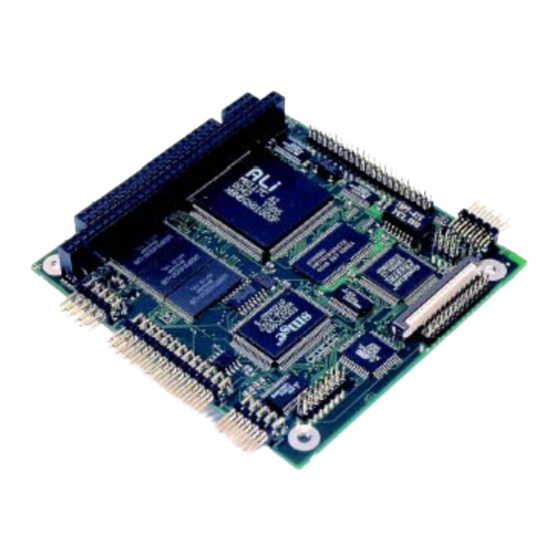
Kontron INTRODUCTION MOPS/386A The MOPS/386A integrates the complete functionality of an 80386 SX motherboard with a CPU, system BIOS, minimum 2MB DRAM, keyboard controller, real-time clock and additional peripheral functions such as serial and parallel ports, floppy interface, IDE hard- disk interface, character-LCD interface, matrix-keyboard interface, watchdog timer, and a silicon disk. -
Page 11: Pc/104 An Embedded Pc Standard
The modules' self-stacking bus can be useful to install multiple modules in one location. This facilitates product upgrades or options and allows temporary addition of modules during system debug or test. MOPS/386A User’s Guide Introduction... -
Page 12: Getting Started
Kontron GETTING STARTED The easiest way to get the MOPS/386A board running is to use a starter kit from Kontron Embedded Modules GmbH. Take the following steps: 1. Turn off the power supply (part of the starter kit). 2. Connect the power supply to the starter kit baseboard (part of the starter kit). -
Page 13: Specifications
Keyboard controller EEPROM for CMOS setup Matrix keyboard controller Alphanumeric LCD interface PC/104-Format 96 * 90 mm (3.8" x 3.6") with PC/104 ISA bus 5V-only power supply Full ISA electrical characteristics such as timing and DC characteristics MOPS/386A User’s Guide Specifications... -
Page 14: Mechanical Specifications
620mA (at 40MHz CPU clock) / 340mA (at 4MHz CPU clock) Supply Current (Maximum) 4.3.4. 1.95A (calculated theoretical value from all components maximum supply currents) Supply Current from Battery (Max.) 4.3.5. < 10µA @ 3V battery, 0..70°C, no system power < 1µA with system power on Specifications MOPS/386A User’s Guide... -
Page 15: Environmental Specifications
Note: The maximum operating temperature is the maximum measurable temperature on any spot on the module’s surface. You must maintain the temperature according to the above specification. Humidity 4.4.2. Operating: 10% to 90% (noncondensing) Nonoperating: 5% to 95% (noncondensing) MOPS/386A User’s Guide Specifications... -
Page 16: Cpu, Chipset And Super I/O Controller
Kontron CPU, CHIPSET AND SUPER I/O CONTROLLER CPU and Chipset The MOPS/386A features an ALi M6117C single chip that includes a highly integrated, low voltage implementation of Intel’s™ 386SX compatible microprocessor (40MHz), plus Ali’s M1217B chipset. The M6117C provides the following functions: Static Intel™... -
Page 17: Super I/O Controller Configuration
Note: The Super I/O Controller is connected to the ISA address lines A0 to A10. Therefore, the I/O port addresses of the SMsC FDC37C669 will be mirrored every 800hex in the I/O address apace. MOPS/386A User’s Guide CPU, Chipset and Super I/O Controller... -
Page 18: System Memory
Kontron SYSTEM MEMORY The MOPS/386A comes with onboard soldered 2MB of DRAM (EDO). The memory is not upgradeable by the customer. Upon request, Kontron can equip the board with 8MB of DRAM (EDO) instead of 2MB. Eight MB versions are not a standard product. -
Page 19: Pc/104 Bus
C19 and D19. The pinout between PC/104 bus and AT ISA bus is identical between C1 - C18 and D1 - D18. The MOPS/386A features both – XT bus and AT bus extension – on two, dual-row socket connector with 2.54mm x 2.54mm grid (0.1" x 0.1"). -
Page 20: Configuration
I/O address ranges to avoid resource conflicts, which are often the reason for a board or a feature not functioning correctly. See the Appendix B: System Resource Allocation for information about the resources already used by the MOPS/386A. PC/104 Bus... -
Page 21: Serial-Communication Interface
Data Terminal Ready Ring Indicator Signal Ground To find the location of the serial ports on the MOPS/386A board, please see the Appendix E: Connector Layout chapter. Configuration You can set the two serial input/output interfaces to base I/O-address 3F8h, 2F8h, 3E8h, 2E8h, AUTO or disabled. -
Page 22: Parallel-Communication Interface
18 - 25 18,20 Signal Ground 18 - 25 22,24 Signal Ground 18 - 25 To find the location of the parallel port on the MOPS/386A board, please see the Appendix E: Connector Layout chapter. Parallel Communication Interface MOPS/386A User’s Guide... -
Page 23: Configuration
Kontron Configuration The parallel-port mode, I/O addresses, and IRQs are changeable in the MOPS/386A BIOS Setup Utility. You can program the base I/O-address 378h, 3BCh, 278h, disable the interface or set it to AUTO. You can choose IRQ5 or IRQ7 as the parallel-port interrupt. -
Page 24: Keyboard And Feature Interface
Keyboard data KBCLK Keyboard clock Ground BATT Battery in (3,6V) PWRGOOD Powergood To find the location of the keyboard and feature connector on the MOPS/386A board, please see the Appendix E: Connector Layout chapter. Keyboard and Feature Interface MOPS/386A User’s Guide... -
Page 25: Signal Descriptions
KBDAT (Keyboard Data) 10.2.5. Bi-directional I/O pin on CPU modules Keyboard data signal KBCLK (Keyboard Clock) 10.2.6. Bi-directional I/O pin on CPU modules Keyboard clock signal MOPS/386A User’s Guide Keyboard and Feature Interface... -
Page 26: Batt (System Battery Connection)
EEPROM and will not get lost, even without a battery connected. Example Connection AT-keyboard and Other Functions 10.2.8. 1 (Speaker) 2 (GND) 3 (/RESIN) 4 (/KBLOCK) 5 (KBDATA) 6 (KBCLK) 7 (GND) 8 (VCC) 9 (BATT) Keyboard and Feature Interface MOPS/386A User’s Guide... -
Page 27: Configuration
Kontron Configuration 10.3 Refer to the Keyboard Features submenu in the Appendix B: BIOS chapter for information on configuration. MOPS/386A User’s Guide Keyboard and Feature Interface... -
Page 28: Ps/2 Mouse Interface (Optional)
Mouse data Ground MSCLK Mouse clock To find the location of the PS/2 mouse connector on the MOPS/386A board, please see the Appendix E: Connector Layout chapter. Configuration 11.2 You can set the PS/2 mouse to enabled, disabled or autodetect from the BIOS Setup. If you enable the mouse, the IRQ12 is used as the interrupt and is no longer available for other devices. -
Page 29: Floppy-Drive Interface
/TRK0 Track 00 Ground /WRPRT Write Protect Ground /RDATA Read Data Ground /CHDSEL Side One Select To find the location of floppy-drive interface on the MOPS/386A board, please see the Appendix E: Connector Layout chapter. MOPS/386A User’s Guide Floppy-Drive Interface... -
Page 30: Connector Diagram
1.44MB or 2.88MB. Refer to the Main Menu section of the Appendix B: BIOS Operation chapter for more information on configuring the floppy drive. You also can disable the floppy-disk interface in the I/O Device Configuration Submenu. Floppy-Drive Interface MOPS/386A User’s Guide... -
Page 31: Ide Interface
Part Number 96021-0000-00-0) or a 3.5” form factor (KAB-IDE-25, Part Number 96020- 0000-00-0). You can plug a Kontron chipDISK, which is an IDE hard disk that uses Flash technology, into the IDE interface and mechanically mount it by using a mini spacer on the chipDISK hole. -
Page 32: Configuration
Ground VCC (Motor) Ground Not connected To find the location of IDE-controller interface on the MOPS/386A board, please see the Appendix E: Connector Layout chapter. Configuration 13.2 The IDE interface offers several configuration settings. Refer to the Main Menu and I/O Device Configuration Submenu in the Appendix B: BIOS Operation chapter for additional information on configuration. -
Page 33: Silicon-Disk Interface
Use a Kontron chipDISK as an add-on module on the IDE interface if you require a Flash disk for other operating systems. Set the silicon disk to disabled when not used. -
Page 34: Initialization
‘Erase On Next Boot’ option in the BIOS setup screen, you must run the SSDINIT.EXE utility to create a DOS partition. The SSDINIT.EXE utility, which you can download from the Kontron Web site, is self-explanatory. Note: Do not use FDISK or other disk-partitioning tools to create partitions on the Flash disk. -
Page 35: Ethernet Interface
Unused Unused RXD- 10BASE-T Receive Differential Input LNLED LAN LED Output LKLED Link LED Output To find the location of the Ethernet controller on the MOPS/386A board, please see the Appendix E: Connector Layout chapter. MOPS/386A User’s Guide Ethernet Interface... -
Page 36: Signal Descriptions
15.3 A setup utility, which is part of the driver package, can configure the Ethernet controller. You can download the driver from the Kontron Web site. For further information read the read-me file or contact technical support. Ethernet Technical Support 15.4... -
Page 37: Power Connection
The following table shows the pinout. Header Signal Name Function Ground BATT Battery +12V +12V -12V -12V Ground To find the location of the power connector on the MOPS/386A board, please see the Appendix E: Connector Layout chapter. MOPS/386A User’s Guide Power Connection... -
Page 38: Power Pins
Modules on the PC/104 bus consuming a higher supply current must provide power supply through an additional connector. Note: The MOPS/386A is not a replacement for a backplane. Use all power pins on the power connector and on the PC/104 connector for power supply to the MOPS/386A, and also use all additional power connectors on additional I/O cards, if your system exceeds the above limitations. -
Page 39: External Battery
You can connect an external battery to Pin 3 (BATT) of the power connector instead of Pin 9 of the KBD connector. Note: The two battery inputs are directly connected and should only be used exclusively. MOPS/386A User’s Guide Power Connection... -
Page 40: Lcd Dot-Matrix Interface
Kontron LCD DOT-MATRIX INTERFACE To connect a LCD dot-matrix display, the MOPS/386A offers an interface with 16 signals. This interface can support character LCDs for up to 40 columns and four rows, which are equipped with a Hitachi HD44780 controller or a compatible one. A BIOS extension of the MOPS/386A controls the outputs to the display via software interrupt INT10hex. -
Page 41: Backlight
Backlight - Negative supply voltage for backlight (GND). Backlight 17.2 A series resistor (4Ω) connects Pin 15 with VCC (+5V). You can plug in a LED backlight directly on Pin 15 and Pin 16. MOPS/386A User’s Guide LCD Dot-Matrix Interface... -
Page 42: Configuration
Because the LCD dot-matrix display is driven by parallel-port signals and needs to exchange data with the MOPS/386A BIOS extension, the parallel port must be set to bi- directional mode. We recommend using the EPP mode. Please refer to the I/O Device Configuration Submenu in the Appendix B: BIOS Operation chapter for additional information on configuration of the parallel port. -
Page 43: Touch-Matrix Interface
Matrix Keyboard Controller 18.1 The MOPS/386A comes with a matrix keyboard controller, which can control an 8*10 (80 keys) matrix keyboard or matrix touch screen that fully parallels a standard keyboard. You do not need additional driver software to support this feature because the matrix support is fully integrated in the onboard BIOS. -
Page 44: Connector
Do not Do not connect connect anything. anything. I2DAT/RB6 Reserved. Do not connect anything. To find the location of the matrix keyboard connector on the MOPS/386A board, please see the Appendix E: Connector Layout chapter. Matrix-Keyboard Interface MOPS/386A User’s Guide... -
Page 45: Standard Matrix Keyboard
To connect a matrix keyboard, wire outputs Y0-Y7 with matrix lines and inputs RA0-RA4, RB0-RB4 with matrix columns. The matrix controller of the MOPS/386A has a cyclic output of a low level on the Y0 to Y7 lines. Whenever a connection (shortcut) on the matrix keyboard is made, an input line will go low. -
Page 46: Enhanced Matrix Keyboard
If you need a larger matrix, you can enhance the matrix to 16*10 crossings. To achieve this, you will need external circuitry, which is shown in the following diagram. 18.5 74HCT 164 MCLR/ ENPBLT MCLR/ ENPBLT MOPS/386A Adapterboard Matrix Matrix-Keyboard Matrix-Keyboard Interface MOPS/386A User’s Guide... -
Page 47: Configuration
This configuration is done with the P389MTX.EXE utility program, which you can download from the Kontron Web site. This program allows you to assign a scan code or extended scan codes to any crosspoint on the matrix. -
Page 48: Scan Codes Of A Mf2 Keyboard
The following scan codes are in hex. 3B 3C 3D 3E 09 0A 0B 0C 0D 19 1A 1B 1E 1F 28 2B 2A 56 2C 2D 2E 2F Note: * This key cannot be used on a matrix keyboard Matrix-Keyboard Interface MOPS/386A User’s Guide... -
Page 49: Watchdog Timer
Kontron WATCHDOG TIMER The watchdog timer is integrated in the chipset of the MOPS/386A and can issue a reset to the system or generate a nonmaskable interrupt (NMI). The watchdog timer circuit has to be triggered within a specified time by the application software. If the watchdog is not triggered because proper software execution fails or a hardware malfunction occurs, it will reset the system or generate the NMI. -
Page 50: Appendix A: System-Resource Allocations
Some PC/104 add-on board manufacturers do not follow the P996 Specification and allow shareable interrupts. If you want to use such PC/104 boards with Kontron devices, contact the manufacturer of the add-on board and ask about switching to non interrupt sharing. -
Page 51: Direct Memory Access (Dma) Channels
(2) The DMA channel is only used in ECP mode; it is free in other modes. Memory Map 20.3 The MOPS/386A processor module can come with up to 8MB of memory. The first 640KB of DRAM are used as main memory. Using DOS, you can address 1MB of memory directly. Memory area above 1MB (high memory, extended memory) is accessed under DOS via special drivers such as HIMEM.SYS... - Page 52 SSD Flash If the onboard SSD is disabled in setup, the EFFFFh pages and area is free for other devices to use (ISA bus tables only, no shadow RAM). F0000h – System FFFFFh BIOS System Resource Allocations MOPS/386A User’s Guide...
-
Page 53: Using Expanded Memory Managers
EMS frames, which is most of the time done by using special exclusion parameters. When using the MOPS/386A with the onboard silicon disk enabled, an EMM has to be loaded in the CONFIG.SYS, the memory area E0000h to EFFFFh has to be excluded. -
Page 54: I/O Address Map
I/O Address Map 20.4 The I/O-port addresses of the processor module MOPS/386A are functionally identical to a standard PC/AT. All addresses not mentioned in this table should be available. We recommend that you do not use I/O addresses below 0110hex with additional hardware for compatibility reasons, even if they are available on the MOPS/386A. -
Page 55: Appendix B: Bios Operation
Kontron APPENDIX B: BIOS OPERATION The MOPS/386A comes with a Phoenix BIOS, which is located in an onboard Flash EEPROM in compressed form. The device has 8-bit access. Faster access (16 bit) is provided by the shadow RAM feature. The onboard Flash EEPROM also holds some special Kontron BIOS extensions, which are loaded during boot up if the corresponding feature is enabled. -
Page 56: Setup Guide
The BIOS setup menus documented in this section represent those found in most models of the MOPS/386A. The BIOS setup for specific models can differ slightly. Note: Selecting incorrect values may cause system boot failure. Load setup-default values to recover by pressing <F9>. - Page 57 It updates as you move the cursor to each field. General Help Window Pressing <F1> or <ALT-F1> on a menu brings up the General Help window that describes the legend keys and their alternates. Press <Esc> to exit the General Help window. MOPS/386A User’s Guide BIOS Operation...
-
Page 58: Main Menu
Opens Memory Shadow submenu. 8Memory Shadow System Memory Displays amount of conventional memory detected during bootup. Extended Memory Displays amount of extended memory detected during bootup. Note: In the Option column, bold shows default settings. BIOS Operation MOPS/386A User’s Guide... -
Page 59: Master Or Slave Submenus
Enabling LBA uses Logical Block Addressing instead of Enabled CHS. 32-Bit I/O Disabled Enables 32-bit communication between CPU and IDE card. Enabled Requires PCI or local bus. Note: In the Option column, bold shows default settings. MOPS/386A User’s Guide BIOS Operation... -
Page 60: Jumptec Flash Disk Submenu
Accesses to this upper memory region go to the ISA bus if Enabled Disabled or to local memory if Enabled. D000 – D7FF See above. Disabled Enabled D800 - DFFF Disabled See above. Enabled Note: In the Option column, bold shows default settings. BIOS Operation MOPS/386A User’s Guide... -
Page 61: Advanced Menu
1024 cylinders, more than 16 heads or more than 63 sectors per track. Halt On Errors Determines if post errors cause the system to halt. Note: In the Option column, bold shows default settings. MOPS/386A User’s Guide BIOS Operation... -
Page 62: Advanced Chipset Control Submenu
12, 10, 4, 40 Note: In the Option column, bold shows default settings. Kontron recommends using a CPU with a clock speed of 25MHz, 33MHz or 40MHz when using the MOPS/386A with additional add-on boards. With lower CPU clocks, the MOPS/386A performance operates too slowly for proper operation of peripherals. -
Page 63: Keyboard Features Submenu
Keyboard auto-repeat ¼ sec Sets delay time after the key is pressed before it begins delay ½ sec to repeat the keystroke. ¾ sec 1 sec Note: In the Option column, bold shows default settings. MOPS/386A User’s Guide BIOS Operation... -
Page 64: I/O Device Configuration Submenu
DMA Channel 3 can be used for ECP mode only. 8Watchdog Submenu Opens Watchdog Settings submenu. Settings Keyboard Matrix Disabled Enables the onboard keyboard matrix controller. Enabled Note: In the Option column, bold shows default settings. BIOS Operation MOPS/386A User’s Guide... -
Page 65: Watchdog Settings Submenu
Watchdog Settings Submenu 21.5.5. Feature Option Description Mode Disabled Select watchdog operation mode. Reset Timeout 0.4s, 1s, 5s, 10s, Maximum trigger period. 30s, 1min, 5min, 10min Note: In the Option column, bold shows default settings. MOPS/386A User’s Guide BIOS Operation... -
Page 66: Security Menu
In the Option column, bold shows default settings. Enabling Supervisor Password requires a password for entering Setup. Passwords are not case-sensitive. User and Supervisor passwords are related. You can only create a user password if a supervisor password exists. BIOS Operation MOPS/386A User’s Guide... -
Page 67: Boot Menu
* If you enable dark boot, the screen stays blank until the OS loads unless: a) You press <Escape> to display the POST screen. b) You press <F2> to enter setup. c) POST issues an error message. d) The BIOS or an option ROM requests keyboard input. MOPS/386A User’s Guide BIOS Operation... -
Page 68: Exit Menu
Load Setup Defaults Select to display default values for all Setup menus. Discard Changes Discards changes made during a Setup session and reverts to values previously saved in CMOS. Save Changes Saves all selections without exiting Setup. BIOS Operation MOPS/386A User’s Guide... -
Page 69: Kontron Bios Extensions
Kontron BIOS Extensions 21.9 Besides the Phoenix System BIOS, the MOPS/386A comes with a few BIOS extensions that support special features. All extensions are located in the onboard flash EEPROM. Some extensions are permanently available; some are loaded if required during boot up. -
Page 70: Remote Control Client Extension
Part Number 96047-0000-00-0). This software tool can communicate with the board via one of the serial ports. During boot up of the MOPS/386A, the system BIOS scans the serial ports for an available JRC connection. If detected, it loads the JRC client BIOS extension into the memory. -
Page 71: Silicon Disk Bios Extension
Silicon Disk BIOS extension 21.9.3. The system BIOS setup of the MOPS/386A allows you to enable the onboard silicon disk as a bootable Flash disk. When the Interrupt 13h drive mapping is enabled, the Silicon Disk BIOS extension loads during boot up. The Flash Disk is a BIOS INT 13h compatible implementation of a solid-state disk. -
Page 72: Updating Or Restoring Bios
Updating or Restoring BIOS 21.10 If your MOPS/386A board requires a newer BIOS version or the BIOS is damaged, you may need to update or restore the BIOS. Phoenix PHLASH allows you to update or restore the BIOS with a newer version or restore a corrupt BIOS by using a floppy disk without having to install a new ROM chip. -
Page 73: Preventing Problems When Updating Or Restoring Bios
For further information on the update key and the crisis diskette, see a special application note (PHLASH_E???.PDF), which is available from the Kontron Web site. (The three question marks indicate the revision number of the document.) MOPS/386A User’s Guide... -
Page 74: Appendix C: Block Diagram
Kontron APPENDIX C: BLOCK DIAGRAM Block Diagram MOPS/386A User’s Guide... -
Page 75: Appendix D: Mechanical Dimensions
You can use a pair of 104-pin male and female stacking connectors to connect two PC/104 bus boards. (All dimensions below are in mm.) 63.67 40.54 14.89 8.89 4.01 1.75 5.05 6.35 11.43 26.67 85.09 90.17 MOPS/386A User’s Guide Mechanical Dimensions... -
Page 76: Appendix E: Connector Layout
DRAM FLASH 3 Embedded FLASH 2 FLASH 1 Power PC/104 Bus (XT-Bus part) PC/104 Bus (AT-Bus part) Pin 1 of any connector is marked with a rectangular pad at the bottom side of the board. Connector Layout MOPS/386A User’s Guide... -
Page 77: Connector Functions And Interface Cables
Ethernet Interface 2mm 8 pos. KAB-MOPS-ETN1 For RJ45 Connector (Berg 90311-008 or (PN 96048-0000-00-0) adaptation. compatible) Serial Interface 2.54mm 10 pos. KAB-DSUB9-2 For DSUB 9 COM B Connector (AMP 1-215882-0 or (PN 96017-0000-00-0) adaptation. compatible) MOPS/386A User’s Guide Connector Layout... -
Page 78: Pinout Table
SA12 /REFRESH /ACK SA11 SYSCLK /TRK0 SA10 IRQ7 /BUSY IRQ6 /WRPRT IRQ5 /IWT IRQ4 /RDATA IRQ3 /IRT /SLCT /DACK2 /HDSEL IOCHRDY BALE BALE IRQ14 /IOCS16 /IDECS0 /IDECS1 Note: LPT Pin 26 is connected to VCC. Connector Layout MOPS/386A User’s Guide... - Page 79 /KBLOCK MSCLK TXD1 TXD2 KBDAT /CTS1 /CTS2 RXD- KBCLK Enable /DTR1 /DTR2 LNLED /RI1 /RI2 LKLED BATT PWRGOOD Backlight + Backlight - /MCLR ENPBLT I2CLK/RB5 I2DAT/RB6 Note: COMA and COMB PIN10 are connected to VCC. MOPS/386A User’s Guide Connector Layout...
-
Page 80: Appendix F: Pc Architecture Information
SIG on the Web. PCI & PCI-X Hardware and Software Architecture & Design, Fifth Edition, Edward Solari and George Willse, Annabooks, 2001, ISBN 0-929392-63-9. PCI System Architecture, Tom Shanley and Don Anderson, Addison-Wesley, 2000, ISBN 0-201-30974-2. PC Architecture Information MOPS/386A User’s Guide... -
Page 81: General Pc Architecture
You can search for information about the working group on the Web. We recommend you also search the Web for information on 4.2 I/O cable, if you use hard disks in a DMA3 or PIO4 mode. MOPS/386A User’s Guide PC Architecture Information... -
Page 82: Usb
The Programmer’s PC Sourcebook, Second Edition, Thom Hogan, Microsoft Press, 1991, ISBN 1-55615-321-X Undocumented PC, A Programmer’s Guide to I/O, CPUs, and Fixed Memory Areas, Frank van Gilluwe, Second Edition, Addison-Wesley, 1997, ISBN 0-201-47950-8 PC Architecture Information MOPS/386A User’s Guide... -
Page 83: Appendix G: Document-Revision History
Kontron APPENDIX G: DOCUMENT-REVISION HISTORY Revision Date Edited by Changes P389M110 14.12.2001 Created manual. P389M111 30.06.2003 JL/BHO Updated manual with technical information and Kontron name change throughout the manual. MOPS/386A User’s Guide Document-Revision History...
Need help?
Do you have a question about the MOPS/386A and is the answer not in the manual?
Questions and answers