Table of Contents
Advertisement
Advertisement
Table of Contents

Related Manuals for Kontron KTQ77/Flex


Summary of Contents for Kontron KTQ77/Flex
- Page 1 KTQ77/Flex Users Guide KTD-N0848-B If it’s embedded, it’s Kontron...
-
Page 2: Document Revision History
Copyright 2011, KONTRON Technology A/S, ALL RIGHTS RESERVED. No part of this document may be reproduced or transmitted in any form or by any means, electronically or mechanically, for any purpose, without the express written permission of KONTRON Technology A/S. Trademark Acknowledgement: Brand and product names are trademarks or registered trademarks of their respective owners. - Page 3 KONTRON Technology warrants its products to be free from defects in material and workmanship during the warranty period. If a product proves to be defective in material or workmanship during the warranty period, KONTRON Technology will, at its sole option, repair or replace the product with a similar product.
-
Page 4: Table Of Contents
KTQ77 Graphics Subsystem ....................... 21 Intel® HD Graphics 4000/2500 ....................... 21 2.5.1 Power Consumption ........................22 Connector Locations ................25 KTQ77/Flex – frontside ........................25 KTQ77/Flex - backside ........................26 Connector Definitions ................ 27 IO-Area Connectors ................28 Display connectors (IO Area) ......................28 Analogue VGA (VGA) ........................ - Page 5 PCI-Express x4 Connector (PCIe x4) (J33) ..................58 7.1.4 PCI Slot Connectors ........................59 Signal Description – PCI Slot Connector ................... 60 7.2.1 KTQ77 PCI IRQ & INT routing ......................61 7.2.2 On-board - & mating connector types ........... 62 System Resources ................63 KTQ77/Flex Users Guide...
- Page 6 10.4.1 CSM16 parameters ........................134 10.4.2 Force Boot Setup ......................... 135 10.4.3 CSM parameters ........................... 136 Security ............................137 10.5 10.5.1 HDD Security Configuration ......................138 Save & Exit ........................... 139 10.6 11 AMI BIOS Beep Codes ............... 140 KTQ77/Flex Users Guide...
- Page 7 KTD-N0848-B Page 7 12 OS Setup ..................141 KTQ77/Flex Users Guide...
-
Page 8: Introduction
KTD-N0848-B Page 8 Introduction Introduction This manual describes the KTQ77/Flex board made by KONTRON Technology A/S. The board will also be denoted KTQ77 in this manual. The KTQ77 board is based on the Q77 chipset, support 2 and 3 generation Intel® i7 -, i5 -, i3 2Core and 4Core processors and also Pentium and Celeron processors. -
Page 9: Installation Procedure
1 Installation procedure 1.1 Installing the board To get the board running, follow these steps. If the board shipped from KONTRON has already components like DRAM, CPU and cooler mounted, then relevant steps below, can be skipped. 1. Turn off the PSU (Power Supply Unit) Warning: Turn off PSU (Power Supply Unit) completely (no mains power connected to the PSU) or leave the Power Connectors unconnected while configuring the board. -
Page 10: Requirement According To Iec60950
Paristo voi räjähtää, jos se on virheellisesti Explosionsfara vid felaktigt batteribyte. asennettu. Använd samma batterityp eller en ekvivalent Vaihda paristo ainoastaan laltevalmistajan typ som rekommenderas av apparattillverkaren. suosittelemaan Kassera använt batteri enligt fabrikantens tyyppiin. Hävitä käytetty paristo valmistajan instruktion. ohjeiden mukaisesti. KTQ77/Flex Users Guide... -
Page 11: System Specification
Page 11 System Specification 2 System Specification 2.1 Component main data The table below summarizes the features of the KTQ77/Flex embedded motherboard. Form factor KTQ77/Flex: Flex-ATX (190,5 mm by 228,6 mm) Processor Support the following Intel® Core™ processors via Socket H2 (LGA1155), ZIF Socket •... - Page 12 DAC, ADC, PWM and TIMER (Multiplexed), (via Feature connector) • • WAKE UP / Interrupt Inputs (Multiplexed), (via Feature connector) • 3 Wire Bus for GPIO Expansion (up to 152 GPIOs), (via Feature connector) • 8 bit Timer output, (via Feature connector) KTQ77/Flex Users Guide...
- Page 13 Support • WES7 (32b * + 64b *) • Linux Fedora * • Linux Ubuntu * (RAID problem) • VxWorks BSP, WES7 BSP, Kontron Linux BSP (not ready yet) *= Out Of The Box installation test only KTQ77/Flex Users Guide...
- Page 14 Business Equipment Product Category CCN: NWGQ2, NWGQ8 File number: E194252 Theoretical MTBF: 216227 / 100903 hours @ 40ºC / 60ºC for the KTQ77/Flex Restriction of Hazardous Substances (RoHS): All boards in the KTQ77 family are RoHS compliant. Capacitor utilization: No Tantalum capacitors on board Only Japanese brand Solid capacitors rated for 100 ºC used on board...
-
Page 15: System Overview
2.2 System overview The block diagram below shows the architecture and main components of the KTQ77. The key ® component on the board is the Intel Q77 (Panther Point) Express Chipset. More detailed block diagram on next page. KTQ77/Flex Users Guide... - Page 16 (4x Gen 3.0 / 2.0) Q77 PCH 6x SATA PCIe x4 Slot SDVO to LVDS (option) mSATA PCIe Mini Card VIA Codec PCI slot PCI slot IO controller IO controller ITE8516 W83627DHG-P(T) COM1/2 FAN CPU/SYS FEATURE COM3/4 KTQ77/Flex Users Guide...
-
Page 17: Processor Support Table
CPU’s are indicated by text. Some processors in the list are distributed from Kontron, those CPU’s are marked by an * (asterisk). However please notice that this marking is only guide line and maybe not fully updated. Processor... - Page 18 Intel® Turbo Boost Technology 2.0 is supported by i5 and i7, as indicated in above list of processors, and is enabling overclocking of all cores, when operated within the limits of thermal design power, temperature and current. KTQ77/Flex Users Guide...
- Page 19 Different coolers are available on the market and some is not generating any airflow or is blocking the airflow around these components, causing reduced lifetime. It is recommended to use a cooler like the Kontron PN 1046-6305 “KTQ77 Cooler”.
-
Page 20: System Memory Support
KTD-N0848-B Page 20 System Specification 2.4 System Memory support The KTQ77/FLEX has four DDR3 UDIMM sockets. The sockets support the following memory features: • 4x DDR3 1.5V UDIMM 240-pin • Dual-channel with 2 UDIMM per channel • Single/dual rank unbuffered 1333/1600MT/s (PC3-10600/PC3-12800) -
Page 21: Ktq77 Graphics Subsystem
The HDMI interface supports the HDMI 1.4a specification and includes audio codecs. However limitations to the resolution apply: 2048x1536 VGA 1920x1200 HDMI and DVI DP to VGA DP to HDMI DP to DVI-D PN 1045-5779 PN 1045-5781 PN 1045-5780 KTQ77/Flex Users Guide... -
Page 22: Power Consumption
SATA disks, Intel i7 CPU, 4x DIMM 2GB Modules, DP Monitor, Keyboard & Mouse, 3x 1-4GB USB Flash Stick, 3x 1GB LAN. KTQ77 ATX supplies Current Probe Tektronix DPO 2024 Note: The Power consumption of Display and HD are not included. KTQ77/Flex Users Guide... - Page 23 Current draw Power consumption +12V +12V P4 +3V3 -12V 5VSB < 100mA <0.5W Total <0.5W S4 Mode, Mean, No external load Supply Current draw Power consumption +12V +12V P4 +3V3 -12V 5VSB < 100mA <0.5W Total <0.5W KTQ77/Flex Users Guide...
- Page 24 Current draw Power consumption +12V +12V P4 +3V3 -12V 5VSB < 100mA <0.5W Total <0.5W S4 Mode, Mean, No external load Supply Current draw Power consumption +12V +12V P4 +3V3 -12V 5VSB < 100mA <0.5W Total <0.5W KTQ77/Flex Users Guide...
-
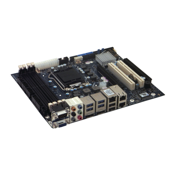
Page 25: Connector Locations
KTD-N0848-B Page 25 Connector Location 3 Connector Locations 3.1 KTQ77/Flex – frontside DDR3 A0 J12 (not used) Sata5 - Sata0 - Sata1 Sata2 - Sata3 - Sata4 ATX/ BTXPWR Feature (see note) DDR3 A1 XDP-PCH LVDS (backside) SPI recover ClrCMOS... -
Page 26: Ktq77/Flex - Backside
KTD-N0848-B Page 26 Connector Location 3.2 KTQ77/Flex - backside LPT (*) XDP-CPU (*) XDP-PCH (*) (*) The LPT connector and the XDP connectors are not mounted in volume production. KTQ77/Flex Users Guide... -
Page 27: Connector Definitions
On-board pull-up or pull-down resistors on input pins or open-collector output pins. Note Special remarks concerning the signal. The abbreviation TBD is used for specifications which are not available yet or which are not sufficiently specified by the component vendors. KTQ77/Flex Users Guide... -
Page 28: Io-Area Connectors
12 DDCDAT Display Data Channel Data. Used as data signal to/from monitors with DDC interface. 13 HSYNC CRT horizontal synchronization output. VSYNC CRT vertical synchronization output. 15 DDCCLK Display Data Channel Clock. Used as clock signal to/from monitors with DDC interface. KTQ77/Flex Users Guide... -
Page 29: Dp Connectors (Dp0/Dp1)
AUX (-) channel used by DP Aux Ch (n) or DDC Data DDC Data used by HDMI Hot Plug Internally pull down (100Kohm). Return PWR Same as GND Fused by 1.5A resetable PTC fuse, common for DP0 and 3.3V KTQ77/Flex Users Guide... -
Page 30: Ethernet Connectors (Io Area)
Ethernet connector 1 (ETH1) is mounted together with USB Ports 4 and 5. Ethernet connector 2 (ETH2) is mounted together with and above Ethernet connector 3 (ETH3). The pinout of the RJ45 connectors is as follows: Signal Type Ioh/Iol Note MDI0+ MDI0- MDI1+ MDI2+ MDI2- MDI1- MDI3+ MDI3- KTQ77/Flex Users Guide... -
Page 31: Usb Connectors (Io Area)
USB Port 4 and 5 (via EHCI1) are supplied on the combined ETH1, USB4 and USB5 connector. Note: For USB2.0 cabling it is required to use only HiSpeed USB cable, specified in USB2.0 standard: For USB3.0 cabling it is required to use only HiSpeed USB cable, specified in USB3.0 standard: KTQ77/Flex Users Guide... -
Page 32: Usb Connector 0/1 (Usb0/1)
Differential pair works as Data/Address/Command Bus. USB1+ USB1- RX1+ RX1- TX1+ TX1- 5V supply for external devices. SB5V is supplied during powerdown to allow 5V/SB5V wakeup on USB device activity. Protected by resettable 1A fuse covering both USB ports. KTQ77/Flex Users Guide... -
Page 33: Usb Connector 2/3 (Usb2/3)
USB4+ USB4- Differential pair works as Data/Address/Command Bus. USB5+ USB5- 5V supply for external devices. SB5V is supplied during powerdown to allow wakeup 5V/SB5V on USB device activity. Protected by resettable 1A fuse covering both USB ports. KTQ77/Flex Users Guide... -
Page 34: Audio Connector (Io Area)
Front speaker out Front speaker out Pink Mic in Mic in Mic in Mic in Audio header Side speaker out Audio header Rear speaker out Rear speaker out Rear speaker out Audio header Center/ Subwoofer Center/ Subwoofer KTQ77/Flex Users Guide... -
Page 35: Com1 Connector (Io Area)
Data Carrier Detect, indicates that the modem or data set has detected the data carrier. Ring Indicator, indicates that the modem has received a ringing signal from the telephone line. The pinout of Serial ports COM1 is as follows: Pull Pull Note Ioh/Iol Type Signal PIN Signal Type Ioh/Iol Note KTQ77/Flex Users Guide... -
Page 36: Internal Connectors
5V and 3V3 supplies. These supplies are not supervised on-board. PS_ON# Active low open drain signal from the board to the power supply to turn on the power supply outputs. Signal must be pulled high by the power supply. KTQ77/Flex Users Guide... -
Page 37: Fan Connectors (Fan_Cpu) (J28) And (Fan_Sys) (J29)
On-board is a pull-up resistor 4K7 to +12V. The signal has to be pulsed, typically twice per rotation. +12V supply for fan. A maximum of 2000mA can be supplied from this pin. Power Supply GND signal KTQ77/Flex Users Guide... -
Page 38: Ps/2 Keyboard And Mouse Connector (Kbdmse) (J15)
Bi-directional serial data line used to transfer data from or commands to the PS/2 mouse. KDBCLK Bi-directional clock signal used to strobe data/commands from/to the PC-AT keyboard. Bi-directional serial data line used to transfer data from or commands to the PC-AT KBDDAT keyboard. KTQ77/Flex Users Guide... -
Page 39: Display Connectors (Internal)
Inverter end of the cable kit, the noise is limited and the picture is stable. If the Backlight Enable is required to be active high, then check the following BIOS Chipset setting: Backlight Signal Inversion = Enabled. KTQ77/Flex Users Guide... -
Page 40: Sata (Serial Ata) Disk Interface (J22 - J27)
The signals used for the primary SATA hard disk interface are the following: Signal Description SATA* RX+ Host transmitter differential signal pair SATA* RX- Host receiver differential signal pair SATA* TX+ SATA* TX- “*” specifies 0, 1, 2, 3, 4, 5 depending on SATA port. KTQ77/Flex Users Guide... -
Page 41: Usb Connectors (Usb)
USB8+ USB8- Differential pair works as Data/Address/Command Bus. USB9+ USB9- 5V supply for external devices. SB5V is supplied during powerdown to allow wakeup on USB device activity. Protected by resettable 1A fuse covering both USB 5V/SB5V ports. KTQ77/Flex Users Guide... -
Page 42: Usb Connector 10/11 (Usb10/11) (J17)
5V supply for external devices. SB5V is supplied during powerdown to allow wakeup on USB device activity. Protected by resettable 1A fuse covering both USB 5V/SB5V ports. Note 1: In order to meet the requirements of USB standard, the 5V input supply must be at least 5.00V. KTQ77/Flex Users Guide... -
Page 43: Serial Com2 - Com4 Ports (J19, J20, J21)
9 10 Note 1: The COM2, COM3 and COM4 5V supply is fused with common 1.1A resettable fuse. DB9 adapter cables (PN 821016 200mm long and 821017 100mm long) are available for implementing standard COM ports on chassis. KTQ77/Flex Users Guide... -
Page 44: Audio Connectors
Analogue GND for Left and Right CD. (This analogue GND is not shorted to the general digital GND on the board). 6.8.2 Line2 and Mic2 Line2 and Mic2 are accessible via Feature Connector, see Feature connector description. KTQ77/Flex Users Guide... -
Page 45: Audio Header Connector (Audio_Head) (J47)
Side speakers (Surround Out Left) SIDE-OUT-R Side speakers (Surround Out Right) CEN-OUT Center Speaker (Center Out channel). LFE-OUT Subwoofer Speaker (Low Freq. Effect Out). No connection MIC1 MIC Input 1 LINE1 Line 1 signals F-SPDIF-OUT S/PDIF Output AAGND Audio Analogue ground KTQ77/Flex Users Guide... -
Page 46: Front Panel Connector (Frontpnl) (J36)
Line2 is second stereo Line signals MIC2 MIC2 is second stereo microphone input. SB3V3 Standby 3.3V voltage AGND Analogue Ground for Audio Note: In order to meet the requirements of USB standard, the 5V input supply must be at least 5.00V. KTQ77/Flex Users Guide... -
Page 47: Feature Connector (Feature) (J30)
KT-API-V2 (Application Programming Interface). EGCLK Extend GPIO Clock signal EGAD Extend GPIO Address Data signal EGCS# Extend GPIO Chip Select signal, active low TMA0 Timer Output +12V Max. load is 0.75A (1.5A < 1 sec.) KTQ77/Flex Users Guide... - Page 48 O8/IOS GPIO6 PWM4/GPA4 O8/IOS GPIO7 PWM5/GPA5 O8/IOS GPIO8 ADC0/GPI0 AI/IS GPIO9 ADC1/GPI1 AI/IS GPIO10 ADC2/GPI2 AI/IS GPIO11 ADC3/GPI3 AI/IS GPIO12 ADC4/WUI28/GPI4 AI/IS/IS GPIO13 RI1#/WUI0/GPD0 IS/IS/IOS GPIO14 RI2#/WUI1/GPD1 IS/IS/IOS GPIO15 TMRI0/WUI2/GPC4 IS/IS/IOS GPIO16 TMRI1/WUI3/GPC6 IS/IS/IOS GPIO17 L80HLAT/BAO/WUI24/GPE0 O4/O4/IS/IOS KTQ77/Flex Users Guide...
-
Page 49: Load Default Bios Settings" Jumper (J11)
4. Turn on power (use the Power On Button if required to boot). 5. Motherboard might automatically reboot a few times. Wait until booting is completed. 6.12 ClrRTC (J12) The ClrRTC (J12) connector is not used. Do not install any jumper in case J12 pin row is available. KTQ77/Flex Users Guide... -
Page 50: Spi Recover Jumper (J41)
Recovery SPI Flash will be Upgraded and not the BIOS Default SPI Flash. This means that in case something goes wrong (power interruption or incorrect BIOS package used etc.) when Upgrading BIOS, then the BIOS Recovery SPI Flash might get corrupted. KTQ77/Flex Users Guide... -
Page 51: Spi Connector (Spi) (J40)
The ISOLATE# input, active low, is normally NC, but must be connected to GND when ISOLATE# loading SPI flash. Power Supply to the Motherboard must be turned off when loading SPI flash. The pull up resistor is connected via diode to 5VSB. MISO Master Input, Slave Output KTQ77/Flex Users Guide... -
Page 52: Xdp-Cpu (Debug Port For Cpu) (J14)
(pads) is located on the backside of PCB and is prepared for the Molex 52435-2671 (or 52435- 2672). Signal Description Type Pull Up/Down Note OBSFN_A0 OBSFN_A1 HOOK0 HOOK1 HOOK2 HOOK3 HOOK4 HOOK5 HOOK6 HOOK7 500R (500R by 2x1K in parallel) /51R TRST# /51R /51R /51R TCK0 /51R KTQ77/Flex Users Guide... -
Page 53: Xdp-Pch (Debug Port For Chipset) (J13)
(pads) is prepared for the Molex 52435-2671 (or 52435-2672). Pin Signal Description Type Pull Up/Down Note HOOK0 RSMRST# Connected to HOOK6 HOOK1 PWRBTN# HOOK2 HOOK3 HOOK4 HOOK5 HOOK6 Connected to HOOK1 HOOK7 RESET# 500R (500R by 2x1K in parallel) 210R/100R TRST# 210R/100R 210R/100R TCK0 /51R KTQ77/Flex Users Guide... -
Page 54: Slot Connectors (Pcie, Msata, Minipcie, Pci)
+12V +12V +12V +12V SMB_CLK SMB_DATA +3V3 +3V3 SB3V3 +3V3 WAKE# RST# PCIE_x16 CLK PEG_TXP[0] PCIE_x16 CLK# PEG_TXN[0] PEG_RXP[0] CLKREQ PEG_RXN[0] PEG_TXP[1] PEG_TXN[1] PEG_RXP[1] PEG_RXN[1] PEG_TXP[2] PEG_TXN[2] PEG_RXP[2] PEG_RXN[2] PEG_TXP[3] PEG_TXN[3] PEG_RXP[3] PEG_RXN[3] CLKREQ PEG_TXP[4] PEG_TXN[4] PEG_RXP[4] KTQ77/Flex Users Guide... - Page 55 PEG_TXN[7] PEG_RXP[7] CLKREQ PEG_RXN[7] PEG_TXP[8] PEG_TXN[8] PEG_RXP[8] PEG_RXN[8] PEG_TXP[9] PEG_TXN[9] PEG_RXP[9] PEG_RXN[9] PEG_TXP[10] PEG_TXN[10] PEG_RXP[10] PEG_RXN[10] PEG_TXP[11] PEG_TXN[11] PEG_RXP[11] PEG_RXN[11] PEG_TXP[12] PEG_TXN[12] PEG_RXP[12] PEG_RXN[12] PEG_TXP[13] PEG_TXN[13] PEG_RXP[13] PEG_RXN[13] PEG_TXP[14] PEG_TXN[14] PEG_RXP[14] PEG_RXN[14] PEG_TXP[15] PEG_TXN[15] PEG_RXP[15] CLKREQ PEG_RXN[15] KTQ77/Flex Users Guide...
-
Page 56: Msata (J43)
SMB_DATA PCIE_TXP +3V3 Dual +3V3 Dual CLK_MPCIE DATA_MPCIE +1.5V RST_MPCIE# SEL_MSATA +3V3 Dual Note 1: 10K ohm pull-up to 3V3. Note 2: 2K2 ohm pull-up to 3V3 Dual. Note 3: 100K ohm pull-up to 1V8 (S0 mode) KTQ77/Flex Users Guide... -
Page 57: Minipci-Express Mpcie (J42)
WAKE# +3V3 +1.5V CLKREQ# PCIE_mini CLK# PCIE_mini CLK W_Disable# RST# PCIE_RXN +3V3 Dual PCIE_RXP +1.5V SMB_CLK PCIE_TXN SMB_DATA PCIE_TXP +1.5V +3V3 Note 1: 10K ohm pull-up to 3V3 Dual. Note 2: 2K2 ohm pull-up to 3V3 Dual. KTQ77/Flex Users Guide... -
Page 58: Pci-Express X4 Connector (Pcie X4) (J33)
PEG_RXN[1] PEG_TXP[2] B23 A23 PEG_TXN[2] B24 A24 B25 A25 PEG_RXP[2] B26 A26 PEG_RXN[2] PEG_TXP[3] B27 A27 PEG_TXN[3] B28 A28 B29 A29 PEG_RXP[3] B30 A30 PEG_RXN[3] B31 A31 B32 A32 Note 1: 10K ohm pull-up to 3V3 Dual. KTQ77/Flex Users Guide... -
Page 59: Pci Slot Connectors
KTD-N0848-B Page 59 Slot Connectors 7.2 PCI Slot Connectors KTQ77/Flex support 2 PCI slots PCI0 – PCI1 (J1 – J2). Terminal Note Type Signal Signal Type Note -12V TRST# +12V INTA# INTB# INTC# INTD# +5V (I/O) PWR GNT3# RST# CLKB... -
Page 60: Signal Description - Pci Slot Connector
Initialization Device Select is used as a chip select during configuration read and write transactions. IDSEL Device Select, when actively driven, indicates the driving device has decoded its address as the DEVSEL# target of the current access. As an input, DEVSEL# indicates whether any device on the bus has been selected. KTQ77/Flex Users Guide... -
Page 61: Ktq77 Pci Irq & Int Routing
When using the 820982 “PCI Riser - Flex - 2slot w. arbiter” the lower slot has IDSEL / IRQs routed straight through and the top slot has the routing: IDSEL=AD22, INT_PIRQ#F, INT_PIRQ#G, INT_PIRQ#H, INT_PIRQ#E. 820982 PCI Riser shall be plugged into Slot 0 and jumper in AD30. KTQ77/Flex Users Guide... -
Page 62: On-Board - & Mating Connector Types
Please also notice that standard connectors like DVI, DP, PCIe, miniPCIe, PCI, Audio Jack, Ethernet and USB is not included in the list. KTQ77/Flex Users Guide... -
Page 63: System Resources
10000000 Intel HD Graphics 0xDFA00000 0xFEAFFFFF 1F100000 PCI bus 0xDFA00000 0xDFA00FFF 1000 Motherboard resources 0x40004000 0x40004FFF 1000 System board 0x20000000 0x201FFFFF 200000 System board 0xD0000 0xE7FFF 18000 PCI bus Intel HD Graphics 0xA0000 0xBFFFF 20000 PCI bus KTQ77/Flex Users Guide... -
Page 64: Pci Devices
Q77 Chipset Intel - LPC 8086 1E02 Q77 Chipset Intel - SATA AHCI Controller 8086 1E22 Q77 Chipset Intel - SMBus 8086 10D3 82574L LAN Intel - Ethernet Controller 8086 10D3 82574L LAN Intel - Ethernet Controller KTQ77/Flex Users Guide... -
Page 65: Interrupt Usage
KTD-N0848-B Page 65 System Resources 9.3 Interrupt Usage Notes IRQ0 IRQ1 IRQ2 IRQ3 IRQ4 IRQ5 IRQ6 IRQ7 IRQ8 IRQ9 IRQ10 IRQ11 IRQ12 IRQ13 IRQ14 IRQ15 IRQ16 IRQ17 IRQ18 IRQ19 IRQ20 IRQ21 IRQ22 IRQ23 IRQ24 IRQ25 IRQ26 KTQ77/Flex Users Guide... -
Page 66: Io Map
Standard PS/2 Keyboard 0x00000062 0x00000063 Motherboard resources 0x00000061 0x00000061 System Speaker 0x00000060 0x00000060 Standard PS/2 Keyboard 0x00000044 0x0000005F Motherboard resources 0x00000040 0x00000043 System Timer 0x00000022 0x0000003F Motherboard resources 0x00000020 0x00000021 Programmable interrupt controller 0x00000000 0x0000001F Direct memory access controller KTQ77/Flex Users Guide... -
Page 67: Bios
Blue text for settings that can be changed. White text for actual setting to be changed via the control keys (Black text for settings that cannot be changed via control keys) The following table describes the changeable settings: Feature Options Description System Date MM/DD/YYYY Set the system date. System Time HH:MM:SS Set the system time. KTQ77/Flex Users Guide... -
Page 68: Advanced
The Advanced (main) menu contains submenu selections which will be described in more details on the following pages. In order to make a selection of a submenu activated the ↑↓ keys until the requested submenu becomes white color, then activate the <Enter>. KTQ77/Flex Users Guide... -
Page 69: Advanced - Pci Subsystem Settings
248 PCI Bus Clocks Disabled Enables or Disables VGA Palette Registers VGA Palette Snoop Snooping. Enabled Disabled Enables or Disables PCI Device to Generate PERR# Generation PERR#. Enabled Disabled Enables or Disables PCI Device to Generate SERR# Generation SERR#. Enabled KTQ77/Flex Users Guide... - Page 70 Unpopulated Links [Keep Link ON] Enter: Select Restore PCIe Registers [Disabled] +/- : Change Opt. F1: General Help F2: Previous Values F3: Optimized Defaults F4: Save & Exit ESC: Exit Version 2.15.1236. Copyright © 2012 American Megatrends, Inc KTQ77/Flex Users Guide...
- Page 71 S3 resume. Warning: Enabling this may cause issues with other hardware after S3 resume. Note1: Use either digit keys to enter value or +/- keys to increase/decrease value. Don’t use mix of digit keys and +/- keys. KTQ77/Flex Users Guide...
- Page 72 Hardware Autonomous Width [Enabled] Enter: Select Hardware Autonomous Speed [Enabled] +/- : Change Opt. F1: General Help F2: Previous Values F3: Optimized Defaults F4: Save & Exit ESC: Exit Version 2.15.1236. Copyright © 2012 American Megatrends, Inc KTQ77/Flex Users Guide...
- Page 73 Disabled unstable link operation. If supported by HW and Disabled, disable the Enabled HW ability to change link speed except speed Hardware Autonomous Speed rate reduction for the purpose of correcting Disabled unstable link operation. KTQ77/Flex Users Guide...
-
Page 74: Advanced - Apci Settings
SUSPEND S3 only (Suspend to RAM) button is pressed. Both S1 and S3 available… Disabled Enables or Disables Lock of Legacy Lock Legacy Resources Resources. Enabled Disabled S3 Video Repost Enables or Disables S3 Video Repost. Enabled KTQ77/Flex Users Guide... -
Page 75: Advanced - Trusted Computing
State of TPM. None Schedule an Operation for the Security Enable Take Ownership Device. NOTE: Your Computer will reboot Pending operation during restart in order to change State of the Disable Take Ownership Device. TPM Clear KTQ77/Flex Users Guide... -
Page 76: Advanced - Cpu Configuration
Windows XP SP2, SuSE Linux 9.2, RedHat Enterprise 3 Update 3.) When enabled, a VMM can utilize the additional Disabled Intel Virtualization hardware capabilities provided by Vanderpool Technology Enabled Technology. Note1: Not present if using CPU not supporting this feature. KTQ77/Flex Users Guide... - Page 77 Intel's technology for virtualization on the x86 platform. In order to support “Virtualization Technology” the CPU must support VT-x and the BIOS setting “Intel Virtualization Technology” must be enabled. Intel SMX Technology (Safer Mode Extensions Technology) is a part of the Trusted Execution Technology. KTQ77/Flex Users Guide...
-
Page 78: Advanced - Sata Configuration
Gen1 Indicates the maximum speed the SATA SATA Controller Speed Gen2 controller can support. Gen3 Note: in the above BIOS menu the functions below the submenu Software Feature Mask Configuration will be described after the submenu description. KTQ77/Flex Users Guide... - Page 79 →← : Select Screen ↑↓ : Select Item Enter: Select +/- : Change Opt. F1: General Help F2: Previous Values F3: Optimized Defaults F4: Save & Exit ESC: Exit Version 2.15.1236. Copyright © 2012 American Megatrends, Inc KTQ77/Flex Users Guide...
- Page 80 Disabled Smart Response Enable or disable Smart Response Technology Technology Enabled 2 Seconds 4 Seconds If enabled, indicates the delay of the OROM UI OROM UI Delay Splash Screen in normal status. 6 Seconds 8 Seconds KTQ77/Flex Users Guide...
- Page 81 Enable or Disable SATA Port. Enabled Hot Plug (see same function above) (see same function above) External SATA (see same function above) (see same function above) Spin Up Device (see same function above) (see same function above) KTQ77/Flex Users Guide...
-
Page 82: Advanced - Intel ® Rapid Start Technology
Entry After 10 minutes Enable RTC wake timer at S3 entry. 15 minutes 30 minutes 1 hour 2 hours Disabled Active Page Threshold Support RST with small partition. Support Enabled Disabled iFFS Display iFFS Display Save/Restore. Save/Restore Enabled KTQ77/Flex Users Guide... -
Page 83: Advanced - Intel Txt (Lt) Configuration
VT (Intel Virtualization Technology) is enabled/disabled in the menu: Advanced > CPU Configuration. VT-d can be enabled/disabled in the menu: Chipset > System Agent (SA) Configuration. Function Selection Description Disabled Enables or Disables Intel ® TXT (LT) Intel TXT support support. Enabled KTQ77/Flex Users Guide... -
Page 84: Advanced - Intel ® Anti-Theft Technology Configuration
Description Disabled Intel ® Anti-Theft Enables or Disables Intel ® AT in BIOS for Technology testing only. Enabled Intel ® Anti-Theft Set the number of times Recovery attempt (allowed 1 – 64) Technology Rec will be allowed. KTQ77/Flex Users Guide... -
Page 85: Advanced - Amt Configuration
Hide Un-Configure ME without password Confirmation (Note1) Enabled Confirmation Prompt Disabled OEMFlag Bit 14: MEBx Debug Message Output (Note1) Enabled Enable MEBx Debug Message Output. Disabled OEMFlag Bit 15: Un-Configure ME (Note1) Enabled Un-Configure ME without password. KTQ77/Flex Users Guide... - Page 86 Note2: This Watchdog function is unsupported. Recommendation, use Watchdog function present in Hardware Health Configuration menu. Note3: Only if Watchdog = Enabled. Note4: To enter number use digit keys and/or +/- keys. Note5: Only if Active Remote Assistance Process = Enabled. KTQ77/Flex Users Guide...
-
Page 87: Advanced - Acoustic Management Configuration
254 (0x80 - 0xFE) enable the feature and select most-quiet to most-performance settings along that range. Though hard drive manufacturers may support the whole range of values, the settings are allowed to be banded so many values could provide the same acoustic performance. KTQ77/Flex Users Guide... -
Page 88: Advanced - Usb Configuration
↑↓ : Select Item Device power-up delay [Auto] Enter: Select +/- : Change Opt. F1: General Help F2: Previous Values F3: Optimized Defaults F4: Save & Exit ESC: Exit Version 2.15.1236. Copyright © 2012 American Megatrends, Inc KTQ77/Flex Users Guide... - Page 89 Maximum time the device will take before it properly reports itself to the Host Controller. Auto Device power-up delay ‘Auto’ uses default value: for a Root port it is Manual 100 ms, for a Hub port the delay is taken from Hub descriptor. KTQ77/Flex Users Guide...
-
Page 90: Advanced - Smart Settings
POST. Enabled Note: S.M.A.R.T. (Self-Monitoring, Analysis and Reporting Technology; often written as SMART) is a monitoring system for computer hard disk drives to detect and report on various indicators of reliability, in the hope of anticipating failures. KTQ77/Flex Users Guide... -
Page 91: Advanced - Super Io Configuration
+/- : Change Opt. F1: General Help F2: Previous Values F3: Optimized Defaults F4: Save & Exit ESC: Exit Version 2.15.1236. Copyright © 2012 American Megatrends, Inc The 5 submenus are shown and described on the following pages. KTQ77/Flex Users Guide... - Page 92 Enable or Disable Serial Port Serial Port (COM) Enabled Auto IO=3F8h; IRQ=4; Change Settings (Note1) IO=3F8h; IRQ=3,4,5,6,7,10,11,12; Select an optimal setting for Super IO device. IO=2F8h; IRQ=3,4,5,6,7,10,11,12; IO=3E8h; IRQ=3,4,5,6,7,10,11,12; IO=2E8h; IRQ=3,4,5,6,7,10,11,12; Note1: only if Serial Port = Enabled KTQ77/Flex Users Guide...
- Page 93 Enable or Disable Serial Port Serial Port (COM) Enabled Auto IO=2F8h; IRQ=3; IO=3F8h; IRQ=3,4,5,6,7,10,11,12; Select an optimal setting for Super Change Settings (Note1) IO device. IO=2F8h; IRQ=3,4,5,6,7,10,11,12; IO=3E8h; IRQ=3,4,5,6,7,10,11,12; IO=2E8h; IRQ=3,4,5,6,7,10,11,12; Note1: only if Serial Port = Enabled KTQ77/Flex Users Guide...
- Page 94 IO=3E8h; IRQ=3,4,5,6,7,10,11,12; IO=2E8h; IRQ=3,4,5,6,7,10,11,12; Standard Serial Port Mode Change the Serial Port mode. Device Mode (Note1) IrDA 1.0 (HP SIR) Mode Select <High Speed> or <Normal mode> mode. ASKIR Mode Note1: only if Serial Port = Enabled KTQ77/Flex Users Guide...
- Page 95 IO=3E8h; IRQ=3,4,5,6,7,10,11,12; IO=2E8h; IRQ=3,4,5,6,7,10,11,12; Standard Serial Port Mode Change the Serial Port mode. Device Mode (Note1) IrDA 1.0 (HP SIR) Mode Select <High Speed> or <Normal mode> mode. ASKIR Mode Note1: only if Serial Port = Enabled KTQ77/Flex Users Guide...
-
Page 96: Advanced - Voltage Monitor
→← : Select Screen ↑↓ : Select Item Enter: Select +/- : Change Opt. F1: General Help F2: Previous Values F3: Optimized Defaults F4: Save & Exit ESC: Exit Version 2.15.1236. Copyright © 2012 American Megatrends, Inc KTQ77/Flex Users Guide... -
Page 97: Advanced - Hardware Health Configuration
Fan Min limit +/- : Change Opt. Fan Max limit F1: General Help F2: Previous Values Watchdog Function F3: Optimized Defaults F4: Save & Exit PC Speaker/Beep [Enabled] ESC: Exit Version 2.15.1236. Copyright © 2012 American Megatrends, Inc KTQ77/Flex Users Guide... - Page 98 Note8: Seconds, use digit keys to enter value. Value 0 means Watchdog is disabled. Refer to “KT-API- V2 User Manual” to control the Watchdog via API or refer to “KT-API-V2 User Manual DLL” how to control Watchdog via Windows DLL. KTQ77/Flex Users Guide...
-
Page 99: Advanced - Lan Configuration
Enabled (Upper) disable ETH2, ME Subsystem must be as well. With PXE boot Disabled ETH3 Configuration Control of Ethernet Devices and PXE boot. To Enabled (Lower) disable ETH3, ME Subsystem must be as well. With PXE boot KTQ77/Flex Users Guide... - Page 100 Disabled 0 – 15 (Note2) Set Seconds of Delay Before IPv6 PXE Boot. IPv6 Delay Time (Note1) Default 0 Seconds. Note1: Only if Network stack = Enabled. Note2: To enter number use digit keys and/or +/- keys. KTQ77/Flex Users Guide...
-
Page 101: Advanced - Delay Startup
The delay initiates if the value is different from 0, starts at the earliest possible point of the BIOS boot. For some add-on devices the BIOS boot is too fast for proper detection. In other words, the setting is meant as a possible fix to Add-on device detection problems. KTQ77/Flex Users Guide... -
Page 102: Advanced - Serial Port Console Redirection
F2: Previous Values Serial Port for Out-of-Band Management/ F3: Optimized Defaults Windows Emergency Management Services (EMS) F4: Save & Exit Console Redirection [Disabled] ESC: Exit Console Redirection Settings ► Version 2.15.1236. Copyright © 2012 American Megatrends, Inc KTQ77/Flex Users Guide... - Page 103 Redirection After BIOS POST [Always Enable] ↑↓ : Select Item Enter: Select +/- : Change Opt. F1: General Help F2: Previous Values F3: Optimized Defaults F4: Save & Exit ESC: Exit Version 2.15.1236. Copyright © 2012 American Megatrends, Inc KTQ77/Flex Users Guide...
- Page 104 The settings specify if BootLoader is selected than Legacy console redirection is disabled Always Enable Redirection After BIOS before booting to Legacy OS. Default value is POST BootLoader Always Enable which means Legacy console Redirection is enabled for Legacy OS. KTQ77/Flex Users Guide...
- Page 105 ´stop´ signal can be sent to Flow Control Hardware RTS/CTS stop the data flow. Once the buffers are empty, a ´start ‘signal can be sent to re-start the flow. Software Xon/Xoff Hardware flow control uses two wires to send start/stop signals. KTQ77/Flex Users Guide...
-
Page 106: Advanced - Cpu Ppm Configuration
Enabled Disabled CPU C6 Report Enable/Disable CPU C6 (ACPI C3) report to OS Enabled Disabled CPU C7 Report Enable/Disable CPU C7 (ACPI C3) report to OS Enabled Note1: Not present if CPU do not support Turbo Mode.. KTQ77/Flex Users Guide... -
Page 107: Chipset
→← : Select Screen ↑↓ : Select Item Enter: Select +/- : Change Opt. F1: General Help F2: Previous Values F3: Optimized Defaults F4: Save & Exit ESC: Exit Version 2.15.1236. Copyright © 2012 American Megatrends, Inc KTQ77/Flex Users Guide... -
Page 108: Pch-Io Configuration
Please fid description of the “PCI Express Configuration”, “USB Configuration” and “PCH Azalia Configuration” on the following pages. Function Selection Description Power Off Select AC Power state when power is re-applied Power On Restore AC Power Loss after a power failure. Last State KTQ77/Flex Users Guide... - Page 109 Decode. Enabled Subtractive Decode Port# Select PCI Express Subtractive Decode Root (Note2) Port. User to ensure port availability. (Note1) Note1: Only visible if “Subtractive Decode” is Enabled. Note2: To enter number use digit keys and/or +/- keys. KTQ77/Flex Users Guide...
- Page 110 Disabled: Disabled ASPM ASPM Support L0s: Force all links to L0s State L0sL1 Auto: BIOS auto configure Auto Disabled PME SCI Enable or disable PCI Express PME SCI. Enabled Auto PCIe Speed Gen1 Select PCI Express port speed. Gen2 KTQ77/Flex Users Guide...
- Page 111 USB Ports Per-Port Disable Control [Disabled] ↑↓ : Select Item Enter: Select +/- : Change Opt. F1: General Help F2: Previous Values F3: Optimized Defaults F4: Save & Exit ESC: Exit Version 2.15.1236. Copyright © 2012 American Megatrends, Inc KTQ77/Flex Users Guide...
- Page 112 Control each of the USB ports (0 – 13) Disable Control disabling. Enabled USB Port #(0-13) Disabled Disabled Disabled USB port. Enabled (Note2) Note1: Not visible if “xHCI Mode” is Disabled. Note2: Only visible if “USB Ports Per-Port Disable Control” is Enabled. KTQ77/Flex Users Guide...
- Page 113 Enable or disable internal HDMI codec for Azalia HDMI codec PortD Azalia. Enabled (Note2) Note1: Only visible if “Azalia is not Disabled. Note2: Only visible if “Azalia is not Disabled and “Azalia Internal HDMI codec” is Enabled. KTQ77/Flex Users Guide...
-
Page 114: System Agent (Sa) Configuration
Enables support for the BDAT ACPI Table. Disabled Enabled C-State Pre-Wake Controls C-State Pre-Wake feature for ARAT, in SSKPD[57] (Note2) Disabled Note 1: Only present if supported by CPU. Note 2: Only present if Ivy Bridge CPU is used. KTQ77/Flex Users Guide... - Page 115 →← : Select Screen ► ↑↓ : Select Item Enter: Select +/- : Change Opt. F1: General Help F2: Previous Values F3: Optimized Defaults F4: Save & Exit ESC: Exit Version 2.15.1236. Copyright © 2012 American Megatrends, Inc KTQ77/Flex Users Guide...
- Page 116 DVMT Total Gfx Mem 256M used by the Internal Graphics Device. Enabled Gfx Low Power Mode This option is applicable for SSF only. Disabled Enabled Graphics Performance Enable or disable Intel Graphics Performance Analyzers Analyzers Counters. Disabled KTQ77/Flex Users Guide...
- Page 117 →← : Select Screen ↑↓ : Select Item Enter: Select +/- : Change Opt. F1: General Help F2: Previous Values F3: Optimized Defaults F4: Save & Exit ESC: Exit Version 2.15.1236. Copyright © 2012 American Megatrends, Inc KTQ77/Flex Users Guide...
- Page 118 Auto: GMCH use VBT defaults. Level 1 Level n: Enabled with selected Level 2 Aggressiveness Level 3 Level. Level 4 Level 5 Hardware: Spread is controlled by chip. Spread Spectrum clock Hardware Chip Software: Spread is controlled by BIOS. Software KTQ77/Flex Users Guide...
- Page 119 VBIOS Default NTSC_M NTSC_M_J NTSC_433 PAL_B PAL_G PAL_D PAL_H PAL_I PAL_M PAL_N SECAM_L Select the ability to configure a TV2 Standard SECAM_B TV Minor Format. SECAM_D SECAM_G SECAM_H SECAM_K HDTV_STD_SMPTE_240M_1080i59 HDTV_STD_SMPTE_240M_1080i60 HDTV_STD_SMPTE_295M_1080i50 HDTV_STD_SMPTE_295M_1080p50 HDTV_STD_SMPTE_296M_720p50 HDTV_STD_SMPTE_296M_720p60 HDTV_STD_CEAEIA_7702A_480p60 HDTV_STD_CEAEIA_7702A_480i60 KTQ77/Flex Users Guide...
- Page 120 SDVO LVDS SDVO LVDS: VBIOS enables LVDS driver by eDP Port-A SDVO encoder. eDP Port-D eDP Port-A: LFP driven by Internal DisplayPort encoder from Port-A. 18 Bit Panel Color Depth Select the LFP Panel Color Depth. 24 Bit KTQ77/Flex Users Guide...
- Page 121 Enabled DMI Extended Synch Control Enable DMI Extended Synchronization. Disabled Auto Enable or disable DMI Gen 2. Enabled DMI Gen 2 Auto means Disabled for IVB A0 MB/DT and IVB B0 MB, Enabled for other CPUs. Disabled KTQ77/Flex Users Guide...
- Page 122 +/- : Change Opt. Fast PEG Init [Enabled] F1: General Help RxCEM Loop back [Disabled] F2: Previous Values PCIe Gen3 RxCTLEp Setting F3: Optimized Defaults ► F4: Save & Exit ESC: Exit Version 2.15.1236. Copyright © 2012 American Megatrends, Inc KTQ77/Flex Users Guide...
- Page 123 Enable or disable Fast PEG Init, Some Enabled Fast PEG Init optimization if not PEG devices present in cold Disabled boot. Enabled RxCEM Loop back Enable or disable RxCEM Loop back. Disabled Note 1: Only present if Ivy Bridge CPU is used. KTQ77/Flex Users Guide...
- Page 124 Lane 12 Enter: Select Lane 13 +/- : Change Opt. Lane 14 Lane 15 F1: General Help F2: Previous Values F3: Optimized Defaults F4: Save & Exit ESC: Exit Version 2.15.1236. Copyright © 2012 American Megatrends, Inc KTQ77/Flex Users Guide...
- Page 125 Lane 12 Enter: Select Lane 13 +/- : Change Opt. Lane 14 Lane 15 F1: General Help F2: Previous Values F3: Optimized Defaults F4: Save & Exit ESC: Exit Version 2.15.1236. Copyright © 2012 American Megatrends, Inc KTQ77/Flex Users Guide...
- Page 126 ↑↓ : Select Item Lane 13 Enter: Select Lane 14 +/- : Change Opt. Lane 15 F1: General Help F2: Previous Values F3: Optimized Defaults F4: Save & Exit ESC: Exit Version 2.15.1236. Copyright © 2012 American Megatrends, Inc KTQ77/Flex Users Guide...
- Page 127 The range of the setting is (0-15). This setting PCIe Gen3 RxCTLEp Setting 0-11, 12, 13-15 has to be specified based on platform design (Note1) and following the guideline. Note 1: Only present if Ivy Bridge CPU is used. KTQ77/Flex Users Guide...
- Page 128 Select DIMM timing profile that should be used. XMP Profile 1 XMP Profile 2 Auto 1067 1333 1600 Maximum Memory Frequency Selections in Memory Frequency Limiter Mhz. 1867 2133 2400 2667 Disabled ECC Support Enable or disable DDR Ecc Support. Enabled KTQ77/Flex Users Guide...
- Page 129 Channel A DIMM Control Enable or disable dims on channel A. Disable DIMM1 Disable Both DIMMS Enable Both DIMMS Disable DIMM0 Channel B DIMM Control Enable or disable dims on channel B. Disable DIMM1 Disable Both DIMMS KTQ77/Flex Users Guide...
- Page 130 →← : Select Screen ↑↓ : Select Item Enter: Select +/- : Change Opt. F1: General Help F2: Previous Values F3: Optimized Defaults F4: Save & Exit ESC: Exit Version 2.15.1236. Copyright © 2012 American Megatrends, Inc KTQ77/Flex Users Guide...
- Page 131 Version 2.15.1236. Copyright © 2012 American Megatrends, Inc Function Selection Description Enabled RC6 (Render Standby) Check to enable render standby support. Disabled Enabled RC6+(Deep RC6) Check to enable Deep RC6 (RC6+) support. Disabled Enabled GT Overclocking Support Enable or disable GT Overclocking Support. Disabled KTQ77/Flex Users Guide...
-
Page 132: Boot
F1: General Help F2: Previous Values F3: Optimized Defaults F4: Save & Exit ESC: Exit Version 2.15.1236. Copyright © 2012 American Megatrends, Inc Note: When pressing <F7> while booting it is possible manually to select boot device. KTQ77/Flex Users Guide... - Page 133 INT19 Trap Response Immediate: execute the trap right away. Postponed Postponed: execute the trap during legacy boot. Boot Option #1 (list of bootable devices) Sets the system boot order. Note: To enter number use digit keys and/or +/- keys. KTQ77/Flex Users Guide...
-
Page 134: Csm16 Parameters
Option ROM Message Set display mode for Option ROM. Keep Current BIOS reaction on INT19 trapping by Option ROM: Immediate INT19 Trap Response Immediate: execute the trap right away. Postponed Postponed: execute the trap during legacy boot. KTQ77/Flex Users Guide... -
Page 135: Force Boot Setup
Note 2: Only shown if SATA Port is selected. Note 3: Only shown if Device Name is selected. Note 4: By +/- key select requested port number. Make sure only valid number (0 – 5) is selected. KTQ77/Flex Users Guide... -
Page 136: Csm Parameters
Controls the execution of UEFI and Legacy UEFI only policy Video OpROM. Legacy only For PCI devices other than Network, Mass UEFI OpROM Other PCI device ROM storage or Video defines which OpROM to priority Legacy OpROM launch. KTQ77/Flex Users Guide... -
Page 137: Security
F4: Save & Exit ESC: Exit ░ ░ ░ ░ Version 2.15.1236. Copyright © 2012 American Megatrends, Inc Function Selection Description (See Password Administrator Password Set Administrator Password description above) (See Password User Password Set User Password description above) KTQ77/Flex Users Guide... -
Page 138: Hdd Security Configuration
Version 2.15.1236. Copyright © 2012 American Megatrends, Inc Only visible if entering a device listed below HDD Security Configuration. Function Selection Description Set HDD User Password. Set User Password Create New Password *** Advisable to Power Cycle System after Setting Hard Disk Passwords *** KTQ77/Flex Users Guide... -
Page 139: Save & Exit
(See note below) Launch EFI Shell From Attempts to Launch EFI Shell application (Shellx64.efi) from one of the filesystem device available filesystem devices. Note: When pressing <F7> while booting it is possible manually to select boot device. KTQ77/Flex Users Guide... -
Page 140: Ami Bios Beep Codes
BIOS – Beep/POST 11 AMI BIOS Beep Codes It is normal for Kontron AMI UEFI BIOS to generate some beeps after POST has passed successfully: The first beep indicates that POST has successfully passed. Then a number of beeps indicate the number of attached USB devices. - Page 141 KTD-N0848-B Page 141 OS Setup 12 OS Setup Use the Setup.exe files for all relevant drivers. The drivers can be found on KTQ77 Driver CD or they can be downloaded from the homepage http://www.kontron.com/ KTQ77/Flex Users Guide...
Need help?
Do you have a question about the KTQ77/Flex and is the answer not in the manual?
Questions and answers