Table of Contents
Advertisement
Available languages
Available languages
Quick Links
PIASTRA DI COTTURA
190TP0
COOKING PLATE
191TPG
BRATPLATTEN
291TPCG
PLAQUE DE CUISSON
PLANCHA DE COCCIÓN
MANUALE D'USO E INSTALLAZIONE
USE AND INSTALLATION MANUAL
BEDIEN- UND INSTALLATIONSHANDBUCH
MANUEL D'UTILISATION ET D'INSTALLATION
MANUAL DE USO E INSTALACIÓN
IT
Italiano
GB
English
DE
Deutsch
FR
Français
ES
Español
Ed. 2
06/2006
3068320
Advertisement
Chapters
Table of Contents

Related Manuals for Angelo Po 190TP0


Summary of Contents for Angelo Po 190TP0
- Page 1 PIASTRA DI COTTURA 190TP0 COOKING PLATE 191TPG BRATPLATTEN 291TPCG PLAQUE DE CUISSON PLANCHA DE COCCIÓN MANUALE D’USO E INSTALLAZIONE USE AND INSTALLATION MANUAL BEDIEN- UND INSTALLATIONSHANDBUCH MANUEL D’UTILISATION ET D’INSTALLATION MANUAL DE USO E INSTALACIÓN Italiano English Deutsch Français Español Ed.
-
Page 3: Table Of Contents
INDICE rif. capitoli pag. 1 INFORMAZIONI GENERALI ..........3 2 INFORMAZIONI TECNICHE ..........5 3 SICUREZZA ............... 8 PARTE 4 USO E FUNZIONAMENTO ..........9 5 MANUTENZIONI .............. 12 6 GUASTI ................15 7 MOVIMENTAZIONE E INSTALLAZIONE ......16 8 REGOLAZIONI ..............23 PARTE 9 SOSTITUZIONE PARTI ........... - Page 4 Regolazione minimo rubinetto valvo- Sostituzione parti, raccomandazioni Spia pilota bruciatore forno, sostitu- lato gas (bruciatori di piano), 24 per la, 26 zione ugello, 28 Regolazione minimo rubinetto valvo- Sostituzione ugello bruciatore di pia- Trasformazione alimentazione, 22 lato gas (piastra), 23 no (ø110 - 7 kW), 27 Trasporto, 16 Regolazione minimo valvola gas (for-...
-
Page 5: Informazioni Generali
INFORMAZIONI GENERALI RACCOMANDAZIONI PER IL LETTORE Per rintracciare facilmente gli argomenti specifici di parte: contiene tutte le informazioni ne- interesse, consultare l’indice analitico posto all’ini- cessarie ai destinatari omogenei, cioè tutti gli zio del manuale. operatori esperti e autorizzati a movimentare, Questo manuale è... - Page 6 IDENTIFICAZIONE COSTRUTTORE E APPARECCHIATURA ) Potenza dichiarata (kW) La targhetta di identificazione raffigurata è applicata ) Consumo gas direttamente sull'apparecchiatura. In essa sono ri- ) Indicatore gas collaudo portati i riferimenti e tutte le indicazioni indispensa- ) Tensione (V) bili alla sicurezza di esercizio. ) Frequenza (Hz) Targa complementare ) Paese di utilizzo...
-
Page 7: Informazioni Tecniche
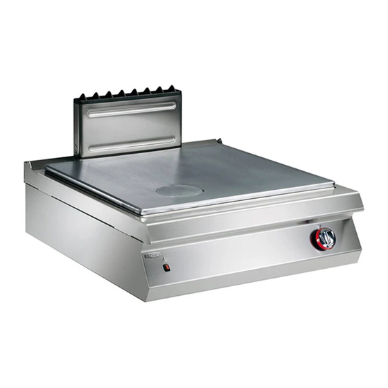
In funzione delle esigenze di utilizzo, l'apparecchia- chiatura, è stata progettata e costruita per la prepa- tura è prodotta in più versioni (vedi figura). razione e cottura di alimenti nell'ambito della ristorazione professionale. 291 TPCG 10 kW 7 kW 191TPG 190TP0 IDM-39614800100.tif - 5 - Italiano... - Page 8 Organi principali A)Piano di cottura: realizzato in acciaio inox. B)Bruciatori di piano: realizzati in ghisa smaltata, possono fornire potenze variabili in funzione della loro dimensione (solo per versione 291TPCG). C)Scarico fumi (tipo A): per evacuare i fumi generati dal bruciatore del forno e/o della piastra. D)Pulsante accensione: per accendere i bruciatori della piastra e del forno.
- Page 9 SEGNALI DI SICUREZZA E INFORMAZIONE L'illustrazione indica la posizione dei segnali applicati. A)Targa identificazione costruttore e apparec- chiatura. B)Pericolo generico: prima di effettuare qualsiasi tipo di intervento, leggere attentamente il manuale. C)Pericolo generico: durante il lavaggio dell'appa- recchiatura non dirigere getti d'acqua in pressio- ne sulle parti interne.
-
Page 10: Sicurezza
SICUREZZA NORME PER LA SICUREZZA Il costruttore, in fase di progettazione e costruzione, cità devono essere eseguiti esclusivamente da per- ha posto particolare attenzione agli aspetti che pos- sonale qualificato, con esperienza riconosciuta e sono provocare rischi alla sicurezza e alla salute acquisita nel settore specifico di intervento. -
Page 11: Uso E Funzionamento
USO E FUNZIONAMENTO RACCOMANDAZIONI PER L’USO Importante L'incidenza degli infortuni derivanti cipali. Attuare solo gli usi previsti dal co- dall'uso di apparecchiature dipende da struttore manomettere nessun molti fattori che non sempre si riescono a dispositivo per ottenere prestazioni diverse prevenire e controllare. - Page 12 ACCENSIONE E SPEGNIMENTO BRUCIATORE PIASTRA Accensione Importante Alla prima accensione lavare la piastra per togliere il grasso protettivo ed ogni even- tuale impurità, quindi accendere l'apparec- chiatura ed effettuare un preriscaldamento di circa 1 ora alla potenza minima. 1 - Aprire il rubinetto alimentazione gas. 2 - Premere e ruotare la manopola (B) in senso an- tiorario (pos.
- Page 13 ACCENSIONE E SPEGNIMENTO BRUCIATORI DI PIANO Accensione 1 - Aprire il rubinetto alimentazione gas. 2 - Premere e ruotare la manopola (A) in senso an- tiorario (pos. 1) ed accendere la spia pilota. 3 - Mantenere premuta la manopola per circa 15 sec per consentire l'intervento della termocop- pia.
-
Page 14: Manutenzioni
Spegnimento 2 - Ruotare la manopola in senso orario (pos. 4) 1 - Ruotare la manopola in senso orario per spegnere la spia pilota. (pos. 3) per spegnere il bruciatore. La spia pilo- 3 - Chiudere il rubinetto per garantire condizioni di ta rimarrà... - Page 15 Ogni 100 ore di esercizio fare eseguire, da operatori – verificare efficienza impianto elettrico; esperti e autorizzati, le seguenti operazioni: – eseguire l'ingrassaggio del rubinetto gas (vedi – controllo pressione gas e tenuta impianto; pag. 26). – verifica efficienza termocoppia di sicurezza; –...
- Page 16 PULIZIA PIANO DI COTTURA, BRUCIATORI E ACCESSORI Per questa operazione procedere nel modo indicato. 1 - Smontare lo spartifiamma (A) e il bruciatore (B). 2 - Pulire accuratamente il bruciatore e lo sparti- fiamma e verificare che i suoi fori non siano ostruiti.
-
Page 17: Guasti
CONTROLLO PRESSIONE GAS Per questa operazione procedere nel modo indicato. 1 - Chiudere il rubinetto alimentazione gas. 2 - Sfilare le manopole (A). 3 - Svitare le viti (C) e smontare il cruscotto (B). 4 - Svitare la vite (D) della presa di pressione. 5 - Collegare il manometro (E) alla presa di pres- sione (F). -
Page 18: Movimentazione E Installazione
MOVIMENTAZIONE E INSTALLAZIONE RACCOMANDAZIONI PER LA MOVIMENTAZIONE E INSTALLAZIONE Importante Eseguire la movimentazione e l'installazio- ste operazioni dovrà, se necessario, orga- ne nel rispetto delle informazioni fornite dal nizzare “piano sicurezza” costruttore e riportate direttamente sull'im- salvaguardare l'incolumità delle persone ballo, sull'apparecchiatura e nelle istruzioni direttamente coinvolte. - Page 19 MOVIMENTAZIONE E SOLLEVAMENTO L'apparecchiatura può essere movimentata con un dispositivo di sollevamento a forche o a gancio di portata adeguata. Prima di effettuare questa opera- zione, controllare la posizione del baricentro del ca- rico. Importante Nell'inserire il dispositivo di sollevamento, fare attenzione al tubo di alimentazione gas.
- Page 20 VENTILAZIONE LOCALE Nel locale dove è installata l'apparecchiatura, devo- no essere presenti delle prese d'aria per garantire il corretto funzionamento dell'apparecchiatura e per il ricambio d'aria del locale stesso. Le prese d'aria devono avere dimensioni adeguate, devono essere protette da griglie e collocate in modo da non poter essere ostruite.
- Page 21 MONTAGGIO APPARECCHIATURE IN BATTERIA Per montare le apparecchiature in batteria (fianco a fianco) procedere nel modo indicato. 1 - Sfilare le manopole (A). 2 - Svitare le viti (C) e smontare i cruscotti (B). 3 - Applicare, sui bordi da accostare, del nastro adesivo di protezione.
- Page 22 ALLACCIAMENTO GAS Importante Chi è autorizzato ad effettuare tale operazio- ne deve possedere capacità ed esperienza acquisita e riconosciuta nel settore specifico, dovrà eseguire l'allacciamento a regola d'arte e tenere conto di tutti i requisiti normativi e le- gislativi. Ad allacciamento completato, prima di rendere operativa l'attrezzatura, si dovrà...
- Page 23 ALLACCIAMENTO ELETTRICO Effettuare l'allacciamento dell'apparecchiatura alla Importante rete di alimentazione nel modo indicato. L'allacciamento deve essere effettuato da 1 - Installare, se non è presente, un interruttore se- personale autorizzato e qualificato, nel ri- zionatore (A) vicino all'apparecchiatura con spetto delle leggi vigenti in materia e con sganciatore magnetotermico e blocco differen- l'utilizzo di materiale appropriato e prescrit- ziale.
- Page 24 TRASFORMAZIONE ALIMENTAZIONE L'apparecchiatura è stata collaudata dal costruttore con il proprio gas di rete, segnalato dall’adesivo ap- plicato sulla targhetta di identificazione. Se il tipo di gas da allacciare è diverso da quello di collaudo, procedere nel modo indicato. 1 - Chiudere il rubinetto alimentazione gas (A). 2 - Sostituire l'ugello del bruciatore della piastra (vedi pag.
-
Page 25: Regolazioni
REGOLAZIONI RACCOMANDAZIONI PER LE REGOLAZIONI Importante Prima di effettuare qualsiasi tipo di regola- chiudere il rubinetto alimentazione gas ed zione, attivare tutti i dispositivi di sicurezza impedire l’accesso a tutti i dispositivi che previsti e valutare se sia necessario infor- potrebbero, se attivati, provocare condizio- mare adeguatamente il personale che ope- ni di pericolo inatteso causando danni alla... - Page 26 REGOLAZIONE MINIMO RUBINETTO VALVOLATO GAS (BRUCIATORI DI PIANO) Importante Questa regolazione si effettua solo se il tipo necessario verificare che la pressione del di gas da allacciare è diverso da quello di gas di alimentazione sia conforme al valore collaudo, dopo avere eseguito la trasforma- della pressione nominale relativa allo stes- zione dell’alimentazione (vedi pag.
- Page 27 REGOLAZIONE ARIA PRIMARIA BRUCIATORE FORNO Per questa operazione procedere nel modo indica- 1 - Chiudere il rubinetto alimentazione gas. 2 - Svitare le viti (B) e smontare il cruscotto (A). 3 - Allentare la vite di bloccaggio (C). 4 - Posizionare la boccola (D) in battuta, alla di- stanza riportata in figura.
-
Page 28: Sostituzione Parti
INGRASSAGGIO RUBINETTO GAS Per questa operazione procedere nel modo indicato. 1 - Chiudere il rubinetto alimentazione gas. 2 - Sfilare le manopole (A). 3 - Svitare le viti (C) e smontare il cruscotto (B). 4 - Svitare le viti (D) ed estrarre la calotta (E). 5 - Sfilare il cono (F). - Page 29 SOSTITUZIONE UGELLO BRUCIATORE DI PIANO (Ø 110 - 7 KW) Per questa operazione pro- cedere nel modo indicato. 1 - Chiudere il rubinetto ali- mentazione gas. 2 - Asportare la griglia (A). 3 - Sfilare il bruciatore (B). 4 - Svitare l'ugello (C) e so- stituirlo con quello adatto al tipo di gas utilizzato (vedi tabella in fondo al...
- Page 30 SOSTITUZIONE UGELLO SPIA PILOTA BRUCIATORE PIASTRA Per questa operazione procedere nel modo indica- 1 - Chiudere il rubinetto alimentazione gas. 2 - Sfilare le manopole (A). 3 - Svitare le viti (C) e smontare il cruscotto (B). 4 - Svitare il raccordo (D). 5 - Estrarre l'ugello (E) e sostituirlo con quello adatto al tipo di gas utilizzato (vedi tabella in fondo al manuale).
- Page 31 SOSTITUZIONE BOCCOLA ARIA BRUCIATORE FORNO Per questa operazione procedere nel modo indica- 1 - Chiudere il rubinetto alimentazione gas. 2 - Svitare le viti (B) e smontare il cruscotto (A). 3 - Allentare la vite (C). 4 - Estrarre la boccola (D) e sostituirla con quella adatta al tipo di gas utilizzato (vedi tabella in fondo al manuale).
- Page 33 CONTENTS ref. chapters page 1 GENERAL INFORMATION ..........3 2 TECHNICAL INFORMATION ..........5 3 SAFETY ................8 PART 4 USE AND OPERATION ............. 9 5 SERVICING ..............12 6 FAULT ................15 7 HANDLING AND INSTALLATION ........16 8 ADJUSTMENTS ............... 23 PART 9 REPLACING PARTS ............
- Page 34 Safety, regulations for, 8 Top burner nozzle (Ø130 - 10 kw), re- Top burner, primary air (7kw) adjust- Service, procedure for requesting, 4 placement, 27 ment, 25 Servicing, recommendations for, 12 Top burner pilot light, nozzle replace- Top burner, replacing pilot light noz- Switching the oven on and off, 11 ment, 28 zle, 28...
-
Page 35: General Information
GENERAL INFORMATION INFORMATION FOR THE READER To find the specific topics of interest to you quickly, 2nd part: contains all the information neces- refer to the index at the start of the manual. sary for special categories of reader, i.e. all This manual is subdivided into two parts. - Page 36 IDENTIFICATION OF CONSTRUCTOR AND APPLIANCE ) Gas consumption The nameplate shown here is fitted directly to the ) Testing gas indicator frame appliance. It contains references and all essential ) Voltage (V) information for operating safety. ) Frequency (Hz) Extra nameplate ) Electricity power consumption (W) ) Country of use ) Test voltage indicator...
-
Page 37: Technical Information
The appliance is produced in several versions to appliance, is designed and constructed for prepar- meet varying user requirements (see diagram). ing and cooking foods in the professional catering sector. 291 TPCG 10 kW 7 kW 191TPG 190TP0 IDM-39614800100.tif - 5 - English... - Page 38 Main Parts A)Hob: in stainless steel. B)Top burners: in enamelled cast iron, the power they are able to supply varies depending on their size (For version 291TPCG only). C)Fume exhaust vent (type A): for removal of the fumes generated by the oven and/or plate burner. D)Ignition button: lights the plate and oven burners.
- Page 39 SAFETY AND INFORMATION SIGNS The illustration shows the position of the signs pro- vided. A)Nameplate with manufacturer and appliance data. B)General hazard: read the manual carefully before carrying out any procedure. C)General hazard: when washing the appliance do not point pressurised water jets at internal parts. D)General hazard: all relevant regulations must be complied with.
-
Page 40: Safety
SAFETY SAFETY REGULATIONS During design and construction, the constructor has knowledge or skills must only be carried out by paid special attention to factors which may cause qualified staff with recognised experience in the risks to the health and safety of the people interact- specific sector. -
Page 41: Use And Operation
USE AND OPERATION RECOMMENDATIONS FOR USE Important The rate of accidents deriving from the use and the main functions. Use only as intend- of appliances depends on many factors ed by the constructor and never tamper which cannot always be foreseen and con- with any device to obtain performance lev- trolled. - Page 42 SWITCHING THE PLATE BURNER ON AND OFF Lighting Important The first time the griddle is switched on, wash the plate to remove the protective grease and any dirt, then switch on the ap- pliance and preheat it for about 1 hour at the minimum power setting.
- Page 43 SWITCHING THE TOP BURNER ON AND OFF Lighting 1 - Turn on the gas supply tap. 2 - Press the knob (A) and turn it anti-clockwise (pos. 1) to light the pilot light. 3 - Keep the knob pressed for about 15 sec. to prime the thermocouple.
-
Page 44: Servicing
Turning off 2 - Turn the knob clockwise (pos. 4) to turn off the 1 - Turn the knob clockwise (pos. 3) to turn the pilot light. burner off. The pilot light will remain on to allow 3 - Turn off the knob to ensure safety. the burner to be re-lit. - Page 45 Every 100 working hours have skilled, authorised – A check on the efficiency of the flues, cleaning personnel carry out the following operations. them if necessary – A check on the gas pressure and system tight- – check that the electrical system is in good work- ness ing order –...
- Page 46 CLEANING THE HOB, BURNERS AND ACCESSORIES To carry out this operation, proceed as follows. 1 - Remove the burner cap (A) and the burner (B). 2 - Clean the burner and the flame cap thoroughly and check that the holes in it are not blocked. 3 - Clean the ignition slot in the burner regularly.
-
Page 47: Fault
CHECKING GAS PRESSURE To carry out this operation, proceed as follows. 1 - Turn off the gas supply tap. 2 - Pull off the knob (A). 3 - Undo the screws (C) and remove the control panel (B). 4 - Undo the screw (D) of the pressure connection. 5 - Connect the pressure gauge (E) to the pressure test point (F). -
Page 48: Handling And Installation
HANDLING AND INSTALLATION RECOMMENDATIONS FOR HANDLING AND INSTALLATION Important When handling and installing the appliance use. If necessary, the person authorised to comply with the information provided by carry out these operations must organise a the constructor directly on the packaging, "safety plan"... - Page 49 HANDLING AND LIFTING The appliance can be handled using fork-lift or hook equipment of suitable load-carrying capacity. Before lifting, check the position of the load's centre of gravity. Important When engaging with the lifting equipment, watch out for the gas supply pipe. IDM-39610800600.tif INSTALLATION OF THE APPLIANCE All installation stages must be considered right from...
- Page 50 ROOM VENTILATION The room where the appliance is installed must have air inlets to ensure that the appliance can op- erate correctly and provide the necessary air ex- change in the room itself. The air inlets must be of appropriate size and must be protected by gratings and placed so that they cannot be obstructed.
- Page 51 ASSEMBLY APPLIANCES IN BANKS To assemble appliances in banks (side by side) proceed as described below. 1 - Pull off the knob (A). 2 - Undo the screws (C) and remove the control panels (B). 3 - Apply masking tape to the edges to be placed side by side.
- Page 52 GAS CONNECTION Important Those authorised to carry out this opera- tion must have experience acquired and certified in the specific sector, must make the connection to the proper standards, and must comply with all the relevant regu- lations and legislation. Once the connec- tion has been made, before the appliance is put into operation a general check must be made to ensure there are no gas leaks.
- Page 53 ELECTRICAL CONNECTION Connect the appliance to the mains electricity sup- Important ply as follows. The connection must be made by author- 1 - If not already present, install a circuit-breaker ised, skilled personnel, in accordance with (A) with overload cutout and differential safety the relevant legal requirements, using ap- breaker close to the appliance.
- Page 54 CONVERSION OF GAS SUPPLY The constructor has tested the appliance with its own mains gas, identified by the sticker applied to the nameplate. If the type of gas to be connected is different from that used for testing, proceed as follows. 1 - Turn off the gas supply tap.
-
Page 55: Adjustments
ADJUSTMENTS RECOMMENDATIONS FOR ADJUSTMENTS Important Before making any type of adjustment, acti- turn off the gas supply tap and prevent ac- vate all the safety devices provided and de- cess to all devices which might cause un- cide whether staff at work and those in the expected health and safety hazards if vicinity should be informed. - Page 56 ADJUSTING GAS CONTROL VALVE MINIMUM SETTING (TOP BURNERS) Important This adjustment is only required if the type fore making this adjustment, check that the of gas to be connected is different from that gas supply pressure is the same as the rat- used for testing after the conversion proce- ed pressure for the type of gas in use (see dure has been carried out (see page 22).
- Page 57 ADJUSTING OVEN BURNER PRIMARY AIR To carry out this operation, proceed as follows. 1 - Turn off the gas supply tap. 2 - Undo the screws (B) and remove the control panel (A). 3 - Undo the locking screw (C). 4 - Set the bush (D) in contact at the distance shown in the figure.
-
Page 58: Replacing Parts
GREASING THE GAS TAP To carry out this operation, proceed as follows. 1 - Turn off the gas supply tap. 2 - Pull off the knob (A). 3 - Undo the screws (C) and remove the control panel (B). 4 - Undo the screws (D) and extract the cap (E). 5 - Pull off the cone (F). - Page 59 REPLACING THE TOP BURNER NOZZLE (Ø110 - 7 KW) To carry out this operation, proceed as follows. 1 - Turn off the gas supply tap. 2 - Remove the grid (A). 3 - Extract the burner (B). 4 - Unscrew the nozzle (C) and replace it with the one suitable for the type of gas in use (see...
- Page 60 REPLACING THE PLATE BURNER PILOT LIGHT NOZZLE To carry out this operation, proceed as follows. 1 - Turn off the gas supply tap. 2 - Pull off the knob (A). 3 - Undo the screws (C) and remove the control panel (B).
- Page 61 REPLACING OVEN BURNER AIR BUSHING To carry out this operation, proceed as follows. 1 - Turn off the gas supply tap. 2 - Undo the screws (B) and remove the control panel (A). 3 - Undo the screw (C). 4 - Extract the bushing (D) and replace it with the one suitable for the type of gas in use (see table at back of manual).
- Page 63 INHALTSVERZEICHNIS Ref. Kapitel Seite 1 ALLGEMEINES ..............3 2 TECHNISCHE INFORMATIONEN ........5 3 SICHERHEIT ..............8 1. TEIL 4 GEBRAUCH UND BETRIEB ..........9 5 WARTUNG ............... 12 6 DEFEKTE ................. 15 7 HANDHABUNG UND INSTALLATION ......16 8 EINSTELLUNGEN ............23 2.
- Page 64 Kochstellenbrenner, Ein- und Aus- Primärluft des Kochstellenbrenners Technische Daten, 6 schalten, 11 (7 kw), Einstellung, 25 Testlauf zur Abnahme des Geräts, 22 Kontrolle des Gasdrucks, 15 Raumbelüftung, 18 Tipps für den Gebrauch, 12 Kundendienst anfordern, 4 Reinigung der Kochmulde, Brenner Transport, 16 Längerer Stillstand des Geräts, 12 und Zubehörteile, 14...
-
Page 65: Allgemeines
ALLGEMEINES INFORMATIONEN FÜR DEN LESER Konsultieren Sie das Sachregister, das am Anfang 2. Teil: Diese Informationen wenden sich an des Handbuchs zu finden ist, um leichter unter be- eine bestimmte Zielgruppe. Sie sind für er- stimmten Themen von besonderem Interesse fahrene Bediener bestimmt, die für Handha- nachschlagen zu können. - Page 66 TYPENSCHILD FÜR HERSTELLER UND GERÄT ) Gasverbrauch Das abgebildete Typenschild wird direkt auf dem ) Testgasanzeige Gerät aufgebracht. Es enthält sämtliche Angaben ) Spannung (V) und Hinweise, die für den sicheren Betrieb unerläs- ) Frequenz (Hz) slich sind. ) Leistungsaufnahme (W) Ergänzungsschild ) Abnahmespannungsanzeige ) Benutzerland...
-
Page 67: Technische Informationen
Die Bratplatte, die im Folgenden als Gerät bezeich- Das Gerät wird bedarfsabhängig in verschiedenen net wird, wurde zum Zubereiten und Garen von Versionen hergestellt (siehe Abbildung). Speisen in Restaurantbetrieben projektiert und konstruiert. 291 TPCG 10 kW 7 kW 191TPG 190TP0 IDM-39614800100.tif - 5 - Deutsch... - Page 68 Hauptorgane A)Kochmulde: aus Edelstahl. B)Kochstellenbrenner: aus emailliertem Gusseisen, Heizleistung von Größe abhängig (Nur bei Version 291TPCG). C)Rauchabzug (Typ A): zum Abführen der vom Bren- ner des Backofens und/oder der Bratplatte erzeug- ten Rauchgase. D)Taste Zündung: zum Zündern der Brenner der Bratplatte und des Backofens.
- Page 69 SICHERHEITSHINWEISE UND INFORMATIONEN Die Abbildung zeigt die Anordnung der aufgekleb- ten Sicherheitshinweise. A)Typenschild mit Angabe des Herstellers und der Gerätekenndaten. B)Allgemeine Gefahr: Vor Ausführung irgendeines Eingriffs zuerst das Handbuch aufmerksam lesen. C)Allgemeine Gefahr: Beim Waschen des Geräts den Wasserstrahl nicht direkt auf die inneren Teile richten.
-
Page 70: Sicherheit
SICHERHEIT SICHERHEITSVORSCHRIFTEN Der Hersteller hat bei Entwicklung und Fertigung dürfen ausschließlich von qualifiziertem Personal dieses Produkts besondere Sorgfalt auf Aspekte mit nachweislicher Erfahrung in diesem speziellen verwendet, die eine Gefahr für die Sicherheit und Gebiet des Eingriffs durchgeführt werden. die Gesundheit der Personen, die dieses Gerät Aus hygienischen Gründen und zum Schutz vor handhaben, hervorrufen können. -
Page 71: Gebrauch Und Betrieb
GEBRAUCH UND BETRIEB EMPFEHLUNGEN FÜR DEN GEBRAUCH Wichtig Das Auftreten von Unfällen bei der Verwen- schränken Sie sich auf die vom Hersteller dung von Geräten hängt von vielen Faktoren vorgesehenen Verwendungszwecke, ohne ab, die nicht immer zu vermeiden und zu Änderungen an den Vorrichtungen vorzu- steuern sind. - Page 72 EIN- UND AUSSCHALTEN DES BRATPLATTENBRENNERS Zündung Wichtig Bei der ersten Einschaltung die Platte säu- bern, um den schützenden Fettfilm und eventuelle Verunreinigungen zu entfernen; dann das Gerät einschalten und ca. 1 Stun- de auf Mindestleistungsstufe vorheizen. 1 - Öffnen Sie den Gashahn. 2 - Schalter (B) niederdrücken und entgegen dem Uhrzeigersinn drehen (Pos.
- Page 73 EIN- UND AUSSCHALTEN DER KOCHSTELLENBRENNER Zündung 1 - Öffnen Sie den Gashahn. 2 - Den Schalter (A) niederdrücken und entgegen dem Uhrzeigersinn drehen (Pos. 1) und die Zündflamme zünden. 3 - Halten Sie den Bedienknebel etwa 15 Sekun- den lang gedrückt, damit das Thermoelement in Aktion treten kann.
-
Page 74: Wartung
Abschaltung 2 - Drehen Sie den Bedienknebel im Uhrzeigersinn 1 - Drehen Sie den Bedienknebel im Uhrzeigersinn (Pos. 4), um den Zündflammenbrenner auszu- (Pos. 3), um den Brenner abzuschalten. Der schalten. Zündflammenbrenner bleibt für die folgenden 3 - Drehen Sie den Gashahn ab, um die Sicher- Zündungen des Brenners eingeschaltet. - Page 75 Nach jeweils 100 Betriebsstunden müssen fol- – Überprüfung der Funktionsfähigkeit und, bei Be- gende Arbeiten von erfahrenen und autorisierten darf, Reinigung des Abzugsrohrs Bedienern ausgeführt werden: – Funktionstüchtigkeit der Stromanlage prüfen – Kontrolle des Gasdrucks und der Dichtigkeit der – Schmierung des Gashahns (siehe S. 26). Anlage –...
- Page 76 REINIGUNG DER KOCHMULDE, BRENNER UND ZUBEHÖRTEILE Für diesen Vorgang in der angegebenen Weise verfahren. 1 - Brennerdeckel (A) und Brenner (B) ausbauen. 2 - Den Brenner und den Brennerdeckel gründlich reinigen und sicherstellen, dass die Löcher des Brennerdeckels nicht verstopft sind. 3 - Regelmäßig das Zündloch im Brenner reinigen.
-
Page 77: Defekte
KONTROLLE DES GASDRUCKS Für diesen Vorgang in der angegebenen Weise verfahren. 1 - Schließen Sie den Gaszufuhrhahn 2 - Den Schalter (A) abziehen. 3 - Drehen Sie die Schrauben (C) heraus und montieren Sie die Blende (B) ab. 4 - Drehen Sie die Schrauben (D) aus dem Druck- prüfpunkt. -
Page 78: Handhabung Und Installation
HANDHABUNG UND INSTALLATION EMPFEHLUNGEN FÜR DIE INSTALLATION UND HANDHABUNG Wichtig Beachten Sie die Hinweise des Herstellers, nen autorisierte Person wird bei Bedarf die direkt auf der Verpackung, auf dem Ge- einen „Sicherheitsplan" aufstellen müssen, rät selbst oder in der Gebrauchsanweisung um die Unversehrtheit der direkt an dem zu finden sind, wenn Sie das Gerät handha- Vorgang beteiligten Personen zu gewähr-... - Page 79 HANDHABUNG UND HUB Das Gerät kann mit einem Hubmittel bewegt wer- den, das mit Gabeln oder Haken ausgestattet ist und die geeignete Traglast besitzt. Vor diesem Vorgang ist der Schwerpunkt der Last zu überprüfen. Wichtig Achten Sie beim Einsatz des Hubmittels auf das Gaszufuhrrohr.
- Page 80 RAUMBELÜFTUNG Der Raum, in dem das Gerät installiert wird, muss über Zuluftöffnungen verfügen, um den einwand- freien Betrieb des Geräts und den Luftaustausch im Raum selbst zu gewährleisten. Die Zuluftöffnungen müssen ausreichend groß be- messen und durch Gitter geschützt und so positio- niert sein, dass sie nicht verdeckt werden können.
- Page 81 MONTAGE BEI REIHENAUFSTELLUNG Verfahren Sie folgendermaßen, um Geräte (neben- einander) in einer Reihe aufzustellen. 1 - Den Schalter (A) abziehen. 2 - Die Schrauben (C) ausschrauben und die Blen- den (B) ausbauen. 3 - Bekleben Sie die Gerätekanten, die nebenein- ander angeordnet werden sollen, mit einem Schutzband.
- Page 82 GASANSCHLUSS Wichtig Diese Arbeit darf nur von zugelassenen und erfahrenen Fachleuten ausgeführt wer- den. Der Anschluss muss fachgerecht und vorschriftsmäßig ausgeführt werden und allen einschlägigen gesetzlichen Bestim- mungen entsprechen. Nach Ausführung des Anschlusses muss vor der Inbetrieb- nahme des Geräts durch eine allgemeine Kontrolle sichergestellt werden, dass nir- gends Gas austritt.
- Page 83 STROMANSCHLUSS Den Anschluss des Geräts an das Stromnetz in der angegebenen Weise ausführen. Wichtig 1 - Falls nicht schon vorhanden, einen Trennschal- Der Anschluss muss von autorisiertem ter (A) mit thermomagnetischem Auslöser und Fachpersonal in Einklang mit den einschlä- FI-Block in der Nähe des Geräts installieren. gigen gesetzlichen Bestimmungen und un- 2 - Den Schalter (B) abziehen.
- Page 84 UMSTELLUNG DER GASVERSORGUNG Der werkseitig durchgeführte Testlauf ist mit dem Gas- typ des örtlichen Gaswerks durchgeführt worden. Der Gastyp des Testlaufs ist aus dem Aufkleber ersichtlich, der auf dem Typenschild angebracht wurde. Falls Sie das Gerät an eine Gaszufuhr anderen Typs anschließen müssen, gehen Sie folgender- maßen vor: 1 - Schließen Sie den Gaszufuhrhahn...
-
Page 85: Einstellungen
EINSTELLUNGEN EMPFEHLUNGEN FÜR DIE EINSTELLUNGEN Wichtig Vor jeder Regulierung an den Einstellungen den Gashahn ab und verhindern Sie den müssen sämtliche vorgesehenen Sicher- Zugang zu allen Vorrichtungen, die bei ih- heitsvorrichtungen aktiviert werden. Über- rer Aktivierung eine unvorgesehene Gefahr legen Sie, ob es notwendig ist, das hervorrufen und Schäden für die Sicherheit arbeitende Personal und die in der Nähe be- und die Gesundheit von Personen verursa-... - Page 86 EINSTELLUNG DER KLEINSTELLUNG BEIM VOLLGESICHERTEN GASVENTIL (KOCHSTELLENBRENNER) Wichtig Diese Einstellung muss nur ausgeführt man sicherstellen, dass der Druck im Gas- werden, wenn die anzuschließende Gasart netz dem für die jeweilige Gasart vorge- von der Prüfgasart verschieden ist, d.h. schriebenen Nenndruck entspricht (siehe also im Anschluss an eine Gasumstellung die Tabelle am Ende des Handbuchs).
- Page 87 EINSTELLUNG DER PRIMÄRLUFT DES BACKOFENBRENNERS Für diesen Vorgang in der angegebenen Weise verfahren. 1 - Schließen Sie den Gaszufuhrhahn 2 - Drehen Sie die Schrauben (B) heraus und montieren Sie die Blende (A) ab. 3 - Die Klemmschraube (C) lockern. 4 - Die Buchse (D) auf dem in der Abbildung ange- gebenen Abstand am Anschlag positionieren.
-
Page 88: Austausch Von Bauteile
SCHMIERUNG DES GASHAHNS Für diesen Vorgang in der angegebenen Weise verfahren. 1 - Schließen Sie den Gaszufuhrhahn 2 - Den Schalter (A) abziehen. 3 - Drehen Sie die Schrauben (C) heraus und montieren Sie die Blende (B) ab. 4 - Drehen Sie die Schrauben (D) heraus und neh- men Sie die Haube (E) heraus. - Page 89 AUSTAUSCH DER DÜSE DES KOCHSTELLENBRENNERS (Ø110 - 7 KW) Für diesen Vorgang in der angegebenen Weise verfah- ren. 1 - Schließen Sie den Gas- zufuhrhahn 2 - Den Topfträgerrost (A) entfernen. 3 - Den Brenner (B) heraus- ziehen. 4 - Schrauben Sie die Düse (C) heraus und ersetzen Sie sie mit dem für den betreffenden Gastyp ge-...
- Page 90 AUSTAUSCH DER DÜSE DES ZÜNDFLAMMENBRENNERS DES BRATPLATTENBRENNERS Für diesen Vorgang in der angegebenen Weise verfahren. 1 - Schließen Sie den Gaszufuhrhahn 2 - Den Schalter (A) abziehen. 3 - Drehen Sie die Schrauben (C) heraus und montieren Sie die Blende (B) ab. 4 - Drehen Sie das Verbindungsstück (D) heraus.
- Page 91 AUSTAUSCH DER LUFTDÜSE DES BACKOFENBRENNERS Für diesen Vorgang in der angegebenen Weise verfahren. 1 - Schließen Sie den Gaszufuhrhahn 2 - Drehen Sie die Schrauben (B) heraus und montieren Sie die Blende (A) ab. 3 - Die Schraube (C) lockern. 4 - Die Düse (D) herausziehen und durch die für die Gasart geeignete Düse ersetzen (siehe die Tabelle am Ende des Handbuchs).
- Page 93 INDEX réf. chapitres page 1 INFORMATIONS GENERALES ......... 3 2 INFORMATIONS TECHNIQUES ........5 3 SÉCURITÉ ................. 8 PARTIE 4 UTILISATION ET FONCTIONNEMENT ......9 5 ENTRETIEN ..............12 6 PANNES ................15 7 MANUTENTION ET INSTALLATION ....... 16 8 RÉGLAGES ..............23 PARTIE 9 REMPLACEMENT DE PIÈCES ........
- Page 94 Réglage du minimum du robinet gaz Remplacement de la buse du brûleur sécurité et information, signaux de, 7 de sécurité (brûleurs fourneau), 24 fourneau (Ø130 - 10 kW), 27 sécurité, dispositifs de, 6 Réglage du minimum du robinet gaz Remplacement de la buse veilleuse Sécurité, normes de, 8 de sécurité...
- Page 95 INFORMATIONS GENERALES INFORMATIONS POUR LE LECTEUR Pour retrouver facilement les sujets qui vous inté- 2e partie: elle contient toutes les informa- ressent, consulter l’index analytique au début du tions nécessaires aux destinataires homogè- manuel. nes, c’est-à-dire tous les opérateurs experts Ce manuel est divisé...
- Page 96 IDENTIFICATION DU FABRICANT ET DE L’APPAREIL ) Puissance déclarée (kW) La plaque d’identification représentée, est appli- ) Consommation de gaz quée directement sur l'appareil. Elle reporte les ré- ) Indicateur du gaz d’essai férences et les indications indispensables à la ) Tension (V) sécurité.
- Page 97 été conçue et fabriquée pour la pré- est réalisé en plusieurs versions (voir figure). paration et la cuisson d'aliments dans le domaine de la restauration professionnelle. 291 TPCG 10 kW 7 kW 191TPG 190TP0 IDM-39614800100.tif - 5 - Français...
- Page 98 Organes principaux A)Plan de travail: en acier inox. B)Brûleurs fourneau: en fonte émaillée, ils peuvent fournir des puissances variables en fonction de leur dimension (Seulement pour la version 291TPCG). C)Évacuation des fumées (type (A): pour évacuer les fumées générées par le brûleur de four et/ou de la plaque.
- Page 99 SIGNAUX DE SÉCURITÉ ET INFORMATION L’illustration indique la position des signaux appli- qués. A)Plaque d'identification du fabricant et de l'ap- pareil. B)Danger générique: avant tout type d’intervention, lire attentivement ce manuel. C)Risque générique: pendant le lavage de l’appareil ne pas diriger de jets d’eau sous pression sur les piè- ces intérieures.
- Page 100 SÉCURITÉ NORMES DE SÉCURITÉ Le fabricant, lors de la conception et de la fabrica- ne peuvent être exécutés que par du personnel tion, a fait très attention aux aspects qui peuvent qualifié, ayant une expérience reconnue et acquise provoquer des risques à la sécurité et à la santé des dans le secteur spécifique d’intervention.
- Page 101 UTILISATION ET FONCTIONNEMENT RECOMMANDATIONS POUR L'UTILISATION Important L’incidence des accidents dérivant de l’uti- les. Utiliser seulement comme prévu par le lisation d’appareils dépend de beaucoup de fabricant et ne modifier aucun dispositif facteurs que l’on ne peut pas toujours pré- pour obtenir des performances différentes venir et contrôler.
- Page 102 ALLUMAGE ET EXTINCTION DU BRÛLEUR DE LA PLAQUE Allumage Important Au premier allumage, laver la plaque pour enlever la graisse de protection et toute im- pureté éventuelle, puis allumer l'appareil et préchauffer pendant environ 1 heure à la puissance minimale. 1 - Ouvrir le robinet d’alimentation du gaz.
- Page 103 ALLUMAGE ET EXTINCTION BRÛLEURS FOURNEAU Allumage 1 - Ouvrir le robinet d’alimentation du gaz. 2 - Pousser et tourner la manette (A) en sens anti- horaire (pos. 1) pour allumer la veilleuse pilote. 3 - Continuer à appuyer sur la manette pendant environ 15 s pour permettre l’intervention du thermocouple.
- Page 104 Extinction 2 - Tourner la manette en sens horaire (pos. 4) pour éteindre la veilleuse pilote. 1 - Tourner la manette en sens horaire (pos. 3) 3 - Fermer le robinet pour garantir les conditions pour éteindre le brûleur. La veilleuse pilote res- de sécurité.
- Page 105 Tous les 100 heures de fonctionnement faire fai- – Vérification de l’efficacité de la mitre et son net- re, par des opérateurs experts et autorisés, les opé- toyage éventuel rations suivantes: – vérifier l'efficacité de l'installation électrique – Contrôle de la pression du gaz et de l’étanchéité –...
- Page 106 NETTOYAGE DE LA TABLE DE CUISSON, DES BRÛLEURS ET DES ACCESSOIRES Pour cette opération, procéder comme suit. 1 - Démonter la tête de brûleur (A) et le brûleur (B). 2 - Nettoyer soigneusement le brûleur et la tête de brûleur et vérifier que ses trous ne soient pas obstrués.
- Page 107 CONTRÔLE DE LA PRESSION DU GAZ Pour cette opération, procéder comme suit. 1 - Fermer le robinet d’alimentation du gaz. 2 - Enlever la manette (A). 3 - Dévisser les vis (C) et démonter le tableau de commandes (B). 4 - Dévisser la vis (D) de la prise de pression. 5 - Raccorder le manomètre (E) à...
- Page 108 MANUTENTION ET INSTALLATION RECOMMANDATIONS POUR LA MANUTENTION ET L’INSTALLATION Important Effectuer la manutention et l’installation en effectuer ces opérations devra, si nécessai- respectant les informations fournies par le re, organiser un « plan de sécurité » pour fabricant, reportées directement sur l’em- sauvegarder la sécurité...
- Page 109 MANUTENTION ET LEVAGE L'appareil peut être manutentionné avec un dispo- sitif de levage à fourches ou à crochet d’une capa- cité de charge appropriée. Avant d’effectuer cette opération, contrôler la posi- tion du centre de gravité de la charge. Important En introduisant le dispositif de levage, faire attention au tuyau d’alimentation du gaz.
- Page 110 VENTILATION DE LA PIÈCE Dans la pièce où l’appareil est installé, il doit y avoir des prises d’air pour garantir le fonctionnement cor- rect de l’appareil et pour le changement d’air dans la pièce même. Les prises d’air doivent avoir des dimensions adé- quates, être protégées par des grilles et placées de façon à...
- Page 111 MONTAGE DES APPAREILS EN BATTERIE Pour monter les appareils en batterie (les uns à côté des autres), procéder comme suit. 1 - Enlever la manette (A). 2 - Dévisser les vis (C) et démonter les tableaux de commandes (B). 3 - Appliquer, sur les bords à rapprocher, du ruban adhésif de protection.
- Page 112 RACCORDEMENT DU GAZ Important La personne autorisée à effectuer cette opération devra avoir les capacités et l’ex- périence acquise et reconnue dans le sec- teur spécifique ; elle devra effectuer le raccordement dans les règles de l’art et te- nir compte de toutes les exigences impo- sées par les normes et les lois.
- Page 113 BRANCHEMENT ÉLECTRIQUE Effectuer le branchement de l'appareil au réseau Important électrique d'alimentation comme suit. Le branchement doit être fait par du per- 1 - Installer, s’il n’est pas présent, un interrupteur sonnel autorisé et qualifié, conformément sectionneur (A) près de l’appareil avec déclen- aux lois en vigueur à...
- Page 114 TRANSFORMATION DE L’ALIMENTATION L'appareil a été essayé par le fabricant avec le gaz de réseau, signalé par l’adhésif collé sur la plaque d’identification. Si le type de gaz à raccorder est différent de celui d’essai, procéder comme suit. 1 - Fermer le robinet d’alimentation du gaz. 2 - Remplacer la buse du brûleur de la plaque (voir page 26).
- Page 115 RÉGLAGES RECOMMANDATIONS POUR LES RÉGLAGES Important Avant d’effectuer tout type de réglage, acti- empêcher l’accès à tous les dispositifs qui ver tous les dispositifs de sécurité prévus pourraient, s’ils sont activés, provoquer et évaluer s’il faut informer le personnel qui des conditions de danger inattendu en cau- travaille et celui à...
- Page 116 RÉGLAGE DU MINIMUM DU ROBINET GAZ DE SÉCURITÉ (BRÛLEURS FOURNEAU) Important Ce réglage n'est effectué que si le type de du gaz d'alimentation soit conforme à la va- gaz à raccorder est différent de celui d'es- leur de la pression nominale relative au sai et après avoir effectué...
- Page 117 RÉGLAGE AIR PRIMAIRE DU BRÛLEUR DE FOUR Pour cette opération, procéder comme suit. 1 - Fermer le robinet d’alimentation du gaz. 2 - Dévisser les vis (B) et démonter le tableau de commandes (A). 3 - Desserrer la vis de blocage (C). 4 - Placer la douille (D) en butée, à...
- Page 118 GRAISSAGE DU ROBINET À GAZ Pour cette opération, procéder comme suit. 1 - Fermer le robinet d’alimentation du gaz. 2 - Enlever la manette (A). 3 - Dévisser les vis (C) et démonter le tableau de commandes (B). 4 - Dévisser les vis (D) et extraire la calotte (E). 5 - Extraire le cône (F).
- Page 119 REMPLACEMENT DE LA BUSE DU BRÛLEUR FOURNEAU (Ø110 - 7 KW) Pour cette opération, procé- der comme suit. 1 - Fermer le robinet d’ali- mentation du gaz. 2 - Enlever la grille (A). 3 - Enlever le brûleur (B). 4 - Dévisser la buse (C) et la remplacer par celle adaptée au type de gaz utilisé...
- Page 120 REMPLACEMENT DE LA BUSE VEILLEUSE PILOTE BRÛLEUR DE LA PLAQUE Pour cette opération, procéder comme suit. 1 - Fermer le robinet d’alimentation du gaz. 2 - Enlever la manette (A). 3 - Dévisser les vis (C) et démonter le tableau de commandes (B).
- Page 121 REMPLACEMENT DE LA DOUILLE AIR DU BRÛLEUR DE FOUR Pour cette opération, procéder comme suit. 1 - Fermer le robinet d’alimentation du gaz. 2 - Dévisser les vis (B) et démonter le tableau de commandes (A). 3 - Desserrer les vis (C). 4 - Extraire la douille (D) et la remplacer par celle adaptée au type de gaz utilisé...
- Page 123 ÍNDICE ref. capítulos pág 1 INFORMACIONES DE CARÁCTER GENERAL ....3 2 INFORMACIONES DE CARÁCTER TÉCNICO ....5 3 SEGURIDAD ..............8 PARTE 4 USO Y FUNCIONAMIENTO ..........9 5 MANTENIMIENTO ............12 6 AVERÍAS ................15 7 DESPLAZAMIENTO E INSTALACIÓN ......16 8 REGULACIONES .............
- Page 124 Recomendaciones para efectuar las Regulación mínimo llave con válvula Sustitución inyector del quemador regulaciones, 23 de seguridad gas (quemadores del horno, 27 Recomendaciones para el desplaza- plano), 24 Sustitución inyector testigo piloto miento y la instalación, 16 Regulaciones, recomendaciones quemador de plano, 28 Regulación aire primario quemador para efectuar las, 23 Sustitución inyector testigo piloto...
-
Page 125: Informaciones De Carácter General
INFORMACIONES DE CARÁCTER GENERAL INFORMACIONES PREVIAS Para ubicar fácilmente los temas específicos de in- 2a parte: contiene todas las informaciones terés, consúltese el índice analítico que se encuen- necesarias para destinatarios homogéneos, tra al inicio del manual. esto es, todos los operadores expertos y au- Este manual comprende dos partes. - Page 126 IDENTIFICACIÓN FABRICANTE Y EQUIPO ) Consumo de gas La placa de identificación fijada directamente en el ) Indicador gas prueba de funcionamiento equipo reproduce todas las referencias e indicacio- ) Tensión (V) nes indispensables para la seguridad de servicio. ) Frecuencia (Hz) Placa complementaria ) Potencia eléctrica absorbida (W) ) País de uso...
-
Page 127: Informaciones De Carácter Técnico
(véa- para preparar y cocer alimentos en el sector de la se figura). restauración profesional. 291 TPCG 10 kW 7 kW 191TPG 190TP0 IDM-39614800100.tif - 5 - Español... - Page 128 Órganos principales A)Encimera: fabricada en acero inox. B)Quemadores de plano: realizados en fundición es- maltada, pueden proporcionar potencias variables en función de sus dimensiones (Sólo para versión 291TPCG). C)Descarga humos (tipo A): para evacuar los humos generados por el quemador del horno y/o de la plan- cha.
- Page 129 SEÑALIZACIONES DE SEGURIDAD E INFORMACIÓN La ilustración indica la posición de las señalizacio- nes fijadas en el equipo. A)Placa de identificación fabricante y aparato. B)Peligro genérico: antes de efectuar cualquier tipo de intervención leer atentamente el manual. C)Peligro genérico: durante el lavado del aparato no dirigir chorros de agua a presión hacia sus partes in- ternas.
-
Page 130: Seguridad
SEGURIDAD NORMAS DE SEGURIDAD Durante las fases de diseño y producción el fabri- una capacidad especial, deben ser efectuadas ex- cante ha prestado especial atención a los factores clusivamente por personal calificado y con expe- que pueden provocar riesgos en cuanto a seguri- riencia reconocida y adquirida en el sector dad y salud de las personas que interactúan con el específico de la intervención. -
Page 131: Uso Y Funcionamiento
USO Y FUNCIONAMIENTO RECOMENDACIONES DE USO Importante El porcentaje de accidentes derivados del Se deben ejecutar sólo operaciones pro- uso de equipos depende de muchos facto- pias de los usos previstos por el fabricante. res que no siempre se logran prevenir y No alterar los equipos con el fin de obtener controlar. - Page 132 ENCENDIDO Y APAGADO DEL QUEMADOR PLANCHA Encendido Importante Al efectuar el primer encendido lave la plancha a fin de eliminar la grasa protecto- ra y toda otra eventual impureza. A conti- nuación encienda el aparato y efectúe un precalentamiento de aproximadamente una hora con potencia mínima.
- Page 133 ENCENDIDO Y APAGADO QUEMADORES DE PLANO Encendido 1 - Abrir el grifo de alimentación del gas. 2 - Presionar y girar el mando (A) en sentido anti- horario (pos. 1) y encender el testigo piloto. 3 - Mantener presionado el mando durante aprox. 15 s para obtener la intervención del termopar.
-
Page 134: Mantenimiento
Apagado 2 - Para apagar el testigo piloto, girar el mando en el sentido de las agujas del reloj (pos. 4). 1 - Para apagar el quemador, girar el mando en el 3 - Cerrar el grifo a fin de garantizar condiciones sentido de las agujas del reloj (pos. - Page 135 Cada 100 horas de servicio, operadores expertos – Controlar la eficacia de la chimenea y eventual- y autorizados deben efectuar las siguientes opera- mente, efectuar una limpieza ciones. – Controlar de la eficiencia del sistema eléctrico – Controlar presión gas y hermeticidad del sistema –...
- Page 136 LIMPIEZA DE ENCIMERA, QUEMADORES Y ACCESORIOS Para efectuar esta operación, aplicar las siguientes instrucciones. 1 - Desmontar el casquete quemador (A) y el que- mador (B). 2 - Limpiar esmeradamente el quemador y el cas- quete quemador y verificar que los orificios no estén obstruidos.
-
Page 137: Averías
CONTROL DE LA PRESIÓN DEL GAS Para efectuar esta operación, aplicar las siguientes instrucciones. 1 - Cerrar el grifo de alimentación del gas. 2 - Retirar el mando (A). 3 - Desenroscar los tornillos (C) y desmontar el ta- blero de instrumentos (B). 4 - Desenroscar el tornillo (D) de la toma de pre- sión. -
Page 138: Desplazamiento E Instalación
DESPLAZAMIENTO E INSTALACIÓN RECOMENDACIONES PARA EL DESPLAZAMIENTO Y LA INSTALACIÓN Importante Efectuar el desplazamiento e instalación rizada para efectuar estas operaciones de- respetando las indicaciones proporciona- berá, si fuera necesario, organizar un "plan das por el fabricante, reproducidas directa- de seguridad", a fin de salvaguardar la in- mente sobre el embalaje, en el equipo y en columidad de las personas directamente las instrucciones de uso. - Page 139 DESPLAZAMIENTO Y ELEVACIÓN El equipo puede ser desplazado con un equipo de elevación de horquillas o de gancho, de capacidad adecuada. Para ejecutar esta operación se debe controlar atentamente el centro de gravedad de la carga. Importante Proceder con cautela al introducir el equipo de elevación a fin de no dañar el tubo de ali- mentación del gas.
- Page 140 VENTILACIÓN DEL AMBIENTE El ambiente destinado a la instalación, deberá dis- poner de tomas de aire adecuadas como para ga- rantizar el correcto funcionamiento del aparato y deberá ventilarse oportunamente para que cambie el aire dentro del mismo. Las tomas de aire deberán ser de tamaño adecua- do, estar protegidas por rejillas y colocadas de ma- nera que no se puedan tapar.
- Page 141 MONTAJE DE EQUIPOS EN BATERÍA Para montar los equipos en batería (uno al lado del otro) aplicar las siguientes instrucciones. 1 - Retirar el mando (A). 2 - Desenroscar los tornillos (C) y desmontar los paneles de mando (B). 3 - Poner cinta adhesiva de protección sobre los bordes a juntar.
- Page 142 ENLACE GAS Importante El personal autorizado para ejecutar esta operación debe poseer capacidad y haber adquirido experiencia efectiva en el sector específico; la conexión deberá ejecutarse respetando rigurosamente todos los requi- sitos establecidos por las normativas vi- gentes. Una vez efectuada la conexión, antes de poner en funcionamiento el apara- to se deberá...
- Page 143 CONEXIÓN ELÉCTRICA Conectar el aparato a la red eléctrica de alimenta- ción respetando las siguientes instrucciones. Importante 1 - En caso de no estar presente, instalar un inte- La conexión deberá asignarse al personal rruptor seccionador (A) en proximidad del apa- autorizado y experto, que deberá...
- Page 144 TRANSFORMACIÓN ALIMENTACIÓN El fabricante ha sometido el equipo a una prueba de funcionamiento con el gas de la red de su propio país, señalándolo con el adhesivo fijado en la placa de identificación. Si el tipo de gas a utilizar es diferente de aquél usa- do en la prueba de funcionamiento, aplicar las si- guientes instrucciones.
-
Page 145: Regulaciones
REGULACIONES RECOMENDACIONES PARA EFECTUAR LAS REGULACIONES Importante Antes de efectuar cualquier tipo de regula- de alimentación del gas e impedir el acceso ción, activar todos los dispositivos de se- a todos los dispositivos que, en caso de ser guridad previstos y evaluar la conveniencia activados, podrían provocar situaciones de de informar oportunamente tanto al perso- peligro inesperado en cuanto a seguridad y... - Page 146 REGULACIÓN MÍNIMO LLAVE CON VÁLVULA DE SEGURIDAD GAS (QUEMADORES DEL PLANO) Importante Esta regulación deberá efectuarse sólo si el regulación se deberá verificar que la pre- tipo de gas a conectar es diferente de aquél sión del gas de alimentación corresponda de prueba en fábrica y después de haber al valor de presión nominal relativo a ese efectuado la transformación de la alimenta-...
- Page 147 REGULACIÓN AIRE PRIMARIO QUEMADOR HORNO Para efectuar esta operación, aplicar las siguientes instrucciones. 1 - Cerrar el grifo de alimentación del gas. 2 - Desenroscar los tornillos (B) y desmontar el ta- blero de instrumentos (A). 3 - Aflojar el tornillo de fijación (C). 4 - Enroscar el casquillo hasta topar, dejándolo a la distancia ilustrada en la figura.
- Page 148 ENGRASAR DEL GRIFO GAS Para efectuar esta operación, aplicar las siguientes instrucciones. 1 - Cerrar el grifo de alimentación del gas. 2 - Retirar el mando (A). 3 - Desenroscar los tornillos (C) y desmontar el ta- blero de instrumentos (B). 4 - Desenroscar los tornillos (D) y extraer el cas- quete (E).
- Page 149 CAMBIO INYECTOR DEL QUEMADOR DE PLANO (Ø110 - 7 KW) Para efectuar esta opera- ción, aplicar las siguientes instrucciones. 1 - Cerrar el grifo de ali- mentación del gas. 2 - Retirar la rejilla (A). 3 - Extraer el quemador (B).
- Page 150 SUSTITUCIÓN DEL INYECTOR TESTIGO PILOTO QUEMADOR PLANCHA Para efectuar esta operación, aplicar las siguientes instrucciones. 1 - Cerrar el grifo de alimentación del gas. 2 - Retirar el mando (A). 3 - Desenroscar los tornillos (C) y desmontar el ta- blero de instrumentos (B).
- Page 151 SUSTITUCIÓN CASQUILLO AIRE QUEMADOR HORNO Para efectuar esta operación, aplicar las siguientes instrucciones. 1 - Cerrar el grifo de alimentación del gas. 2 - Desenroscar los tornillos (B) y desmontar el ta- blero de instrumentos (A). 3 - Aflojar el tornillo (C). 4 - Extraer el casquillo (D) y cambiarlo por otro que sea adecuado para el tipo de gas utilizado (véase tabla al final del manual).
- Page 153 G25.1 0,6W/230 V1~ N 190TP0 N. 1 12 1,27 m /h 1,48 m /h 0,95 Kg/h 0,93 Kg/h 50/60Hz SCHEDA ALLACCIAMENTI 190TP0 - CONNECTION CARD 190TP0 - ANSCHLUSSSCHEMA 190TP0 - FICHE DES RACCORDEMENTS 190TP0 - FICHA DE ENLACES 190TP0 IDM-39614802500.tif...
- Page 154 Bruciatore piastra Bruciatori di piano Bruciatore di forno - Plate burner - Top burners - Oven burner - Consumo gas - Gas consumption Modello Allacciamento elettrico Bratplattenbrenner - Kochstellenbrenner - Backofenbrenner - Gasverbrauch - Consommation de gaz Model Electrical connection Brûleur de la plaque - Brûleurs fourneau - Brûleur de four -...
- Page 155 Bruciatore piastra Bruciatori di piano Bruciatore di forno - Plate burner - Top burners - Oven burner - Consumo gas - Gas consumption Modello Allacciamento elettrico Bratplattenbrenner - Kochstellenbrenner - Backofenbrenner - Gasverbrauch - Consommation de gaz Model Electrical connection Brûleur de la plaque - Brûleurs fourneau - Brûleur de four -...
- Page 156 SCHEMA ELETTRICO (190TP0) - ELECTRIC DIAGRAM (190TP0) SCHALTBILD (190TP0) - SCHÉMA ÈLECTRIQUE (190TP0) ESQUEMA ELÉCTRICO (190TP0) IDM-39614802800.tif 1) Morsettiera - Terminal board - Klemmenbrett - Plaque à bornes - Regleta de 3) Gruppo accensione - Ignition unit - Baugruppe Zündung - Groupe d’allumage conexión...
- Page 157 SCHEMA ELETTRICO (191TPG-291TPCG) - ELECTRIC DIAGRAM (191TPG-291TPCG) SCHALTBILD (191TPG-291TPCG) - SCHÉMA ÈLECTRIQUE (191TPG-291TPCG) ESQUEMA ELÉCTRICO (191TPG-291TPCG) IDM-39614802900.tif 1) Morsettiera - Terminal board - Klemmenbrett - Plaque à bornes - Regleta de 4) Candeletta piastra - Plate plug - Zündkerze Bratplatte - Bougie de la plaque conexión - Bujía de la plancha 2) Pulsante accensione - Ignition button - Taste Zündung - Bouton d’allumage -...
- Page 158 Tabella iniettore bruciatore piastra - Table of plate burner injectors - Tabelle Düsen Brenner Platte - Tableau des injecteurs du brûleur de la plaque - Tabla inyectores quemador placa pen mbar Qn max p (3) mbar ø (4) ø (5) ø...
- Page 159 Tabella iniettore bruciatore piastra - Table of plate burner injectors - Tabelle Düsen Brenner Platte - Tableau des injecteurs du brûleur de la plaque - Tabla inyectores quemador placa pen mbar Qn max p (3) mbar ø (4) ø (5) ø...
- Page 160 Tabella iniettori bruciatore di piano ø110 - Table of top burner injectors ø110 - Tabelle: Düsen für Kochstellenbrenner ø110 Tableau des injecteurs du brûleur fourneau ø110 - Tabla inyectores quemador de plano ø110 pen mbar Qn max p (3) mbar ø...
- Page 161 Tabella iniettori bruciatore di piano ø110 - Table of top burner injectors ø110 - Tabelle: Düsen für Kochstellenbrenner ø110 Tableau des injecteurs du brûleur fourneau ø110 - Tabla inyectores quemador de plano ø110 pen mbar Qn max p (3) mbar ø...
- Page 162 Tabella iniettori bruciatore di piano ø130 - Table of top burner injectors ø130 - Tabelle: Düsen für Kochstellenbrenner ø130 Tableau des injecteurs du brûleur fourneau ø130 - Tabla inyectores quemador de plano ø130 pen mbar Qn max p (3) mbar ø...
- Page 163 Tabella iniettori bruciatore di piano ø130 - Table of top burner injectors ø130 - Tabelle: Düsen für Kochstellenbrenner ø130 Tableau des injecteurs du brûleur fourneau ø130 - Tabla inyectores quemador de plano ø130 pen mbar Qn max p (3) mbar ø...
- Page 164 Tabella iniettori bruciatore Forno - Table of oven burner injectors - Tabelle: Düsen für Backofenbrenner Tableau des injecteurs du brûleur du four - Tabla inyectores quemador horno pen mbar Qn max p (3) mbar ø (4) ø (5) ø (6) Qn min p (7) mbar ø...
- Page 165 Tabella iniettori bruciatore Forno - Table of oven burner injectors - Tabelle: Düsen für Backofenbrenner Tableau des injecteurs du brûleur du four - Tabla inyectores quemador horno pen mbar Qn max p (3) mbar ø (4) ø (5) ø (6) Qn min p (7) mbar ø...
- Page 166 Tabella caratteristiche gas - Table of gas characteristics - Tabelle der Gas-Eigenschaften Tableau des caractéristiques du gaz - Tabla características gas Potere calorifero inferiore (Hi) Famiglia Tipo di gas Indice Wobbe (MJ/m Net calorific value (Hi) Group Gas type Wobbe index (MJ/m Unterer Heizwert (Hi) Familie Gastypen...