Table of Contents
Advertisement
Available languages
Available languages
Quick Links
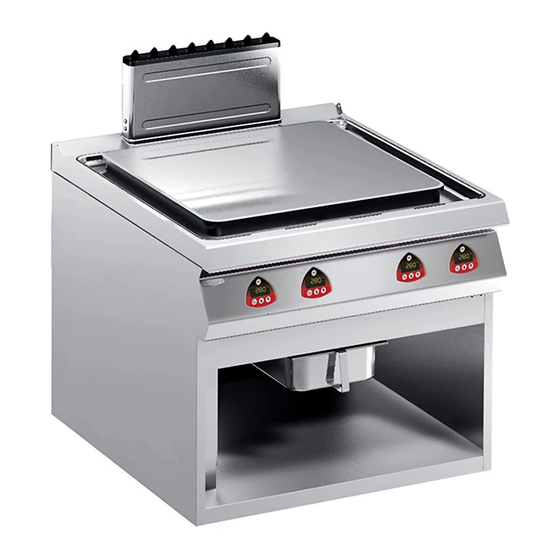
PIASTRA DI COTTURA ELETTRICA
ELECTRIC COOKING PLATE
191TPE
ELEKTRO-BRATPLATTE
PLAQUE DE CUISSON ÉLECTRIQUE
PLANCHA DE COCCIÓN ELÉCTRICA
MANUALE D'USO E INSTALLAZIONE
USE AND INSTALLATION MANUAL
BEDIEN- UND INSTALLATIONSHANDBUCH
MANUEL D'UTILISATION ET D'INSTALLATION
MANUAL DE USO E INSTALACIÓN
IT
Italiano
GB
English
DE
Deutsch
FR
Français
ES
Español
Ed. 1
05/2011
3166950
Advertisement
Chapters
Table of Contents

Related Manuals for Angelo Po 191TPE


Summary of Contents for Angelo Po 191TPE
- Page 1 PIASTRA DI COTTURA ELETTRICA ELECTRIC COOKING PLATE 191TPE ELEKTRO-BRATPLATTE PLAQUE DE CUISSON ÉLECTRIQUE PLANCHA DE COCCIÓN ELÉCTRICA MANUALE D’USO E INSTALLAZIONE USE AND INSTALLATION MANUAL BEDIEN- UND INSTALLATIONSHANDBUCH MANUEL D’UTILISATION ET D’INSTALLATION MANUAL DE USO E INSTALACIÓN Italiano English Deutsch Français...
-
Page 3: Table Of Contents
INDICE rif. capitoli pag. 1 INFORMAZIONI GENERALI ..........2 2 INFORMAZIONI TECNICHE ..........4 3 SICUREZZA ............... 6 PARTE 4 USO E FUNZIONAMENTO ..........7 5 MANUTENZIONI .............. 11 6 GUASTI ................13 7 MOVIMENTAZIONE E INSTALLAZIONE ......15 8 REGOLAZIONI ..............19 9 SOSTITUZIONE PARTI ........... -
Page 4: Informazioni Generali
INFORMAZIONI GENERALI RACCOMANDAZIONI PER IL LETTORE Per rintracciare facilmente gli argomenti specifici di parte: contiene tutte le informazioni ne- interesse, consultare l’indice analitico posto all’ini- cessarie ai destinatari omogenei, cioè tutti gli zio del manuale. operatori esperti e autorizzati a movimentare, Questo manuale è... - Page 5 IDENTIFICAZIONE COSTRUTTORE E APPARECCHIATURA La targhetta di identificazione raffigurata è applicata G)Grado di protezione direttamente sull'apparecchiatura. In essa sono ri- H)Paese di destinazione portati i riferimenti e tutte le indicazioni indispensa- L) Tensione (V) bili alla sicurezza di esercizio. M)Assorbimento (A) N)Frequenza (Hz) A) Modello apparecchiatura P)Potenza dichiarata (kW)
-
Page 6: Informazioni Tecniche
INFORMAZIONI TECNICHE DESCRIZIONE GENERALE APPARECCHIATURA La piastra di cottura, d'ora innanzi definita apparec- chiatura, è stata progettata e costruita per la cottura dei cibi a diretto contatto con la piastra, nell'ambito della ristorazione professionale. Organi principali A)Piastra di cottura: è realizzata in acciaio inox. B)Scarico fumi (tipo A): per evacuare il calore ge- nerato dalle resistenze. - Page 7 SEGNALI DI SICUREZZA E INFORMAZIONE L'illustrazione indica la posizione dei segnali applicati. A)Targa identificazione costruttore e apparec- chiatura. B)Pericolo di scottatura: fare attenzione alle su- perfici calde. C)Pericolo generico: durante il lavaggio dell'appa- recchiatura non dirigere getti d'acqua in pressio- ne sulle parti interne.
-
Page 8: Sicurezza
SICUREZZA NORME PER LA SICUREZZA Il costruttore, in fase di progettazione e costruzione, acquisita nel settore specifico di intervento. ha posto particolare attenzione agli aspetti che pos- Per mantenere l'igiene e proteggere gli alimenti la- sono provocare rischi alla sicurezza e alla salute vorati da tutti i fenomeni di contaminazione, è... -
Page 9: Uso E Funzionamento
– Problematiche locali relative all'impatto ambien- In riferimento alla direttiva RAEE 2002/96 (Rifiuti di tale Apparecchiature Elettriche ed Elettroniche), l'utiliz- A tale scopo, il costruttore fornisce alcune indica- zatore, in fase di dismissione, deve smaltire le ap- zioni che dovranno essere considerate da tutti colo- parecchiature negli appositi centri di raccolta sono autorizzati... - Page 10 DESCRIZIONE COMANDI Sull'apparecchiatura sono disposti i comandi per at- D)Pulsante impostazione potenza: per impostare tivare le funzioni principali. la potenza di riscaldamento. A)Pulsante avviamento e arresto cottura E)Display digitale: visualizza i parametri di lavoro (ON/OFF): serve per avviare o arrestare il ciclo di e le sigle di allarme.
- Page 11 ACCENSIONE E SPEGNIMENTO APPARECCHIATURA Accensione 1 - Agire sull'interruttore automatico sezionatore per attivare l'allacciamento alla linea elettrica principale. La spia di rete (M) si accende. 2 - Premere il pulsante (A) per portare in "stand- by" l'apparecchiatura. La spia di rete (M) si spegne. La spia resistenze (L) si accende ed il display (E) visualizza la videata raffigurata.
- Page 12 – Premere il pulsante (3 volte) per attivare contem- poraneamente tutte le resistenze (vedi schemi elettrici allegati). Le spie resistenze (L1-L2-L3) si accendono. 3 - Premere i tasti (B-C) per aumentare o diminuire la temperatura di cottura. Importante Il preriscaldamento viene escluso automa- ticamente se la temperatura impostata è...
-
Page 13: Manutenzioni
INATTIVITÀ PROLUNGATA DELL’APPARECCHIATURA Se l'apparecchiatura rimane inattiva per un lungo 3 - Cospargere con un velo d'olio alimentare le su- tempo, procedere nel modo indicato. perfici in acciaio inox. 1 - Agire sull'interruttore sezionatore dell'apparec- 4 - Eseguire tutte le operazioni di manutenzione. chiatura per disattivare l'allacciamento alla li- 5 - Ricoprire l'apparecchiatura con un involucro e nea elettrica principale. - Page 14 PULIZIA APPARECCHIATURA Se si considera che l'apparecchiatura è utilizzata 3 - Pulire gli accessori dopo l'uso, con uno sgras- per la preparazione di prodotti alimentari per l'uo- sante idoneo. Si consiglia il lavaggio in lavasto- mo, è necessario prestare particolare cura a tutto viglie.
-
Page 15: Guasti
IDM-39617101000_2.tif GUASTI RICERCA GUASTI L'apparecchiatura, prima della messa in servizio, è dall'utilizzatore, per tutti gli altri è richiesta una stata preventivamente collaudata. Le informazioni precisa competenza tecnica o particolari ca- di seguito riportate hanno lo scopo di aiutare l'iden- pacità e quindi devono essere eseguiti esclu- tificazione e correzione di eventuali anomalie e di- sivamente da personale qualificato con sfunzioni che potrebbero presentarsi in fase d'uso. - Page 16 TABELLA SEGNALAZIONE ALLARMI Se il problema o l'inconveniente riscontrato non rientra nelle anomalie riportate in tabella è necessa- rio consultare la tabella "Segnalazione allarmi" di seguito riportata. Le informazioni di seguito riportate hanno lo scopo di identificare i segnali di allarme che compaiono sui display (E).
-
Page 17: Movimentazione E Installazione
MOVIMENTAZIONE E INSTALLAZIONE RACCOMANDAZIONI PER LA MOVIMENTAZIONE E INSTALLAZIONE Importante Eseguire la movimentazione e l'installazio- ste operazioni dovrà, se necessario, orga- ne nel rispetto delle informazioni fornite dal nizzare “piano sicurezza” costruttore e riportate direttamente sull'im- salvaguardare l'incolumità delle persone ballo, sull'apparecchiatura e nelle istruzioni direttamente coinvolte. - Page 18 MOVIMENTAZIONE E SOLLEVAMENTO L'apparecchiatura può essere movimentata con un dispositivo di sollevamento a forche o a gancio di portata adeguata. Prima di effettuare questa opera- zione, controllare la posizione del baricentro del ca- rico. IDM-39611801100.tif INSTALLAZIONE APPARECCHIATURA Tutte le fasi di installazione devono essere conside- rate sin dalla realizzazione del progetto generale.
- Page 19 MONTAGGIO APPARECCHIATURE IN BATTERIA Per montare le apparecchiature in batteria (fianco a fianco) procedere nel modo indicato. 1 - Svitare le viti (C) e smontare i cruscotti (B). 2 - Applicare, sui bordi da accostare, del nastro adesivo di protezione. 3 - Applicare, sui lati da accostare, del sigillante per uso alimentare.
- Page 20 ALLACCIAMENTO ELETTRICO Effettuare l'allacciamento dell'apparecchiatura alla Importante rete di alimentazione nel modo indicato. 1 - Installare, se non è presente, un interruttore se- L'allacciamento deve essere effettuato da zionatore (A) vicino all'apparecchiatura con personale autorizzato e qualificato, nel ri- sganciatore magnetotermico e blocco differen- spetto delle leggi vigenti in materia e con l'utilizzo di materiale appropriato e prescrit- ziale.
-
Page 21: Regolazioni
COLLAUDO APPARECCHIATURA 1 - Verificare che la tensione di rete sia conforme a Importante quella dell'apparecchiatura. 2 - Agire sull'interruttore sezionatore automatico Prima della messa in servizio, deve essere per verificare il collegamento elettrico. eseguito il collaudo dell'impianto, al fine di 3 - Verificare il corretto funzionamento dei disposi- valutare le condizioni operative di ogni sin- golo componente ed individuare le even-... - Page 23 CONTENTS ref. chapters page 1 GENERAL INFORMATION ..........2 2 TECHNICAL INFORMATION ..........4 3 SAFETY ................6 PART 4 USE AND OPERATION ............. 7 5 SERVICING ..............11 6 FAULT ................13 7 HANDLING AND INSTALLATION ........15 8 ADJUSTMENTS ............... 19 9 REPLACING PARTS ............
-
Page 24: General Information
GENERAL INFORMATION INFORMATION FOR THE READER To find the specific topics of interest to you quickly, 2nd part: contains all the information neces- refer to the index at the start of the manual. sary for special categories of reader, i.e. all This manual is subdivided into two parts. - Page 25 IDENTIFICATION OF CONSTRUCTOR AND APPLIANCE The nameplate shown here is fitted directly to the G)Protection rating appliance. It contains references and all essential H)Country of destination information for operating safety. L) Voltage (V) A)Appliance model M)Absorption (A) B)Type of customisation N)Frequency (Hz) C)Constructor identification P)Rated power (kW)
-
Page 26: Technical Information
TECHNICAL INFORMATION GENERAL DESCRIPTION OF APPLIANCE The cooking plate, referred to from now on as the appliance, is designed and produced for cooking fo- ods in direct contact with the plate in the professio- nal catering sector. Main Parts A)Cooking plate: in stainless steel B)Fume exhaust vent (type A): evacuates the heat generated by the heating elements C)Control panel: controls the appliance's opera-... - Page 27 SAFETY AND INFORMATION SIGNS The illustration shows the position of the signs pro- vided. A)Nameplate with manufacturer and appliance data. B)Burn hazard: watch out for hot surfaces. C)General hazard: when washing the appliance do not point pressurised water jets at internal parts. D)General hazard: read the manual carefully be- fore carrying out any procedure.
-
Page 28: Safety
SAFETY SAFETY REGULATIONS During design and construction, the constructor has To maintain hygiene and protect the food proc- paid special attention to factors which may cause essed from all forms of contamination, all elements risks to the health and safety of the people interact- in direct or indirect contact with foodstuffs and all ing with the appliance. -
Page 29: Use And Operation
For this purpose, the manufacture supplies informa- Under the WEEE (Waste Electrical and Electronic tion which must be considered by all those author- Equipment) Directive 2002/96/EC, when scrapping ised to interact with the appliance during its equipment the user must dispose of it at the specific expected lifetime, in order to prevent environmental authorised disposal centres, or reconsign it, still in- impact. - Page 30 DESCRIPTION OF CONTROLS The appliance is fitted with the controls for use of its D)Power setting key: for setting the heating main functions. power. A)Cooking start and stop key E)Digital display: displays the working parameters (ON/OFF): for starting or stopping the cooking and alarm codes.
- Page 31 SWITCHING THE APPLIANCE ON AND OFF Lighting 1 - Turn on the appliance's circuit breaker to con- nect it to the electrical mains. The mains light (M) comes on. 2 - Press the (A) key to set the appliance in "stand- by"...
- Page 32 – Press the key (3 times) to switch on all the hea- ting elements together (see attached wiring dia- grams). The heating element lights (L1-L2-L3) come on. 3 - Press the keys (B-C) to increase or decrease the cooking temperature. Important Preheating is automatically disabled if the temperature set is above the default tempe-...
-
Page 33: Servicing
LENGTHY DOWNTIMES OF APPLIANCE If the appliance is to be out of use for a lengthy pe- 3 - Spread a film of edible oil over the stainless riod, proceed as follows. steel surfaces. 1 - Cut off the mains electricity supply using the ap- 4 - Carry out all the servicing procedures. - Page 34 CLEANING INSTRUCTIONS Since the appliance is used for preparing foods for 3 - After use, clean the accessories with a suitable human consumption, special care must be paid to grease-remover product. If possible, wash in everything relating to hygiene, and the appliance the dishwasher.
-
Page 35: Fault
IDM-39617101000_2.tif FAULT TROUBLESHOOTING The appliance has been tested before being put problems himself, but for others specific tech- into service. The information provided below is in- nical knowledge or skill is required, and so tended to assist in the identification and correction they must only be carried out by qualified staff of any anomalies and malfunctions which might oc- with recognised experience acquired in the... - Page 36 TABLE OF ALARM INDICATIONS If the problem or fault noticed is not amongst those listed in the table, consult the "Key to Alarms" table provided below. The information provided below s intended to iden- tify the alarm signals which appear on the display (E).
-
Page 37: Handling And Installation
HANDLING AND INSTALLATION RECOMMENDATIONS FOR HANDLING AND INSTALLATION Important When handling and installing the appliance use. If necessary, the person authorised to comply with the information provided by carry out these operations must organise a the constructor directly on the packaging, "safety plan"... - Page 38 HANDLING AND LIFTING The appliance can be handled using fork-lift or hook equipment of suitable load-carrying capacity. Be- fore lifting, check the position of the load's centre of gravity. IDM-39611801100.tif INSTALLATION OF THE APPLIANCE All installation stages must be considered right from production of the general layout.
- Page 39 ASSEMBLY APPLIANCES IN BANKS To assemble appliances in banks (side by side) proceed as described below. 1 - Undo the screws (C) and remove the control panels (B). 2 - Apply masking tape to the edges to be placed side by side. 3 - Apply food-approved sealant to the edges to be placed side by side.
- Page 40 ELECTRICAL CONNECTION Connect the appliance to the mains electricity sup- Important ply as follows. 1 - If not already present, install a circuit-breaker The connection must be made by author- (A) with overload cutout and differential safety ised, skilled personnel, in accordance with breaker close to the appliance.
-
Page 41: Adjustments
TESTING OF THE APPLIANCE 1 - Check that the mains voltage is the same as Important that of the appliance. 2 - Operate the appliance's circuit-breaker to Before it is put into service, the system check the electrical connection. must be tested to check the operating con- 3 - Check that the safety device is operating cor- ditions of every single component and identify any malfunctions. - Page 43 INHALTSVERZEICHNIS Ref. Kapitel Seite 1 ALLGEMEINES ..............2 2 TECHNISCHE INFORMATIONEN ........4 3 SICHERHEIT ..............6 1. TEIL 4 GEBRAUCH UND BETRIEB ..........7 5 WARTUNG ............... 11 6 DEFEKTE ................. 13 7 HANDHABUNG UND INSTALLATION ......15 8 EINSTELLUNGEN ............19 9 AUSTAUSCH VON BAUTEILE ........
-
Page 44: Allgemeines
ALLGEMEINES INFORMATIONEN FÜR DEN LESER Konsultieren Sie das Sachregister, das am Anfang 2. Teil: Diese Informationen wenden sich an des Handbuchs zu finden ist, um leichter unter be- eine bestimmte Zielgruppe. Sie sind für erfahre- stimmten Themen von besonderem Interesse ne Bediener bestimmt, die für Handhabung, nachschlagen zu können. - Page 45 TYPENSCHILD FÜR HERSTELLER UND GERÄT Das abgebildete Typenschild wird direkt auf dem G)Schutzart Gerät aufgebracht. Es enthält sämtliche Angaben H)Bestimmungsland und Hinweise, die für den sicheren Betrieb unerläs- L) Spannung (V) slich sind. M)Stromaufnahme (A) A)Gerätemodell N)Frequenz (Hz) B)Art der Anpassung P)Angabe der Leistung (Kw) C)Angabe des Herstellers Q)Abnahmespannungsanzeige...
-
Page 46: Technische Informationen
TECHNISCHE INFORMATIONEN ALLGEMEINE BESCHREIBUNG DES GERÄTS Die Bratplatte, die im Folgenden als Gerät bezeich- net wird, wurde für den Gebrauch in Restaurantbe- trieben zum Braten von Speisen direkt auf der Platte projektiert und konstruiert. Hauptorgane A)Kochplatte: aus Edelstahl B)Rauchabzug (Typ A): Zum Abführen der von den Heizwiderständen erzeugten Wärme C)Kontrolltafel: um die Betriebsfunktionen des Gerätes zu verwalten. - Page 47 SICHERHEITSHINWEISE UND INFORMATIONEN Die Abbildung zeigt die Anordnung der aufgekleb- ten Sicherheitshinweise. A)Typenschild mit Angabe des Herstellers und der Gerätekenndaten. B)Verbrennungsgefahr: Vorsicht vor heißen Flä- chen. C)Allgemeine Gefahr: Beim Waschen des Geräts den Wasserstrahl nicht direkt auf die inneren Tei- le richten.
-
Page 48: Sicherheit
SICHERHEIT SICHERHEITSVORSCHRIFTEN Der Hersteller hat bei Entwicklung und Fertigung die- Aus hygienischen Gründen und zum Schutz vor ses Produkts besondere Sorgfalt auf Aspekte verwen- jeglicher Form der Kontamination der Nahrungsmit- det, die eine Gefahr für die Sicherheit und die tel müssen die Elemente, die direkt oder indirekt mit Gesundheit der Personen, die dieses Gerät handha- den Nahrungsmitteln in Berührung kommen sowie ben, hervorrufen können. -
Page 49: Gebrauch Und Betrieb
– Ortsgebundene Probleme in Hinblick auf die Um- Gemäß der WEEE-Richtlinie 2002/96/EG (Elektro- weltbelastung und Elektronik-Altgeräte) muss der Betreiber bei Zu diesem Zweck gibt der Hersteller einige Hinwei- der endgültigen Außerbetriebnahme die Geräte bei se, die von jedem, der zur Interaktion mit dem Gerät den hierfür vorgesehenen Rücknahmestellen abge- während seines vorgesehenen Lebenszyklus be- ben oder im Moment des Erwerbs neuer Geräte un-... - Page 50 BESCHREIBUNG DER BEDIENELEMENTE Das Gerät ist mit Bedienelementen zur Aktivierung D)Taste für Leistungswahl: zur Wahl der Heizlei- der wichtigsten Funktionen ausgestattet. stung. A)Taste zum Starten und Stoppen der Garung E)Digitales Display: zur Anzeige der Betriebspa- (ON/OFF): Sie dient zum Start oder Stopp des rameter und Abkürzungen der Fehlermeldungen.
- Page 51 EIN- UND AUSSCHALTEN DES GERÄTS Zündung 1 - Mit dem Trennschalter den Anschluss an das Stromnetz herstellen. Die Kontrollleuchte Gaszufuhr (M) schaltet sich ein. 2 - Taste (A) drücken, um das Gerät auf Bereit- schaft („Stand-by") zu schalten. Die Kontrollleuchte (M) erlischt. Die Widerstände-Kontrollleuchte (L) leuchtet auf, und auf dem Display (E) erscheint das dar- gestellte Bild.
- Page 52 – Taste (dreimalig) drücken, um gleichzeitig alle Widerstände einzuschalten (siehe Schaltpläne in Anlage). Die Widerstände-Kontrollleuchten (L1- L2-L3) leuchten auf. 3 - Die Tasten (B-C) drücken, um die Gartempera- tur zu erhöhen oder zu verringern. Wichtig Das Vorheizen wird automatisch deakti- viert, sollte die eingestellte Temperatur über dem vorbesetzten Wert liegen.
-
Page 53: Wartung
LÄNGERER STILLSTAND DES GERÄTS Verfahren Sie folgendermaßen, falls das Gerät län- 3 - Tragen Sie eine hauchdünne Schicht Lebens- gere Zeit nicht eingesetzt werden soll: mittelöl auf die Edelstahlflächen auf. 1 - Das Gerät mit seinem Trennschalter vom 4 - Führen Sie sämtliche Wartungsarbeiten aus. Hauptstromnetz trennen. - Page 54 REINIGUNG DES GERÄTS Da das Gerät zur Zubereitung von Speisen für den 3 - Die Zubehörteile nach dem Gebrauch mit ei- Menschen eingesetzt wird, ist besondere Sorgfalt nem geeigneten Fettlöser reinigen. Wir emp- auf die Hygiene geboten. Das Gerät und dessen fehlen die Reinigung im Geschirrspüler.
-
Page 55: Defekte
IDM-39617101000_2.tif DEFEKTE FEHLERSUCHE Vor der Inbetriebnahme wurde das Gerät einem alle anderen erfordern präzise Fachkenntnis- vorläufigen Testlauf unterzogen. Die im Folgenden se oder besondere Fähigkeiten und dürfen da- aufgeführten Informationen sollen Ihnen dabei hel- her ausschließlich von qualifiziertem Personal fen, eventuelle Anomalien oder Funktionsstörun- mit nachweislicher Erfahrung in diesem spezi- gen, die während des Betriebs auftreten können, ellen Gebiet des Eingriffs durchgeführt wer-... - Page 56 TABELLE DER FEHLERMELDUNGEN Wenn das aufgetretene Problem nicht unter die in der Tabelle angegebenen Störungen fällt, die nach- stehende Tabelle "Fehlermeldungen" konsultieren. Die nachstehenden Informationen dienen zur Iden- tifikation der Fehlermeldungen, die auf der Anzeige (E) angezeigt werden. IDM-39617100600.tif Fehlermeldung Störung Lösung Anmerkungen...
-
Page 57: Handhabung Und Installation
HANDHABUNG UND INSTALLATION EMPFEHLUNGEN FÜR DIE INSTALLATION UND HANDHABUNG Wichtig Beachten Sie die Hinweise des Herstellers, nen autorisierte Person wird bei Bedarf die direkt auf der Verpackung, auf dem Ge- einen „Sicherheitsplan" aufstellen müssen, rät selbst oder in der Gebrauchsanweisung um die Unversehrtheit der direkt an dem zu finden sind, wenn Sie das Gerät handha- Vorgang beteiligten Personen zu gewähr-... - Page 58 HANDHABUNG UND HUB Das Gerät kann mit einem Hubmittel bewegt wer- den, das mit Gabeln oder Haken ausgestattet ist und die geeignete Traglast besitzt. Vor diesem Vor- gang ist der Schwerpunkt der Last zu überprüfen. IDM-39611801100.tif INSTALLATION DES GERÄTS Es müssen sämtliche Phasen der Installation, schon von der Umsetzung des allgemeinen Projekts an, be- rücksichtigt werden.
- Page 59 MONTAGE BEI REIHENAUFSTELLUNG Verfahren Sie folgendermaßen, um Geräte (neben- einander) in einer Reihe aufzustellen. 1 - Die Schrauben (C) ausschrauben und die Blen- den (B) ausbauen. 2 - Bekleben Sie die Gerätekanten, die nebenein- ander angeordnet werden sollen, mit einem Schutzband.
- Page 60 STROMANSCHLUSS Den Anschluss des Geräts an das Stromnetz in der Wichtig angegebenen Weise ausführen. 1 - Falls nicht schon vorhanden, einen Trennschal- Der Anschluss muss von autorisiertem ter (A) mit thermomagnetischem Auslöser und Fachpersonal in Einklang mit den einschlä- FI-Block in der Nähe des Geräts installieren. gigen gesetzlichen Bestimmungen und un- 2 - Durch Lösen der Schrauben (B) die Schutzab- Verwendung...
-
Page 61: Einstellungen
TESTLAUF ZUR ABNAHME DES GERÄTS 1 - Sicherstellen, dass die Netzspannung der Wichtig Nennspannung des Geräts entspricht. 2 - Den Trennschalter betätigen , um den Strom- Vor der Inbetriebnahme muss ein Testlauf anschluss zu überprüfen. der Anlage durchgeführt werden, um den 3 - Eine Funktionsprüfung der Sicherheitseinrich- Betriebszustand jeder einzelnen Kompo- nente zu überprüfen und eventuelle An-... - Page 63 INDEX réf. chapitres page 1 INFORMATIONS GÉNÉRALES ......... 2 2 INFORMATIONS TECHNIQUES ........4 3 SÉCURITÉ ................. 6 PARTIE 4 UTILISATION ET FONCTIONNEMENT ......7 5 ENTRETIEN ..............11 6 PANNES ................13 7 MANUTENTION ET INSTALLATION ....... 15 8 RÉGLAGES ..............19 9 REMPLACEMENT DE PIÈCES ........
- Page 64 INFORMATIONS GÉNÉRALES INFORMATIONS POUR LE LECTEUR Pour retrouver facilement les sujets qui vous inté- 2e partie: elle contient toutes les informa- ressent, consulter l’index analytique au début du tions nécessaires aux destinataires homogè- manuel. nes, c'est-à-dire tous les opérateurs experts Ce manuel est divisé...
- Page 65 IDENTIFICATION DU FABRICANT ET DE L’APPAREIL La plaque d’identification représentée, est appli- G)Degré de protection quée directement sur l'appareil. Elle reporte les ré- H)Pays de destination férences et les indications indispensables à la L) Tension (V) sécurité. M)Absorption (A) A)Modèle de l’appareil N)Fréquence (Hz) B)Type de personnalisation P)Puissance déclarée (kW)
- Page 66 INFORMATIONS TECHNIQUES DESCRIPTION GÉNÉRALE DE L'APPAREIL La plaque de cuisson, que l'on appellera mainte- nant appareil, a été conçue et fabriquée pour la cuisson d'aliments en contact direct avec la plaque, dans le domaine de la restauration professionnelle. Organes principaux A)Plaque de cuisson: en acier inox B)Évacuation des fumées (type A) : pour évacuer la chaleur générée par les résistances...
- Page 67 SIGNAUX DE SÉCURITÉ ET INFORMATION L’illustration indique la position des signaux appliqués. A)Plaque d'identification du fabricant et de l'ap- pareil. B)Risque de brûlure: attention aux surfaces chau- des. C)Risque générique: pendant le lavage de l'appa- reil ne pas diriger de jets d'eau sous pression sur les pièces intérieures.
- Page 68 SÉCURITÉ NORMES DE SÉCURITÉ Le fabricant, lors de la conception et de la fabrica- Pour maintenir l'hygiène et protéger les aliments de tion, a fait très attention aux aspects qui peuvent tous les phénomènes de contamination, il faut net- provoquer des risques à la sécurité et à la santé des toyer soigneusement les éléments qui sont en con- personnes qui interagissent avec l’appareil.
- Page 69 – Problèmes locaux relatifs à l'impact environne- En référence à la Directive DEEE 2002/96/CE (dé- mental chets d’équipements électriques et électroniques), Pour cela le fabricant fournit quelques indications l'utilisateur, lorsqu’il veut éliminer les appareils, doit qui devront être considérées par tous ceux autori- les transporter vers des points de collecte agréés, sés à...
- Page 70 DESCRIPTION DES COMMANDES Sur l’appareil sont disposées les commandes pour D)Touche de sélection de la puissance : pour sé- activer les fonctions principales. lectionner la puissance de chauffe. A)Touche de mise en marche et d’arrêt de la E)Afficheur numérique : il affiche les paramètres cuisson (ON/OFF) : elle sert pour faire partir ou de travail et les sigles d’alarme.
- Page 71 ALLUMAGE ET EXTINCTION DE L’APPAREIL Allumage 1 - Agir sur l'interrupteur sectionneur automatique pour activer le branchement à la ligne électri- que principale. Le voyant de réseau (M) s’allume. 2 - Presser la touche (A) pour porter l’appareil en « stand-by ». Le voyant de réseau (M) s’éteint.
- Page 72 – Presser la touche (3 fois) pour activer simultané- ment toutes les résistances (voir schémas élec- triques annexés). Les voyants des résistances (L1-L2-L3) s’allument. 3 - Presser les touches (B-C) pour augmenter ou diminuer la température de cuisson. Important Le préchauffage est exclu automatique- ment si la température sélectionnée est su- périeure à...
- Page 73 INUTILISATION PROLONGÉE DE L’APPAREIL Si l'appareil reste inactif pendant longtemps, procé- 3 - Étaler un voile d’huile alimentaire sur les surfa- der comme suit. ces en acier inox. 1 - Agir sur l'interrupteur sectionneur de l’appareil 4 - Exécuter toutes les opérations d’entretien. pour désactiver le branchement à...
- Page 74 NETTOYAGE DE L’APPAREIL Étant donné que l'appareil est utilisé pour la prépa- 3 - Nettoyer les accessoires après leur utilisation ration de produits alimentaires pour l'homme, il faut avec un dégraissant approprié. Le lavage en faire attention à tout ce qui concerne l'hygiène; l'ap- lave-vaisselle est conseillé.
- Page 75 IDM-39617101000_2.tif PANNES DÉPANNAGE Avant sa mise en service, l’appareil a été essayé. pour tous les autres il faut une compétence Les informations reportées ci-après ont pour but technique précise ou des capacités particuliè- d’aider à l'identification et à la correction d’éven- res;...
- Page 76 TABLEAU SIGNALISATIONS DES ALARMES Si le problème ou l'inconvénient relevé ne fait pas partie des pannes reportées dans le tableau, con- sulter le tableau "Signalisation des alarmes" reporté ci-dessous. Les informations ci-dessous ont pour but d'identifier les signaux d'alarme qui apparaissent sur les affi- cheurs (E).
- Page 77 MANUTENTION ET INSTALLATION RECOMMANDATIONS POUR LA MANUTENTION ET L’INSTALLATION Important Effectuer la manutention et l’installation en effectuer ces opérations devra, si nécessai- respectant les informations fournies par le re, organiser un « plan de sécurité » pour fabricant, reportées directement sur l’em- sauvegarder la sécurité...
- Page 78 MANUTENTION ET LEVAGE L'appareil peut être manutentionné avec un dispo- sitif de levage à fourches ou à crochet d’une capa- cité de charge appropriée. Avant d’effectuer cette opération, contrôler la position du centre de gravité de la charge. IDM-39611801100.tif MISE EN PLACE DE L’APPAREIL Toutes les phases de mise en place doivent être prises en considération, dès la réalisation du projet général.
- Page 79 MONTAGE DES APPAREILS EN BATTERIE Pour monter les appareils en batterie (les uns à côté des autres), procéder comme suit. 1 - Dévisser les vis (C) et démonter les tableaux de commandes (B). 2 - Appliquer, sur les bords à rapprocher, du ruban adhésif de protection.
- Page 80 BRANCHEMENT ÉLECTRIQUE Effectuer le branchement de l'appareil au réseau Important électrique d'alimentation comme suit. 1 - Installer, s’il n’est pas présent, un interrupteur Le branchement doit être fait par du per- sectionneur (A) près de l’appareil avec déclen- sonnel autorisé et qualifié, conformément cheur magnétothermique et bloc différentiel.
- Page 81 ESSAI DE L’APPAREIL 1 - Vérifier que la tension de réseau corresponde à Important celle de l’appareil. 2 - Agir sur l’interrupteur sectionneur automatique Avant la mise en service, l’essai de l’instal- pour vérifier le branchement électrique. lation doit être fait pour évaluer les condi- 3 - Vérifier le fonctionnement correct des disposi- tions opérationnelles...
- Page 83 ÍNDICE ref. capítulos pág 1 INFORMACIONES DE CARÁCTER GENERAL ....2 2 INFORMACIONES DE CARÁCTER TÉCNICO ....4 3 SEGURIDAD ..............6 PARTE 4 USO Y FUNCIONAMIENTO ..........7 5 MANTENIMIENTO ............11 6 AVERÍAS ................13 7 DESPLAZAMIENTO E INSTALACIÓN ......15 8 REGULACIONES .............
-
Page 84: Informaciones De Carácter General
INFORMACIONES DE CARÁCTER GENERAL INFORMACIONES PREVIAS Para ubicar fácilmente los temas específicos de in- 2a parte: contiene todas las informaciones terés, consúltese el índice analítico que se encuen- necesarias para destinatarios homogéneos, tra al inicio del manual. esto es, todos los operadores expertos y au- Este manual comprende dos partes. - Page 85 IDENTIFICACIÓN FABRICANTE Y EQUIPO La placa de identificación fijada directamente en el G)Grado de protección equipo reproduce todas las referencias e indicacio- H)País de destino nes indispensables para la seguridad de servicio. L) Tensión (V) A)Modelo del aparato M)Consumo (A) B)Tipo de personalización N)Frecuencia (Hz) C)Identificación fabricante...
-
Page 86: Informaciones De Carácter Técnico
INFORMACIONES DE CARÁCTER TÉCNICO DESCRIPCIÓN GENERAL DEL EQUIPO La plancha de cocción, que de ahora en adelante llamaremos aparato, ha sido proyectada y fabrica- da para cocer alimentos mediante contacto directo con la plancha misma, en el sector de la restaura- ción profesional. - Page 87 SEÑALIZACIONES DE SEGURIDAD E INFORMACIÓN La ilustración indica la posición de las señalizacio- nes fijadas en el equipo. A)Placa de identificación fabricante y aparato. B)Peligro de quemaduras: prestar atención a las superficies calientes. C)Peligro genérico: durante el lavado del aparato no dirigir chorros de agua a presión hacia sus partes internas.
-
Page 88: Seguridad
SEGURIDAD NORMAS DE SEGURIDAD Durante las fases de diseño y producción el fabri- riencia reconocida y adquirida en el sector cante ha prestado especial atención a los factores específico de la intervención. que pueden provocar riesgos en cuanto a seguri- Para mantener la higiene y proteger los alimentos dad y salud de las personas que interactúan con el trabajados respecto de cualquier fenómeno de con-... -
Page 89: Uso Y Funcionamiento
Es por ello que, con el fin de prevenir el impacto Conforme con la Directiva RAEE 2002/96/CE (so- ambiental, el fabricante entrega algunas instruccio- bre residuos de aparatos eléctricos y electrónicos), nes que deberán ser respetadas por todas las per- al efectuar la eliminación de los equipos el usuario sonas autorizadas para interactuar con el aparato deberá... - Page 90 DESCRIPCIÓN DE LOS MANDOS Para activar las funciones principales, en el equipo D)Tecla de programación de la potencia: para pro- se han instalado los siguientes mandos. gramar la potencia de calentamiento. A)Tecla de puesta en marcha y detención de la E)Display digital: muestra los parámetros de trabajo y cocción (ON/OFF): sirve para activar o interrum- las siglas de alarma.
- Page 91 ENCENDIDO Y APAGADO DEL APARATO Encendido 1 - Operar con el interruptor automático aislador para activar la conexión a la línea eléctrica prin- cipal. Se enciende el testigo de red (M). 2 - Presionar la tecla (A) para disponer en "stand- by"...
- Page 92 – Presionar la tecla (3 veces) para activar simultá- neamente todas las resistencias (véanse los es- quemas eléctricos adjuntos). Se encienden los testigos resistencias (L1-L2-L3). 3 - Presionar las teclas (B-C) para aumentar o re- ducir la temperatura de cocción. Importante El precalentamiento es automáticamente inhabilitado si la temperatura programada...
-
Page 93: Mantenimiento
PERÍODO PROLONGADO DE INACTIVIDAD DEL EQUIPO En caso de que el equipo deba permanecer inacti- 3 - Esparcir sobre las superficies de acero inoxida- vo durante un período prolongado de tiempo, se ble una capa delgada de aceite comestible. deberán efectuar las siguientes operaciones. 4 - Efectuar todas las operaciones de manteni- 1 - Con el interruptor aislador del aparato desacti- miento. - Page 94 LIMPIEZA APARATO Atendida la circunstancia de que el equipo es utili- 3 - Limpiar los accesorios después del uso utili- zado para la preparación de productos alimenticios zando un desengrasante adecuado. Se acon- para el consumo humano, es necesario prestar es- seja efectuar el lavado en lavavajillas.
-
Page 95: Averías
IDM-39617101000_2.tif AVERÍAS BÚSQUEDA DE AVERÍAS Antes de la puesta en servicio, el equipo ha sido so- Algunos de estos problemas pueden ser re- sueltos por el usuario, pero otros requieren metido a prueba de funcionamiento. una competencia técnica precisa o determina- Las siguientes informaciones tienen por objeto faci- das capacidades, razón por la cual deben ser litar la identificación y corrección de eventuales... - Page 96 BÚSQUEDA DE AVERÍAS En caso de que el problema o el inconveniente no esté mencionado entre las anomalías de la tabla anterior, consultar la tabla de "Señalización de las alarmas" que se detalla a continuación. Dichas informaciones sirven para que el usuario lo- gre identificar las señales de alarma que se visuali- zan en el indicador (E).
-
Page 97: Desplazamiento E Instalación
DESPLAZAMIENTO E INSTALACIÓN RECOMENDACIONES PARA EL DESPLAZAMIENTO Y LA INSTALACIÓN Importante Efectuar el desplazamiento e instalación rizada para efectuar estas operaciones de- respetando las indicaciones proporciona- berá, si fuera necesario, organizar un "plan das por el fabricante, reproducidas directa- de seguridad", a fin de salvaguardar la in- mente sobre el embalaje, en el equipo y en columidad de las personas directamente las instrucciones de uso. - Page 98 DESPLAZAMIENTO Y ELEVACIÓN El equipo puede ser desplazado con un equipo de elevación de horquillas o de gancho, de capacidad adecuada. Para ejecutar esta operación se debe controlar atentamente el centro de gravedad de la carga. IDM-39611801100.tif INSTALACIÓN DEL EQUIPO Durante la realización del proyecto general, deben ser consideradas todas las fases de la instalación.
- Page 99 MONTAJE DE EQUIPOS EN BATERÍA Para montar los equipos en batería (uno al lado del otro) aplicar las siguientes instrucciones. 1 - Desenroscar los tornillos (C) y desmontar los paneles de mando (B). 2 - Poner cinta adhesiva de protección sobre los bordes a juntar.
- Page 100 CONEXIÓN ELÉCTRICA Conectar el aparato a la red eléctrica de alimenta- Importante ción respetando las siguientes instrucciones. 1 - En caso de no estar presente, instalar un inte- La conexión deberá asignarse al personal rruptor seccionador (A) en proximidad del apa- autorizado y experto, que deberá...
-
Page 101: Regulaciones
PRUEBA DE FUNCIONAMIENTO DEL EQUIPO 1 - Verificar que la tensión de red sea aquélla re- Importante querida para el aparato. 2 - Accionar el interruptor automático aislador para Antes de la puesta en servicio debe efec- controlar la eficiencia de la conexión eléctrica. tuarse la prueba de funcionamiento del sis- 3 - Controlar el correcto funcionamiento de los dis- tema, a fin de evaluar las condiciones... - Page 103 Spannung - Tension Frequenz - Fréquence Fre- Strom - Courant Potencia Modelo Tensión cuencia Corriente 191TPE 12 kW 400 V3~N 50-60 Hz 24 A SCHEDA ALLACCIAMENTI - CONNECTION CARD - ANSCHLUSSSCHEMA FICHE DES RACCORDEMENTS - FICHA DE ENLACES 92,5 12 kW ø...
- Page 104 SCHEMA ELETTRICO (400V/3N - A) - ELECTRICAL SYSTEM DIAGRAM (400V/3N - A) ELEKTRISCHER SCHALTPLAN (400V/3N - A) - SCHÉMA ÉLECTRIQUE (400V/3N - A) ESQUEMA ELÉCTRICO (400V/3N - A)
- Page 105 SCHEMA ELETTRICO (400V/3N - A) - ELECTRICAL SYSTEM DIAGRAM (400V/3N - A) ELEKTRISCHER SCHALTPLAN (400V/3N - A) - SCHÉMA ÉLECTRIQUE (400V/3N - A) ESQUEMA ELÉCTRICO (400V/3N - A) 1)Morsettiera - Terminal board - Klemmenleiste - Bornier 10)Tastiera comandi posteriore - Rear control keypad - - Tablero de bornes Hinteres Bedienfeld - Clavier des commandes arrière - 2)Termostato di sicurezza anteriore - Front safety...
- Page 106 SCHEMA ELETTRICO (400V/3N - B) - ELECTRICAL SYSTEM DIAGRAM (400V/3N - B) ELEKTRISCHER SCHALTPLAN (400V/3N - B) - SCHÉMA ÉLECTRIQUE (400V/3N - B) ESQUEMA ELÉCTRICO (400V/3N - B)
- Page 107 SCHEMA ELETTRICO (400V/3N - B) - ELECTRICAL SYSTEM DIAGRAM (400V/3N - B) ELEKTRISCHER SCHALTPLAN (400V/3N - B) - SCHÉMA ÉLECTRIQUE (400V/3N - B) ESQUEMA ELÉCTRICO (400V/3N - B) 2)Termostato di sicurezza anteriore - Front safety 9)Tastiera comandi anteriore - Front control keypad - thermostat - Sicherheitsthermostat vorn - Thermostat de Vorderes Bedienfeld - Clavier des commandes avant - sécurité...
Need help?
Do you have a question about the 191TPE and is the answer not in the manual?
Questions and answers