Table of Contents
Advertisement
Available languages
Available languages
Quick Links
GRIGLIA CERAMICA GAS
GAS-BRATPLATTE MIT KERAMIKEINSÄTZEN
GRILLADE GAZ À PIERRES CÉRAMIQUES
PARRILLA GAS EN PIEDRA CERÁMICA
GAS CHARGRILL
MANUALE D'USO E INSTALLAZIONE
USE AND INSTALLATION MANUAL
BEDIEN- UND INSTALLATIONSHANDBUCH
MANUEL D'UTILISATION ET D'INSTALLATION
MANUAL DE USO E INSTALACIÓN
090GRG
190GRG
Italiano
English
Deutsch
Français
Español
Ed. 4
09/2011
3074241
IT
GB
DE
FR
ES
Advertisement
Chapters
Table of Contents

Related Manuals for Angelo Po 090GRG


Summary of Contents for Angelo Po 090GRG
- Page 1 GRIGLIA CERAMICA GAS GAS CHARGRILL 090GRG GAS-BRATPLATTE MIT KERAMIKEINSÄTZEN 190GRG GRILLADE GAZ À PIERRES CÉRAMIQUES PARRILLA GAS EN PIEDRA CERÁMICA MANUALE D’USO E INSTALLAZIONE USE AND INSTALLATION MANUAL BEDIEN- UND INSTALLATIONSHANDBUCH MANUEL D’UTILISATION ET D’INSTALLATION MANUAL DE USO E INSTALACIÓN...
-
Page 3: Table Of Contents
INDICE rif. capitoli pag. 1 INFORMAZIONI GENERALI ..........2 2 INFORMAZIONI TECNICHE ..........4 3 SICUREZZA ............... 6 PARTE 4 USO E FUNZIONAMENTO ..........7 5 MANUTENZIONI .............. 11 6 GUASTI ................15 7 MOVIMENTAZIONE E INSTALLAZIONE ......16 8 REGOLAZIONI ..............21 9 SOSTITUZIONE PARTI ........... -
Page 4: Informazioni Generali
INFORMAZIONI GENERALI RACCOMANDAZIONI PER IL LETTORE Per rintracciare facilmente gli argomenti specifici di parte: contiene tutte le informazioni ne- interesse, consultare l’indice analitico posto all’ini- cessarie ai destinatari omogenei, cioè tutti gli zio del manuale. operatori esperti e autorizzati a movimentare, Questo manuale è... - Page 5 IDENTIFICAZIONE COSTRUTTORE E APPARECCHIATURA ) Potenza dichiarata (kW) La targhetta di identificazione raffigurata è applicata ) Consumo gas direttamente sull'apparecchiatura. In essa sono ri- ) Indicatore gas collaudo portati i riferimenti e tutte le indicazioni indispensa- ) Tensione (V) bili alla sicurezza di esercizio. ) Frequenza (Hz) Targa complementare ) Paese di utilizzo...
-
Page 6: Informazioni Tecniche
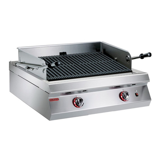
è stata progettata e costruita per la cottura tura è prodotta in più versioni (vedi figura). dei cibi a diretto contatto con la griglia, nell'ambito della ristorazione professionale. 090GRG 190GRG IDM-39616500100.tif Organi principali A)Griglia di cottura: è realizzata in ghisa. -
Page 7: Sicurezza
DATI TECNICI Vedi tabelle e “Scheda allacciamenti” in fondo al manuale. DISPOSITIVI DI SICUREZZA Anche se l'apparecchiatura è completa di tutti i di- spositivi di sicurezza, in fase di installazione e allac- ciamento essi dovranno, se necessario, essere integrati con altri in modo da rispettare le leggi vi- genti in materia. - Page 8 DOTAZIONE ACCESSORI Alla consegna viene fornita la seguente dotazione: A)Spazzola B)Prolunga scarico residui C)Supporto bacinella D)Bacinella di raccolta E)Maniglia sollevamento griglia IDM-39616500401.tif ACCESSORI A RICHIESTA A richiesta l'apparecchiatura può essere cor- redata dei seguenti accessori. A)Kit trasformazione gas B)Kit per installazione "su vano" (vedi pag. 18) C)Kit per installazione "a ponte"...
-
Page 9: Uso E Funzionamento
Tutti gli interventi di manutenzione che richiedono Alla fine di ogni utilizzo, assicurarsi che i bruciatori una precisa competenza tecnica o particolari capa- siano spenti, con le manopole comando disattivate cità devono essere eseguiti esclusivamente da per- e le linee di alimentazione scollegate. sonale qualificato, con esperienza riconosciuta e In caso di inattività... - Page 10 DESCRIZIONE COMANDI Sull'apparecchiatura sono disposti i comandi per at- B)Pulsante accensione: serve per accendere la tivare le funzioni principali. spia pilota dei bruciatori. A)Manopola comando bruciatore: per accende- re, spegnere e regolare il relativo bruciatore e spia pilota. Indice spegnimento Indice spia pilota Indice potenza massima Indice potenza minima...
- Page 11 MONTAGGIO PROLUNGA SCARICO RESIDUI Per questa operazione procedere nel modo indicato. 1 - Chiudere il rubinetto alimentazione gas. 2 - Sfilare le manopole (A). 3 - Svitare le viti (B) e smontare il cruscotto (C). 4 - Inserire la prolunga scarico residui (D) nel tubo di scarico (E) e fissarlo con il dado (F).
- Page 12 Montaggio guida su telaio di appoggio 4 - Montare la guida bacinella (A) con le viti (B) ed inserire la bacinella di raccolta (C). IDM-39616103100.tif Montaggio guida su trave di sostegno 5 - Montare il "Kit copertura top" (D). 6 - Montare la guida bacinella (A) con le viti (B) ed inserire la bacinella di raccolta (C).
-
Page 13: Manutenzioni
INATTIVITÀ PROLUNGATA DELL’APPARECCHIATURA Se l'apparecchiatura rimane inattiva per un lungo 4 - Eseguire tutte le operazioni di manutenzione. tempo, procedere nel modo indicato. 5 - Ricoprire l'apparecchiatura con un involucro e 1 - Chiudere il rubinetto alimentazione gas. lasciare alcune fessure per la circolazione 2 - Pulire accuratamente l'apparecchiatura e le dell'aria. - Page 14 PULIZIA APPARECCHIATURA Se si considera che l'apparecchiatura è utilizzata 3 - Pulire gli accessori dopo l'uso, con uno sgras- per la preparazione di prodotti alimentari per l'uo- sante idoneo. Si consiglia il lavaggio in lavasto- mo, è necessario prestare particolare cura a tutto viglie.
- Page 15 6 - Smontare il supporto griglia (C). 7 - Smontare il telaio paraspruzzi (D) e pulirlo. IDM-39616502200.tif 8 - Servirsi della maniglia (E), fornita a corredo, per Importante sollevare e capovolgere la griglia focolaio (F). Effettuare questa operazione giornalmente, per Non disperdere il contenuto della bacinella consentire la pulizia delle mattonelle da even- nell'ambiente, bensì...
- Page 16 PULIZIA BRUCIATORE Per questa operazione procedere nel modo indica- 1 - Asportare la griglia, il telaio paraspruzzi e la gri- glia focolaio (vedi pag. 12). 2 - Sollevare ed estrarre il bruciatore (A). 3 - Pulire accuratamente il bruciatore (A) e verifi- care che i suoi fori non siano ostruiti.
-
Page 17: Guasti
CONTROLLO PRESSIONE GAS Per questa operazione procedere nel modo indicato. 1 - Chiudere il rubinetto alimentazione gas. 2 - Sfilare le manopole (A). 3 - Svitare le viti (B) e smontare il cruscotto (C). 4 - Svitare la vite (D) della presa di pressione. 5 - Collegare il manometro (E) alla presa di pres- sione (F). -
Page 18: Movimentazione E Installazione
MOVIMENTAZIONE E INSTALLAZIONE RACCOMANDAZIONI PER LA MOVIMENTAZIONE E INSTALLAZIONE Importante Eseguire la movimentazione e l'installazio- ste operazioni dovrà, se necessario, orga- ne nel rispetto delle informazioni fornite dal nizzare “piano sicurezza” costruttore e riportate direttamente sull'im- salvaguardare l'incolumità delle persone ballo, sull'apparecchiatura e nelle istruzioni direttamente coinvolte. - Page 19 MOVIMENTAZIONE E SOLLEVAMENTO L'apparecchiatura può essere movimentata con un dispositivo di sollevamento a forche o a gancio di portata adeguata. Prima di effettuare questa opera- zione, controllare la posizione del baricentro del ca- rico. Importante Nell'inserire il dispositivo di sollevamento, fare attenzione al tubo di alimentazione gas.
- Page 20 MONTAGGIO APPARECCHIATURE IN BATTERIA Per montare le apparecchiature in batteria (fianco a fianco) procedere nel modo indicato. 1 - Sfilare le manopole (A). 2 - Svitare le viti (B) e smontare i cruscotti (C). 3 - Applicare, sui bordi da accostare, del nastro adesivo di protezione.
- Page 21 ALLACCIAMENTO GAS Importante Chi è autorizzato ad effettuare tale operazio- ne deve possedere capacità ed esperienza acquisita e riconosciuta nel settore specifico, dovrà eseguire l'allacciamento a regola d'arte e tenere conto di tutti i requisiti normativi e le- gislativi. Ad allacciamento completato, prima di rendere operativa l'attrezzatura, si dovrà...
- Page 22 5 - Rimontare il cruscotto (D) e le manopole (B) ad Importante operazione ultimata. In fase di allacciamento fare attenzione al collegamento dei cavi di neutro e di terra; se non è effettuato correttamente il brucia- tore non si accende. TRASFORMAZIONE ALIMENTAZIONE L'apparecchiatura è...
-
Page 23: Regolazioni
COLLAUDO APPARECCHIATURA 3 - Verificare la regolare accensione e combustione Importante del bruciatore. Prima della messa in servizio, deve essere 4 - Verificare il corretto funzionamento della termo- eseguito il collaudo dell'impianto, al fine di coppia di sicurezza. 5 - Verificare che non vi siano perdite di gas. valutare le condizioni operative di ogni sin- 6 - Verificare che le targhette siano compilate con le golo componente ed individuare le eventuali... -
Page 24: Sostituzione Parti
5 - Collegare il manometro (E) alla presa di pres- Gas liquido sione (F). Per questa operazione procedere nel modo indicato. 6 - Riaprire il rubinetto alimentazione gas. 1 - Chiudere il rubinetto alimentazione gas. 2 - Sfilare le manopole (A). 7 - Accendere il bruciatore e ruotare la manopola 3 - Svitare le viti (B) e smontare il cruscotto (C). - Page 25 SOSTITUZIONE UGELLO BRUCIATORE Per questa operazione procedere nel modo indica- 1 - Chiudere il rubinetto alimentazione gas. 2 - Sfilare le manopole (A). 3 - Svitare le viti (B) e smontare il cruscotto (C). 4 - Svitare l'ugello (D) e sostituirlo con quello adat- to al tipo di gas utilizzato (vedi tabella in fondo al manuale).
- Page 27 CONTENTS ref. chapters page 1 GENERAL INFORMATION ..........2 TECHNICAL INFORMATION ..........4 3 SAFETY ................6 PART 4 USE AND OPERATION ............. 7 5 SERVICING ..............11 6 FAULT ................15 7 HANDLING AND INSTALLATION ........16 8 ADJUSTMENTS ............... 21 9 REPLACING PARTS ............
-
Page 28: General Information
GENERAL INFORMATION INFORMATION FOR THE READER To find the specific topics of interest to you quickly, part: contains all the information neces- refer to the index at the start of the manual. sary for special categories of reader, i.e. all This manual is subdivided into two parts. - Page 29 IDENTIFICATION OF CONSTRUCTOR AND APPLIANCE ) Rated power (kW) The nameplate shown here is fitted directly to the ) Gas consumption appliance. It contains references and all essential ) Testing gas indicator frame information for operating safety. ) Voltage (V) Extra nameplate ) Frequency (Hz) ) Country of use...
-
Page 30: Technical Information
The appliance is produced in several versions to pliance, is designed and produced for cooking meet varying user requirements (see diagram). foods in direct contact with the griddle in the profes- sional catering sector. 090GRG 190GRG IDM-39616500100.tif Main Parts A)Cooking plate: in cast iron. - Page 31 TECHNICAL DATA See tables and "Connection chart" at the back of the manual. SAFETY DEVICES Although the appliance is complete with all safety devices, during installation and connection addi- tional devices must be added if necessary to com- ply with the relevant legal requirements. The illustration shows the position of the devices.
-
Page 32: Safety
STANDARD ACCESSORIES The appliance is delivered complete with the fol- lowing: A)Brush B)Residue drain extension. C)Drip tray support D)Drip tray E)Grill lifting handle IDM-39616500401.tif OPTIONAL ACCESSORIES The appliance can be equipped with the fol- lowing accessories on request. A)Gas conversion kit B)"Over cupboard"... -
Page 33: Use And Operation
To maintain hygiene and protect the food proc- In case of lengthy downtimes, as well as discon- essed from all forms of contamination, all elements necting all supply lines it is also essential to clean in direct or indirect contact with foodstuffs and all all internal and external parts of the appliance and surrounding zones must be cleaned thoroughly. - Page 34 DESCRIPTION OF CONTROLS The appliance is fitted with the controls for use of its regulating the relative burner and pilot light. main functions. B)Ignition button: lights the burner pilot light. A)Burner control knob: for lighting, turning off and Off marker Pilot light marker Full power marker Minimum power marker...
- Page 35 FITTING THE RESIDUE DRAIN EXTENSION To carry out this operation, proceed as follows. 1 - Turn off the gas supply tap. 2 - Pull off the knob (A). 3 - Undo the screws (B) and remove the control panel (C). 4 - Fit the residue drain extension (D) into the drain pipe (E) and secure it with the nut (F).
- Page 36 Fitting the runner on a supporting frame 4 - Fit the drip tray runner (A) with the screws (B) and insert the drip tray (C). IDM-39616103100.tif Fitting the runner on a supporting beam 5 - Fit the "griddle cover kit" (D). 6 - Fit the drip tray runner (A) with the screws (B) and insert the drip tray (C).
-
Page 37: Servicing
LENGTHY DOWNTIMES OF APPLIANCE If the appliance is to be out of use for a lengthy pe- 3 - Spread a film of edible oil over the stainless riod, proceed as follows. steel surfaces. 1 - Turn off the gas supply tap. 4 - Carry out all the servicing procedures. - Page 38 CLEANING INSTRUCTIONS Since the appliance is used for preparing foods for Caution - warning human consumption, special care must be paid to Never use products containing substances everything relating to hygiene, and the appliance harmful or hazardous for health (solvents, pe- and the entire surrounding environment must con- troleum spirits, etc.).
- Page 39 6 - Remove the grill support (C). 7 - Remove the splash guard frame (D) and clean IDM-39616502200.tif 8 - Use the handle (E) supplied to raise and over- Important turn the stone frame (F). Do this every day to al- low residue to be burnt off the ceramic bricks.
- Page 40 CLEANING THE BURNER To carry out this operation, proceed as follows. 1 - Remove the plate, the splashguard frame and the grid clearance reduction (see page 12). 2 - Lift and remove the burner (A). 3 - Clean the burner (A) and check that its holes are not blocked.
-
Page 41: Fault
CHECKING GAS PRESSURE To carry out this operation, proceed as follows. 1 - Turn off the gas supply tap. 2 - Pull off the knob (A). 3 - Undo the screws (B) and remove the control panel (C). 4 - Undo the screw (D) of the pressure connection. 5 - Connect the pressure gauge (E) to the pressure test point (F). -
Page 42: Handling And Installation
HANDLING AND INSTALLATION RECOMMENDATIONS FOR HANDLING AND INSTALLATION Important When handling and installing the appliance use. If necessary, the person authorised to comply with the information provided by carry out these operations must organise a the constructor directly on the packaging, "safety plan"... - Page 43 HANDLING AND LIFTING The appliance can be handled using fork-lift or hook equipment of suitable load-carrying capacity. Be- fore lifting, check the position of the load's centre of gravity. Important When engaging with the lifting equipment, watch out for the gas supply pipe. IDM-39603309300.tif INSTALLATION OF THE APPLIANCE All installation stages must be considered right from...
- Page 44 ASSEMBLY APPLIANCES IN BANKS To assemble appliances in banks (side by side) proceed as described below. 1 - Pull off the knob (A). 2 - Undo the screws (B) and remove the control panels (C). 3 - Apply masking tape to the edges to be placed side by side.
- Page 45 GAS CONNECTION Important Those authorised to carry out this opera- tion must have experience acquired and certified in the specific sector, must make the connection to the proper standards, and must comply with all the relevant regu- lations and legislation. Once the connec- tion has been made, before the appliance is put into operation a general check must be made to ensure there are no gas leaks.
- Page 46 5 - Replace the control panel (D) and the knobs (B) Important on completion of the operation. When connecting, take care over the con- nection of the neutral and earth wires; if they are not connected correctly, the burn- er does not light. CONVERSION OF GAS SUPPLY The constructor has tested the appliance with its own mains gas, identified by the sticker applied to...
-
Page 47: Adjustments
TESTING OF THE APPLIANCE and its combustion. Important 4 - Check that the safety thermocouple is working Before it is put into service, the system correctly. must be tested to check the operating con- 5 - Check that there are no gas leaks. 6 - Check that the nameplates specify the correct ditions of every single component and gas for the country of use. -
Page 48: Replacing Parts
5 - Connect the pressure gauge (E) to the pressure Liquid gas test point (F). To carry out this operation, proceed as follows. 6 - Turn the gas supply tap back on. 1 - Turn off the gas supply tap. 7 - Light the burner and turn the knob to the mini- 2 - Pull off the knob (A). - Page 49 REPLACEMENT OF THE BURNER NOZZLE To carry out this operation, proceed as follows. 1 - Turn off the gas supply tap. 2 - Pull off the knob (A). 3 - Undo the screws (B) and remove the control panel (C). 4 - Unscrew the nozzle (D) and replace it with the one suitable for the type of gas in use (see table at back of manual).
- Page 51 INHALTSVERZEICHNIS Ref. Kapitel Seite 1 ALLGEMEINES ..............2 2 TECHNISCHE INFORMATIONEN ........4 3 SICHERHEIT ..............6 1. TEIL 4 GEBRAUCH UND BETRIEB ..........7 5 WARTUNG ............... 11 6 DEFEKTE ................. 15 7 HANDHABUNG UND INSTALLATION ......16 8 EINSTELLUNGEN ............21 9 AUSTAUSCH VON BAUTEILE ........
-
Page 52: Allgemeines
ALLGEMEINES INFORMATIONEN FÜR DEN LESER Konsultieren Sie das Sachregister, das am Anfang 2. Teil: Diese Informationen wenden sich an des Handbuchs zu finden ist, um leichter unter be- eine bestimmte Zielgruppe. Sie sind für erfahre- stimmten Themen von besonderem Interesse ne Bediener bestimmt, die für Handhabung, nachschlagen zu können. - Page 53 TYPENSCHILD FÜR HERSTELLER UND GERÄT ) Angabe der Leistung (Kw) Das abgebildete Typenschild wird direkt auf dem ) Gasverbrauch Gerät aufgebracht. Es enthält sämtliche Angaben ) ITestgasanzeige und Hinweise, die für den sicheren Betrieb unerläs- ) Spannung (V) slich sind. ) Frequenz (Hz) Ergänzungsschild ) Benutzerland...
-
Page 54: Technische Informationen
Gerät bezeichnet wird, wurde für den Ge- Versionen hergestellt (siehe Abbildung). brauch in Restaurantbetrieben zum Braten von Speisen direkt auf der Platte projektiert und kon- struiert. 090GRG 190GRG IDM-39616500100.tif Hauptorgane A)Bratplatte: aus Gusseisen. B)Spritzschutzrahmen: zum Schutz gegen die beim Braten entstehenden Spritzer C)Geräterost: für die Halterung der Keramikeinsät-... - Page 55 TECHNISCHE DATEN Siehe Tabellen und „Anschlussschema" am Ende des Handbuchs. SICHERHEITSVORRICHTUNGEN Das Gerät wird zwar mit sämtlichen planmäßigen Sicherheitsvorrichtungen geliefert, es kann jedoch notwendig sein, während Installation und An- schluss ggf. weitere ergänzende Maßnahmen zu ergreifen, um den Anforderungen der einschlägi- gen geltenden Gesetze zu entsprechen.
-
Page 56: Sicherheit
ZUBEHÖRAUSSTATTUNG Bei der Übergabe wird folgende Ausstattung gelie- fert: A)Bürste B)Verlängerung zum Ablassen der Rückstände. C)Tragrahmen für Behälter D)Auffangbehälter E)Bratplatten-Hebegriff IDM-39616500401.tif OPTIONALES ZUBEHÖR Auf Wunsch kann das Gerät mit folgenden Zu- behörteilen ausgestattet werden. A)„Kit" zur Gasumstellung B)Einbausatz für die Montage auf Unter- schrank (siehe Seite 18) C)Einbausatz für Brückenmontage (siehe Seite 18) -
Page 57: Gebrauch Und Betrieb
Setzen Sie das Gerät nur für die vom Hersteller vor- Desinfektionsmitteln die von den Sicherheits- und gesehenen Verwendungszwecke ein. Gesundheitsschutzbestimmungen vorgeschriebe- missbräuchliche Einsatz des Geräts kann schwer- nen Körperschutzmittel tragen (Schutzhandschu- wiegende Gefahren für Sicherheit und Gesundheit he, Atemschutzmaske, Schutzbrille usw.). von Personen und finanzielle Verluste hervorrufen. - Page 58 BESCHREIBUNG DER BEDIENELEMENTE Das Gerät ist mit Bedienelementen zur Aktivierung B)Taste Zündung: Sie dient zum Zünden der der wichtigsten Funktionen ausgestattet. Zündflamme der Brenner. A)Bedienknebel Brenner: um den betreffenden Brenner zu zünden und einzustellen und den Zündflammenbrenner zu aktivieren Anzeige Anzeige Zündflam- Ausschaltung menbrenner...
- Page 59 MONTAGE DER VERLÄNGERUNG ZUM ABLASSEN DER RÜCKSTÄNDE Für diesen Vorgang in der angegebenen Weise verfahren. 1 - Schließen Sie den Gaszufuhrhahn 2 - Den Schalter (A) abziehen. 3 - Drehen Sie die Schrauben (B) heraus und montieren Sie die Blende (C) ab. 4 - Die Verlängerung zum Ablassen der Rückstän- de (D) in das Ablassrohr (E) stecken und mit der Mutter (F) befestigen.
- Page 60 Montage des Behältertragrahmens auf Stütz- rahmen 4 - Den Behältertragrahmen (A) mit den Schrau- ben (B) befestigen und den Auffangbehälter (C) einschieben. IDM-39616103100.tif Montage des Behältertragrahmens auf Trä- 6 - Den Behältertragrahmen (A) mit den Schrau- ben (B) befestigen und den Auffangbehälter (C) 5 - Den "Bausatz Abdeckung Oberseite"...
-
Page 61: Wartung
LÄNGERER STILLSTAND DES GERÄTS Verfahren Sie folgendermaßen, falls das Gerät län- 4 - Führen Sie sämtliche Wartungsarbeiten aus. gere Zeit nicht eingesetzt werden soll: 5 - Das Gerät mit einer Schutzhülle abdecken; 1 - Schließen Sie den Gaszufuhrhahn hierbei einige Öffnungen für die Luftzirkulation 2 - Reinigen Sie das Gerät und die angrenzenden lassen. - Page 62 REINIGUNG DES GERÄTS Da das Gerät zur Zubereitung von Speisen für den Vorsicht - Achtung Menschen eingesetzt wird, ist besondere Sorgfalt auf Verwenden Sie keine Produkte, die Stoffe ent- die Hygiene geboten. Das Gerät und dessen näheres halten, welche für die menschliche Gesund- Umfeld müssen konstant sauber gehalten werden.
- Page 63 6 - Die Bratplatten-Halterung (C) entnehmen 7 - Den Spritzschutzrahmen (D) abmontieren und reinigen. IDM-39616502200.tif 8 - Den mitgelieferten Hebegriff (E) verwenden, Wichtig um die Bratplatte (F) anzuheben und umzu- drehen. Den Inhalt des Auffangbehälters vorschrift- Diesen Vorgang täglich ausführen, um die Rei- smäßig entsprechend den im Benutzung- nigung der Keramikeinsätze von eventuellen sland geltenden Bestimmungen entsorgen.
- Page 64 REINIGUNG DES BRENNERS Für diesen Vorgang in der angegebenen Weise verfahren. 1 - Die Bratplatte, den Spritzschutzrahmen und den Geräterost entfernen (siehe Seite 12). 2 - Den Brenner (A) anheben und herausziehen. 3 - Den Brenner (A) gründlich reinigen und sicher- stellen, dass dessen Löcher nicht verstopft sind.
-
Page 65: Defekte
KONTROLLE DES GASDRUCKS Für diesen Vorgang in der angegebenen Weise verfahren. 1 - Schließen Sie den Gaszufuhrhahn 2 - Den Schalter (A) abziehen. 3 - Drehen Sie die Schrauben (B) heraus und montieren Sie die Blende (C) ab. 4 - Drehen Sie die Schrauben (D) aus dem Druck- prüfpunkt. -
Page 66: Handhabung Und Installation
HANDHABUNG UND INSTALLATION EMPFEHLUNGEN FÜR DIE INSTALLATION UND HANDHABUNG Wichtig Beachten Sie die Hinweise des Herstellers, nen autorisierte Person wird bei Bedarf die direkt auf der Verpackung, auf dem Ge- einen „Sicherheitsplan" aufstellen müssen, rät selbst oder in der Gebrauchsanweisung um die Unversehrtheit der direkt an dem zu finden sind, wenn Sie das Gerät handha- Vorgang beteiligten Personen zu gewähr-... - Page 67 HANDHABUNG UND HUB Das Gerät kann mit einem Hubmittel bewegt wer- den, das mit Gabeln oder Haken ausgestattet ist und die geeignete Traglast besitzt. Vor diesem Vor- gang ist der Schwerpunkt der Last zu überprüfen. Wichtig Achten Sie beim Einsatz des Hubmittels auf das Gaszufuhrrohr.
- Page 68 MONTAGE BEI REIHENAUFSTELLUNG Verfahren Sie folgendermaßen, um Geräte (neben- einander) in einer Reihe aufzustellen. 1 - Den Schalter (A) abziehen. 2 - Die Schrauben (B) ausschrauben und die Blen- den (C) ausbauen. 3 - Bekleben Sie die Gerätekanten, die nebenein- ander angeordnet werden sollen, mit einem Schutzband.
- Page 69 GASANSCHLUSS Wichtig Diese Arbeit darf nur von zugelassenen und erfahrenen Fachleuten ausgeführt wer- den. Der Anschluss muss fachgerecht und vorschriftsmäßig ausgeführt werden und allen einschlägigen gesetzlichen Bestim- mungen entsprechen. Nach Ausführung des Anschlusses muss vor der Inbetrieb- nahme des Geräts durch eine allgemeine Kontrolle sichergestellt werden, dass nir- IDM-39616502000.tif gends Gas austritt.
- Page 70 5 - Abschließend die Bedienblende (D) und die Wichtig Schalter (B) wieder anbringen. Bei der Ausführung des Anschlusses auf den Anschluss des Neutral- und des Schutzleiters achten. Wenn diese An- schlüsse nicht richtig ausgeführt werden, kann der Brenner nicht gezündet werden. UMSTELLUNG DER GASVERSORGUNG Der werkseitig durchgeführte Testlauf ist mit dem Gastyp des örtlichen Gaswerks durchgeführt worden.
-
Page 71: Einstellungen
TESTLAUF ZUR ABNAHME DES GERÄTS 3 - Sicherstellen, dass Zündung und Verbrennung Wichtig beim Brenner ordnungsgemäß funktionieren. 4 - Überprüfen Sie die einwandfreie Funktionsfä- Vor der Inbetriebnahme muss ein Testlauf higkeit des Sicherheits- Thermoelements. der Anlage durchgeführt werden, um den 5 - Stellen Sie sicher, dass kein Gas austritt. -
Page 72: Austausch Von Bauteile
5 - Schließen Sie das Manometer (E) an den 13 - Abschließend die Bedienblende (C) und die Druckprüfpunkt (F) an. Schalter (A) wieder anbringen. 6 - Den Gasabsperrhahn wieder öffnen. Flüssiggas 7 - Zünden Sie den Brenner an und drehen Sie Für diesen Vorgang in der angegebenen Weise den Bedienknebel bis in die Position der mini- verfahren. - Page 73 AUSWECHSELN DER BRENNERDÜSE Für diesen Vorgang in der angegebenen Weise verfahren. 1 - Schließen Sie den Gaszufuhrhahn 2 - Den Schalter (A) abziehen. 3 - Drehen Sie die Schrauben (B) heraus und montieren Sie die Blende (C) ab. 4 - Schrauben Sie die Düse (D) heraus und erset- zen Sie sie mit dem für den betreffenden Gas- typ geeigneten Ersatzteil (siehe Tabelle am Ende des Handbuches).
- Page 75 INDEX réf. chapitres page 1 INFORMATIONS GÉNÉRALES ......... 2 2 INFORMATIONS TECHNIQUES ........4 3 SÉCURITÉ ................. 6 PARTIE 4 UTILISATION ET FONCTIONNEMENT ......7 5 ENTRETIEN ..............11 6 PANNES ................15 7 MANUTENTION ET INSTALLATION ....... 16 8 RÉGLAGES ..............21 9 REMPLACEMENT DE PIÈCES ........
- Page 76 INFORMATIONS GÉNÉRALES INFORMATIONS POUR LE LECTEUR Pour retrouver facilement les sujets qui vous inté- partie: elle contient toutes les informations ressent, consulter l’index analytique au début du nécessaires aux destinataires homogènes, manuel. c’est-à-dire tous les opérateurs experts et Ce manuel est divisé en deux parties. autorisés à...
- Page 77 IDENTIFICATION DU FABRICANT ET DE L’APPAREIL ) Puissance déclarée (kW) La plaque d’identification représentée, est appli- ) Consommation de gaz quée directement sur l'appareil. Elle reporte les ré- ) Indicateur du gaz d’essai férences et les indications indispensables à la ) Tension (V) sécurité.
- Page 78 été conçue et fabriquée pour la cuisson d'aliments est réalisé en plusieurs versions (voir figure). en contact direct avec la plaque de cuisson, dans le domaine de la restauration professionnelle. 090GRG 190GRG IDM-39616500100.tif Organes principaux A)Plaque de cuisson : en fonte.
- Page 79 DONNÉES TECHNIQUES Voir tableaux et « Fiche des raccordements » à la fin du manuel. DISPOSITIFS DE SÉCURITÉ Même si l’appareil est complet de tous les disposi- tifs de sécurité, lors de l’installation et du raccorde- ment, ils devront, si nécessaire, être intégrés avec d’autres pour respecter les lois en vigueur.
- Page 80 DOTATION D’ACCESSOIRES À la livraison sont fournis en équipement : A)Brosse B)Rallonge évacuation des résidus C)Support du bac D)Bac de récolte E)Poignée de levage de la grille IDM-39616500401.tif ACCESSOIRES SUR DEMANDE Sur demande l'appareil peut être équipé des accessoires suivants. A)«...
- Page 81 Tous les entretiens qui demandent une compéten- À la fin de chaque utilisation, s’assurer que les brû- ce technique précise ou des capacités particulières leurs sont éteints, avec les manettes de commande ne peuvent être exécutés que par du personnel désactivées et les lignes d’alimentation interrom- qualifié, ayant une expérience reconnue et acquise pues.
- Page 82 DESCRIPTION DES COMMANDES Sur l’appareil sont disposées les commandes pour B)Bouton d'allumage : pour allumer la veilleuse activer les fonctions principales. pilote des brûleurs. A)Manette de commande du brûleur : pour allu- mer, éteindre et régler le brûleur correspondant et la veilleuse pilote Index extinction Index veilleuse pilote Index puissance maximum...
- Page 83 MONTAGE DE LA RALLONGE ÉVACUATION DES RÉSIDUS Pour cette opération, procéder comme suit. 1 - Fermer le robinet d’alimentation du gaz. 2 - Enlever la manette (A). 3 - Dévisser les vis (B) et démonter le tableau de commandes (C). 4 - Enfiler la rallonge évacuation des résidus (D) dans le tuyau d’évacuation (E) et fixer avec l’écrou (F).
- Page 84 Montage du guide sur le bâti d’appui 4 - Monter le guide du bac (A) avec les vis (B) et introduire le bac de récolte (C). IDM-39616103100.tif Montage du guide sur la traverse de sou- tien 5 - Monter le « Kit de couverture du dessus » (D). 6 - Monter le guide du bac (A) avec les vis (B) et introduire le bac de récolte (C).
- Page 85 INUTILISATION PROLONGÉE DE L’APPAREIL Si l'appareil reste inactif pendant longtemps, procé- 3 - Étaler un voile d’huile alimentaire sur les surfa- der comme suit. ces en acier inox. 1 - Fermer le robinet d’alimentation du gaz. 4 - Exécuter toutes les opérations d’entretien. 2 - Nettoyer soigneusement l'appareil et les zones 5 - Recouvrir l'appareil d'une protection et laisser limitrophes...
- Page 86 NETTOYAGE DE L’APPAREIL Étant donné que l'appareil est utilisé pour la prépa- sation avec un dégraissant approprié. Le lava- ration de produits alimentaires pour l'homme, il faut ge en lave-vaisselle est conseillé. faire attention à tout ce qui concerne l'hygiène; l'ap- Attention pareil et tout ce qui l'entoure doivent toujours être Ne pas utiliser de produits qui contiennent...
- Page 87 6 - Démonter le support de la grille (C). 7 - Démonter les pare-éclaboussures (D) et les nettoyer. IDM-39616502200.tif 8 - Se servir de la poignée (E), fournie en équipe- Important ment, pour lever et retourner la grille du foyer (F).
- Page 88 NETTOYAGE DU BRÛLEUR Pour cette opération, procéder comme suit. 1 - Retirer la plaque, les pare-éclaboussures et la grille de réduction (voir page 12). 2 - Lever et extraire le brûleur (A). 3 - Nettoyer soigneusement le brûleur (A) et véri- fier que ses trous ne soient pas obstrués.
- Page 89 CONTRÔLE DE LA PRESSION DU GAZ Pour cette opération, procéder comme suit. 1 - Fermer le robinet d’alimentation du gaz. 2 - Enlever la manette (A). 3 - Dévisser les vis (B) et démonter le tableau de commandes (C). 4 - Dévisser la vis (D) de la prise de pression. 5 - Raccorder le manomètre (E) à...
- Page 90 MANUTENTION ET INSTALLATION RECOMMANDATIONS POUR LA MANUTENTION ET L’INSTALLATION Important Effectuer la manutention et l’installation en effectuer ces opérations devra, si nécessai- respectant les informations fournies par le re, organiser un « plan de sécurité » pour fabricant, reportées directement sur l’em- sauvegarder la sécurité...
- Page 91 MANUTENTION ET LEVAGE L'appareil peut être manutentionné avec un dispo- sitif de levage à fourches ou à crochet d’une capa- cité de charge appropriée. Avant d’effectuer cette opération, contrôler la position du centre de gravité de la charge. Important En introduisant le dispositif de levage, faire attention au tuyau d’alimentation du gaz.
- Page 92 MONTAGE DES APPAREILS EN BATTERIE Pour monter les appareils en batterie (les uns à côté des autres), procéder comme suit. 1 - Enlever la manette (A). 2 - Dévisser les vis (B) et démonter les tableaux de commandes (C). 3 - Appliquer, sur les bords à rapprocher, du ruban adhésif de protection.
- Page 93 RACCORDEMENT DU GAZ Important La personne autorisée à effectuer cette opération devra avoir les capacités et l'ex- périence acquise et reconnue dans le sec- teur spécifique; elle devra effectuer le raccordement dans les règles de l'art et te- nir compte de toutes les exigences impo- sées par les normes et les lois.
- Page 94 5 - Remonter le tableau de commandes (D) et les Important manettes (B) lorsque l’opération est terminée. Au moment du branchement, faire attention à la connexion des câbles de neutre et de terre ; si elle n'est pas effectuée correcte- ment, le brûleur ne s'allume pas.
- Page 95 ESSAI DE L’APPAREIL 3 - Vérifier l'allumage régulier et la combustion du Important brûleur. Avant la mise en service, l’essai de l’instal- 4 - Vérifier le fonctionnement correct du thermo- lation doit être fait pour évaluer les condi- couple de sécurité. 5 - Vérifier qu’il n’y ait pas de fuites de gaz.
- Page 96 5 - Raccorder le manomètre (E) à la prise de pres- Gaz liquide sion (F). Pour cette opération, procéder comme suit. 6 - Rouvrir le robinet d’alimentation du gaz. 14 - Fermer le robinet d’alimentation du gaz. 7 - Allumer le brûleur et tourner la manette sur la 15 - Enlever la manette (A).
- Page 97 REMPLACEMENT DE LA BUSE DU BRÛLEUR Pour cette opération, procéder comme suit. 1 - Fermer le robinet d’alimentation du gaz. 2 - Enlever la manette (A). 3 - Dévisser les vis (B) et démonter le tableau de commandes (C). 4 - Dévisser la buse (D) et la remplacer par celle adaptée au type de gaz utilisé...
- Page 99 ÍNDICE ref. capítulos pág 1 INFORMACIONES DE CARÁCTER GENERAL ....2 2 INFORMACIONES DE CARÁCTER TÉCNICO ....4 3 SEGURIDAD ..............6 PARTE 4 USO Y FUNCIONAMIENTO ..........7 5 MANTENIMIENTO ............11 6 AVERÍAS ................15 7 DESPLAZAMIENTO E INSTALACIÓN ......16 8 REGULACIONES .............
-
Page 100: Informaciones De Carácter General
INFORMACIONES DE CARÁCTER GENERAL INFORMACIONES PREVIAS Para ubicar fácilmente los temas específicos de in- parte: contiene todas las informaciones ne- terés, consúltese el índice analítico que se encuen- cesarias para destinatarios homogéneos, esto tra al inicio del manual. es, todos los operadores expertos y autoriza- Este manual comprende dos partes. - Page 101 IDENTIFICACIÓN FABRICANTE Y EQUIPO ) Potencia declarada (kW) La placa de identificación fijada directamente en el ) Consumo de gas equipo reproduce todas las referencias e indicacio- ) Indicador gas prueba de funcionamiento nes indispensables para la seguridad de servicio. ) Tensión (V) Placa complementaria ) Frecuencia (Hz)
-
Page 102: Informaciones De Carácter Técnico
(véa- para cocer alimentos mediante contacto directo con se figura). la parrilla misma, en el sector de la restauración profesional. 090GRG 190GRG IDM-39616500100.tif Órganos principales A)Parrilla de cocción: realizada en fundición. B)Bastidor de protección contra las salpicadu- ras: para proteger contra las salpicaduras pro- pias de la cocción... -
Page 103: Seguridad
DATOS TÉCNICOS Véase tablas y "Ficha de enlaces" al final del ma- nual. DISPOSITIVOS DE SEGURIDAD Aunque el equipo cuente con todos los dispositivos de seguridad, en los casos en que así lo determi- nen las leyes vigentes en materia, se deberá com- plementar con otros dispositivos en las fases de instalación y enlace. - Page 104 DOTACIÓN DE ACCESORIOS El aparato se suministra equipado con los siguien- tes elementos: A)Cepillo B)Alargador de evacuación residuos C)Soporte cubeta D)Cubeta de recogida E)Manija de elevación rejilla IDM-39616500401.tif ACCESORIOS BAJO PEDIDO Bajo pedido, el equipo puede ser suministrado con los accesorios que a continuación se indi- can.
-
Page 105: Uso Y Funcionamiento
sar riesgos en cuanto a seguridad y salud de las sitivos de protección individual (guantes, mascari- personas, además de daños económicos. llas, gafas, etc.), en conformidad con lo dispuesto por las leyes vigentes sobre seguridad y salud. Todas las intervenciones de mantenimiento que re- quieren de una competencia técnica precisa o de Al final de cada utilización, controlar que los que- una capacidad especial, deben ser efectuadas ex-... - Page 106 DESCRIPCIÓN DE LOS MANDOS Para activar las funciones principales, en el equipo B)Botón de encendido: para encender el testigo se han instalado los siguientes mandos. piloto de los quemadores. A)Mando quemador: para encender, apagar y re- gular el respectivo quemador y testigo piloto Índice apagado Índice testigo piloto Índice potencia máxima...
- Page 107 MONTAJE ALARGADOR DESCARGA RESIDUOS Para efectuar esta operación, aplicar las siguientes instrucciones. 1 - Cerrar el grifo de alimentación del gas. 2 - Retirar el mando (A). 3 - Desenroscar los tornillos (B) y desmontar el ta- blero de instrumentos (C). 4 - Conectar el alargador de evacuación residuos (D) en el tubo de evacuación (E) y fijarlo me- diante la tuerca (F).
- Page 108 Montaje guía en bastidor de apoyo 4 - Montar la guía cubeta (A) mediante los tornillos (B) e instalar la cubeta de recogida (C). IDM-39616103100.tif Montaje guía en barra de soporte 5 - Montar el "Kit cobertura top" (D). 6 - Montar la guía cubeta (A) mediante los tornillos (B) e instalar la cubeta de recogida (C).
-
Page 109: Mantenimiento
PERÍODO PROLONGADO DE INACTIVIDAD DEL EQUIPO En caso de que el equipo deba permanecer inacti- 4 - Efectuar todas las operaciones de manteni- vo durante un período prolongado de tiempo, se miento. deberán efectuar las siguientes operaciones. 5 - Cubrir el aparato con una envoltura de protec- 1 - Cerrar el grifo de alimentación del gas. - Page 110 LIMPIEZA APARATO Atendida la circunstancia de que el equipo es utili- 3 - Limpiar los accesorios después del uso utili- zado para la preparación de productos alimenticios zando un desengrasante adecuado. Se acon- para el consumo humano, es necesario prestar es- seja efectuar el lavado en lavavajillas.
- Page 111 6 - Desmontar el soporte de la rejilla (C). 7 - Desmontar y limpiar el bastidor de protección contra salpicaduras (D). IDM-39616502200.tif 8 - Utilizar la manija (E), suministrada adjunta, Importante para elevar e invertir la rejilla hogar (F). Esta operación debe efectuarse diariamente a No derramar el contenido de la cubeta en el fin de mantener limpios los azulejos, evitando ambiente.
- Page 112 LIMPIEZA QUEMADOR Para efectuar esta operación, aplicar las siguientes instrucciones. 1 - Retirar la parrilla, el bastidor de protección contra salpicaduras y la rejilla hogar (véase pág. 12). 2 - Levantar y extraiga el quemador (A). 3 - Limpiar esmeradamente el quemador (A) y ve- rificar que sus agujeros no estén obstruidos.
-
Page 113: Averías
CONTROL DE LA PRESIÓN DEL GAS Para efectuar esta operación, aplicar las siguientes instrucciones. 1 - Cerrar el grifo de alimentación del gas. 2 - Retirar el mando (A). 3 - Desenroscar los tornillos (B) y desmontar el ta- blero de instrumentos (C). 4 - Desenroscar el tornillo (D) de la toma de presión. -
Page 114: Desplazamiento E Instalación
DESPLAZAMIENTO E INSTALACIÓN RECOMENDACIONES PARA EL DESPLAZAMIENTO Y LA INSTALACIÓN Importante Efectuar el desplazamiento e instalación rizada para efectuar estas operaciones de- respetando las indicaciones proporciona- berá, si fuera necesario, organizar un "plan das por el fabricante, reproducidas directa- de seguridad", a fin de salvaguardar la in- mente sobre el embalaje, en el equipo y en columidad de las personas directamente las instrucciones de uso. - Page 115 DESPLAZAMIENTO Y ELEVACIÓN El equipo puede ser desplazado con un equipo de elevación de horquillas o de gancho, de capacidad adecuada. Para ejecutar esta operación se debe controlar atentamente el centro de gravedad de la carga. Importante Proceder con cautela al introducir el equipo de elevación a fin de no dañar el tubo de ali- mentación del gas.
- Page 116 MONTAJE DE EQUIPOS EN BATERÍA Para montar los equipos en batería (uno al lado del otro) aplicar las siguientes instrucciones. 1 - Retirar el mando (A). 2 - Desenroscar los tornillos (B) y desmontar los paneles de mando (C). 3 - Poner cinta adhesiva de protección sobre los bordes a juntar.
- Page 117 ENLACE GAS Importante El personal autorizado para ejecutar esta operación debe poseer capacidad y haber adquirido experiencia efectiva en el sector específico; la conexión deberá ejecutarse respetando rigurosamente todos los requi- sitos establecidos por las normativas vi- gentes. Una vez efectuada la conexión, antes de poner en funcionamiento el apara- to se deberá...
- Page 118 5 - Una vez concluida la operación, reinstalar el Importante panel de mandos (D) y los mandos (B). Durante las operaciones de enlace se debe- rá prestar especial atención a la conexión de los cables de neutro y de tierra ya que, en caso de no ser correctamente efectuada, el quemador no se encenderá.
-
Page 119: Regulaciones
PRUEBA DE FUNCIONAMIENTO DEL EQUIPO pág. 20). Importante 3 - Controlar el correcto encendido y combustión Antes de la puesta en servicio debe efec- del quemador. tuarse la prueba de funcionamiento del sis- 4 - Controlar el perfecto funcionamiento del termo- par de seguridad. -
Page 120: Sostitución De Piezas
4 - Desenroscar el tornillo (D) de la toma de presión. Gas líquido 5 - Conectar el manómetro (E) a la toma de pre- Para efectuar esta operación, aplicar las siguientes sión (F). instrucciones. 6 - Volver a abrir la llave de alimentación del gas. 14 - Cerrar el grifo de alimentación del gas. - Page 121 SUSTITUCIÓN INYECTOR QUEMADOR Para efectuar esta operación, aplicar las siguientes instrucciones. 1 - Cerrar el grifo de alimentación del gas. 2 - Retirar el mando (A). 3 - Desenroscar los tornillos (B) y desmontar el ta- blero de instrumentos (C). 4 - Desenroscar el inyector (D) y sustituirlo por otro que sea adecuado para el tipo de gas utilizado (véase tabla al final del manual).
- Page 123 (Min. 4,5 kW) G25.1 2W / 230V1~N 090GRG N. 1 0,95 m /h 1,11 m 0,71 Kg/h 0,70 Kg/h 50/60 Hz SCHEDA ALLACCIAMENTI (090GRG) - CONNECTION CARD (090GRG) ANSCHLUSSSCHEMA (090GRG) - FICHE DES RACCORDEMENTS (090GRG) FICHA DE ENLACES (090GRG) IDM-39616501800.tif...
- Page 124 Bruciatore Consumo gas Allacciamento elettrico Burner - Brenner Gas consumption - Gasverbrauch Modello Electrical connection Consommation de gaz - Consumo de gas Bruleur - Quemadores Model - Modelle Stromanschluss Modèle - Modelo Branchement électrique 9 kW Conexión eléctrica (Min. 4,5 kW) G25.1 2W / 230V1~N 190GRG...
- Page 125 SCHEMA ELETTRICO (090GRG) - ELECTRICAL SYSTEM DIAGRAM (090GRG) ELEKTRISCHER SCHALTPLAN (090GRG) - SCHÉMA ÉLECTRIQUE (090GRG) ESQUEMA ELÉCTRICO (090GRG) IDM-39614701800.tif 1) Morsettiera - Terminal board - Klemmenbrett - Plaque à bornes - Regleta de 3) Gruppo accensione - Ignition unit - Baugruppe Zündung - Groupe d’allumage conexión...
- Page 126 SCHEMA ELETTRICO (190GRG) - ELECTRICAL SYSTEM DIAGRAM (190GRG) ELEKTRISCHER SCHALTPLAN (190GRG) - SCHÉMA ÉLECTRIQUE (190GRG) ESQUEMA ELÉCTRICO (190GRG) IDM-39614701900.tif 4) Candeletta sinistra - Left plug - Linke Zündkerze - Bougie gauche - Bujía 1) Morsettiera - Terminal board - Klemmenbrett - Plaque à bornes - Regleta de izquierda conexión 5) Candeletta destra - Right plug - Rechte Zündkerze - Bougie droit - Bujía...
- Page 127 Tabella iniettori bruciatore - Burner injector table - Tabelle der Brennerdüsen Tableau des injecteurs des brûleurs - Tabla inyectores quemador pen mbar Qn max p (3) mbar ø (4) ø (5) ø (6) Qn min p (7) mbar ø (8) G30/G31 AT II2H3B/P G30/G31...
- Page 128 Tabella iniettori bruciatore - Burner injector table - Tabelle der Brennerdüsen Tableau des injecteurs des brûleurs - Tabla inyectores quemador ø (8) pen mbar Qn max p (3) mbar ø (4) ø (5) ø (6) Qn min p (7) mbar G30/G31 LV II2H3B/P G30/G31...
- Page 129 Tabella caratteristiche gas - Table of gas characteristics - Tabelle der Gas-Eigenschaften Tableau des caractéristiques du gaz - Tabla características gas Potere calorifero inferiore (Hi) Famiglia Tipo di gas Indice Wobbe (MJ/m Net calorific value (Hi) Group Gas type Wobbe index (MJ/m Unterer Heizwert (Hi) Familie Gastypen...
Need help?
Do you have a question about the 090GRG and is the answer not in the manual?
Questions and answers