Table of Contents
Advertisement
Quick Links
Advertisement
Table of Contents

Subscribe to Our Youtube Channel
Related Manuals for Angelo Po 1G1BR1G


Summary of Contents for Angelo Po 1G1BR1G
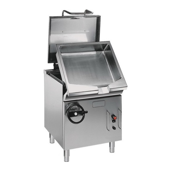
- Page 1 GAS BRATT PAN 1G1BR1G USE AND INSTALLATION MANUAL 3014080...
- Page 2 Contact for Sales or Service: Angelo Po Catering Equipment Unit 4, 15-17 Heatherdale Road. Ringwood, Victoria 3134. Telephone: (03) 9874 0440 Facsimile: (03) 9874 0330...
-
Page 3: Table Of Contents
CONTENTS ref. chapters page 0 INFORMATION FOR THE READER ........2 1 GENERAL INFORMATION ..........2 2 TECHNICAL INFORMATION ..........3 3 SAFETY ................5 PART 4 USE AND OPERATION ............5 5 SERVICING ................ 8 6 FAULT ................. 9 7 HANDLING AND INSTALLATION........ -
Page 4: Information For The Reader
INFORMATION FOR THE READER To find the specific topics of interest to you quickly, re- part: contains all the information necessary fer to the index at the start of the manual. for special categories of reader, i.e. all skilled op- This manual is subdivided into two parts. -
Page 5: Technical Information
Gas data Manifacture s data 1a) Gas type Serial number 1b) Test point pressure Test gas indicator frame 1c) Nominal gas consumption Application Model Country Personalization PROCEDURE FOR REQUESTING SERVICE Contact one of the authorised service centres for all When requesting service, state the data provide on requirements. - Page 6 SAFETY DEVICES Although the appliance is complete with all safety de- vices, during installation and connection additional devices must be added if necessary to comply with the relevant legal requirements. The illustration shows the position of the devices. A)Gas supply tap: for turning the connection to the gas supply line on and off.
-
Page 7: Safety
SAFETY SAFETY REGULATIONS During design and construction, the constructor has Use the appliance only for the functions intended by the paid special attention to factors which may cause manufacturer. Improper use of the appliance may in- risks to the health and safety of the people interacting volve health and safety risks and economic losses. - Page 8 DESCRIPTION OF CONTROLS Pilot light Temperature marker Piezoelectric ignition marker marker Off marker Pilot light marker IDM-39604005100.tif The appliance is fitted with the controls for use of its B)Pilot light ignition button. main functions. C)Pilot light switch-off button. A)Burner control knob: for lighting, turning off D)Piezoelectric ignition knob: for lighting the pilot and regulating the relative burner and pilot light.
- Page 9 DRAINING THE WELL To carry out this operation, proceed as follows. 1 - Turn off the gas supply tap; 2 - Raise the lid (A). 3 - Turn handle B clockwise to tilt the well for empty- ing. Important Never force the well, as this may damage the tilting mechanism.
-
Page 10: Servicing
SERVICING RECOMMENDATIONS FOR SERVICING Keep the appliance at peak efficiency by carrying out the well;; the scheduled servicing procedures recommended the burner; by the constructor. Proper servicing will allow the best the appliance and the surrounding environment performance, a longer working life and constant (see page 8). -
Page 11: Fault
CHECKING GAS PRESSURE To carry out this operation, proceed as follows. 1 - Turn off the gas supply tap. 2 - Pull off knob (A) and dis- assemble handle (B). 3 - Undo the screws (C) and remove panel (D). 4 - Undo the screw (E) of the pressure connection. -
Page 12: Handling And Installation
HANDLING AND INSTALLATION RECOMMENDATIONS FOR HANDLING AND INSTALLATION Important When handling and installing the appliance If necessary, the person authorised to carry comply with the information provided by out these operations must organise a "safe- the constructor directly on the packaging, ty plan"... - Page 13 INSTALLATION OF THE APPLIANCE All installation stages must be considered right from pro- duction of the general layout. Before starting these stag- es, as well as deciding the place of installation, if necessary, the person authorised to carry out these op- erations must organise a "safety plan"...
- Page 14 INSTALLATION OF THE FLUE DEFLECTOR 1 - Insert the pivots (1) and (2) both in the holes Fig. A of the deflector (5) and in the upper holes of the flue (8) (see Fig.A). 2 - Fix the pivots (1) and (2) by means of nuts (6) and washer (7).
- Page 15 GAS CONNECTION To make the connection, connect the mains line to the appliance's connection pipe, fitting a shut-off tap (A), to allow the gas supply to be cut off when neces- sary. Important The tap (A), not supplied with the appliance, must be installed in an easily accessible position and its status (on or off) must be obvious at a glance.This appliance shall be...
-
Page 16: Adjustments
TESTING OF THE APPLIANCE 3 - check that the burner is switching on correctly and Important its combustion; 4 - check the gas pressure and flow-rate at minimum Before it is put into service, the system must and maximum settings and adjust if necessary be tested to check the operating conditions (see page 14);... - Page 17 Natural gas In this case the gas pressure upstream of the nozzle has to be adjusted; proceed as fol- lows. 1 - Fill the well with 10 litres of water. 2 - Turn off the gas supply tap. 3 - Pull off knob (A) and dis- assemble handle (B).
-
Page 18: Replacing Parts
REPLACING PARTS RECOMMENDATIONS FOR REPLACING PARTS Before carrying out any replacement procedure, acti- The manufacturer declines all responsibly for injury or vate all the safety devices provided and decide damage to components due to the use of non original whether staff at work and those in the vicinity should parts, or extraordinary work on the appliance which be informed. - Page 19 REPLACEMENT OF THE PILOT LIGHT INJECTOR To carry out this operation, proceed as follows. 1 - Turn off the gas supply tap. 2 - Pull off knob (A) and dis- assemble handle (B). 3 - Undo the screws (C) and remove panel (D).
-
Page 20: Annexes
- ANNEXES - Total Gas consumption - Burner - Model ULPG 1G1BR1G N. 1 48 MJ/h 39 MJ/h - CONNECTION CARD - IDM-39604006100_1.tif... - Page 21 N.G.C. (2) T.G.C. (3) Pilot Flame Bushing Ø TPP (1) G.C. Ø (3.1) p (3.2) Ø (4) Ø (5) (2.3) (2.1) (2.2) adj-pressure 48 Mj/h <1 Mj/h 3.30mm 28 MJ/h 1.70 mm 0.40 mm 16 mm 0.8 kPa 0.30 kPa 39 Mj/h <...
Need help?
Do you have a question about the 1G1BR1G and is the answer not in the manual?
Questions and answers