Table of Contents
Advertisement
Available languages
Available languages
Quick Links
BAGNOMARIA "GAS"
"GAS" BAIN-MARIE
GAS-BAINMARIE
BAIN MARIE "GAZ"
BAÑOMARÍA "GAS"
MANUALE D'USO E INSTALLAZIONE
BEDIEN- UND INSTALLATIONSHANDBUCH
MANUEL D'UTILISATION ET D'INSTALLATION
USE AND INSTALLATION MANUAL
MANUAL DE USO E INSTALACIÓN
090BM1G
190BM2G
Italiano
English
Deutsch
Français
Español
Ed.2
12/2010
3071700
IT
GB
DE
FR
ES
Advertisement
Chapters
Table of Contents

Related Manuals for Angelo Po 090BM1G


Summary of Contents for Angelo Po 090BM1G
- Page 1 BAGNOMARIA "GAS" "GAS" BAIN-MARIE 090BM1G GAS-BAINMARIE 190BM2G BAIN MARIE "GAZ" BAÑOMARÍA "GAS" MANUALE D’USO E INSTALLAZIONE USE AND INSTALLATION MANUAL BEDIEN- UND INSTALLATIONSHANDBUCH MANUEL D’UTILISATION ET D’INSTALLATION MANUAL DE USO E INSTALACIÓN Italiano English Deutsch Français Español Ed.2 12/2010 3071700...
-
Page 3: Table Of Contents
INDICE rif. capitoli pag. 1 INFORMAZIONI GENERALI ..........2 2 INFORMAZIONI TECNICHE ..........4 3 SICUREZZA ............... 6 4 USO E FUNZIONAMENTO ..........7 PARTE 5 MANUTENZIONI .............. 10 6 GUASTI ................12 7 MOVIMENTAZIONE E INSTALLAZIONE ......14 8 REGOLAZIONI ..............19 PARTE 9 SOSTITUZIONI PARTI ............ -
Page 4: Informazioni Generali
INFORMAZIONI GENERALI RACCOMANDAZIONI PER IL LETTORE Per rintracciare facilmente gli argomenti specifici di parte: contiene tutte le inform azioni ne- interesse, consultare l’indice analitico posto all’ini- cessarie ai destinatari omogenei, cioè tutti gli zio del manuale. operatori esperti e autorizzati a movimentare, Questo manuale è... - Page 5 IDENTIFICAZIONE COSTRUTTORE E APPARECCHIATURA La targhetta di identificazione raffigurata è applicata ) Potenza dichiarata (kW) direttamente sull'apparecchiatura. In essa sono ri- ) Consumo gas portati i riferimenti e tutte le indicazioni indispensa- ) Indicatore gas collaudo bili alla sicurezza di esercizio. ) Tensione (V) Targa complementare ) Frequenza (Hz)
-
Page 6: Informazioni Tecniche
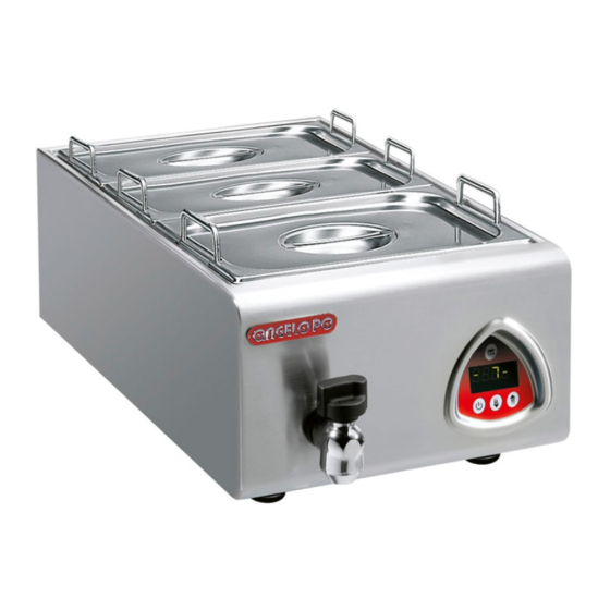
In funzione delle esigenze di utilizzo, l'apparecchia- ta e costruita per la ristorazione professionale e ser- tura è prodotta in più versioni (vedi figura). ve per riscaldare gli alimenti a bagnomaria. 090BM1G 190BM2G IDM-39615800100.tif Organi principali A)Vasca: è realizzata in acciaio inox... - Page 7 DATI TECNICI Vedi tabelle e “Scheda allacciamenti” in fo ndo al manuale. DISPOSITIVI DI SICUREZZA Anche se l'apparecchiatura è completa di tutti i di- spositivi di sicurezza, in fase di installazione e allac- ciamento essi dovr anno, se necessar io, essere integrati con altri in modo da rispettare le leggi vi- genti in materia.
-
Page 8: Sicurezza
ACCESSORI A RICHIESTA A richiesta l’apparecchiatura può essere corredata dei seguenti accessori. A)Bacinelle B)Traversi per bacinelle C)Kit per installazione "su vano" (vedi pag. 16) BGN 1/6 D)Kit per installazione "a ponte" (vedi pag. 16) E)Kit trave di sostegno (vedi pag. 16) BGN 1/1 BGN 2/3 BGN 1/2 BGN 1/3 TRA 11 TRA 12... -
Page 9: Uso E Funzionamento
USO E FUNZIONAMENTO RACCOMANDAZIONI PER L’USO Importante L’incidenza degli infortuni derivante cipali. Attuare solo gli usi previsti dal co- dall’uso di apparecchiature, dipende da struttore manomettere nessun molti fattori che non sempre si riescono a dispositivo per ottenere prestazioni diverse prevenire e controllare. - Page 10 ACCENSIONE E SPEGNIMENTO APPARECCHIATURA Accensione 1 - Aprire il rubinetto alimentazione gas. 2 - Premere e ruotare la manopola (A) in senso an- tiorario (pos. 1) e contemporaneamente mante- nere premuto il pulsante (B) per accendere la spia pilota. 3 - Mantenere premuta la manopola per circa 15 sec per consentire l'intervento della termocop- pia.
- Page 11 Svuotamento 1 - Posizionare un recipiente, di dimensioni ade- guate, in corrispondenza del tubo di scarico (D). 2 - Agire sulla manopola (A) per aprire il rubinetto e svuotare la vasca. 3 - Riportare la manopola nella posizione iniziale a svuotamento concluso.
-
Page 12: Manutenzioni
CONSIGLI PER L’USO Al fine di garantire un corretto uso dell'apparecchia- tura, è bene applicare i seguenti consigli. – Utilizzare esclusivamente gli acces sori indicati dal costruttore. – Prima di riempire la vasca, ver ificare tramite la manopola (A) che il rubinetto di scarico sia chiu- –... - Page 13 PULIZIA APPARECCHIATURA Considerando che l'apparecchiatura è utilizzata per sante idoneo. Si consiglia il lavaggio in lavastovi- la preparazione di prodotti alimentari per l'uomo, è glie. necessario prestare particolare cura a tutto ciò che Cautela - Avvertenza riguarda l'igiene, mantenendo costantemente pulita Non usare prodotti che contengono sostanze l'apparecchiatura e tutto l'ambiente circostante.
-
Page 14: Guasti
CONTROLLO PRESSIONE GAS Per questa operazione procedere nel modo indica- 1 - Chiudere il rubinetto alimentazione gas. 2 - Sfilare la manopola (A). 3 - Svitare le viti (B) e smontare il cruscotto (C). 4 - Svitare la vite (D) della presa di pressione. 5 - Collegare il manometro (E) alla presa di pres- sione (F). - Page 15 Inconvenienti Cause Rimedi La termocoppia non si è riscaldata Insistere più a lungo con l'opera- La spia pilota non rimane accesa a sufficienza zione di accensione Importante Bruciatore sporco, tubi di fumo in- La fiamma è gialla tasati, ricaduta di condensa Contattare il servizio assi- stenza Importante...
-
Page 16: Movimentazione E Installazione
MOVIMENTAZIONE E INSTALLAZIONE RACCOMANDAZIONI PER LA MOVIMENTAZIONE E INSTALLAZIONE Importante Eseguire la movimentazione e l'installazio- ste operazioni dovrà, se necessario, orga- ne nel rispetto delle informazioni fornite dal nizzare "piano sicurezza" costruttore e riportate direttamente sull'im- salvaguardare l'incolumità delle persone ballo, sull'apparecchiatura e nelle istruzioni direttamente coinvolte. - Page 17 MOVIMENTAZIONE E SOLLEVAMENTO L'apparecchiatura può essere movimentata con un dispositivo di sollevament o a forche o a gancio di portata adeguata. Prima di eff ettuare questa operazione, controllare la posizione del baricentro del carico. Importante Nell’inserire il dispositivo di sollevamento, fare attenzione ai tubi di alimentazione e sca- rico.
- Page 18 MONTAGGIO APPARECCHIATURE IN BATTERIA Per montare le apparecchiature in batteria (fianco a fianco) procedere nel modo indicato. 1 - Sfilare le manopole (A). 2 - Svitare le viti (B) e smontare i cruscotti (C). 3 - Smontare, se presente, il sup porto “ferma la- na”.
- Page 19 ALLACCIAMENTO GAS Importante Chi è autorizzato ad effettuare tale opera- zione deve possedere capacità ed espe- rienza acquisita e riconosciuta nel settore specifico, dovrà eseguire l'allacciamento a regola d'arte e tenere conto di tutti i requisi- ti normativi e legislativi. Ad allacciamento completato, prima di rendere operativa l'at- trezzatura, si dovrà...
- Page 20 ALLACCIAMENTO ACQUA Per effettuare l'allacciamento, co llegare il tubo di rete con il tubo di attacco dell'appar ecchiatura, in- terponendo un rubinetto di inter cettazione (A) per interrompere, quando nece ssario, l'alimentazione dell'acqua. A valle di esso installare dei filtri facil- mente raggiungibili.
-
Page 21: Regolazioni
5 - Rimuovere l'adesivo applicato sulla targhetta di identificazione e applicare quello nuovo per evi- denziare il gas in uso. Importante Ad operazione ultimata, accertarsi che non vi siano fuoriuscite di gas o anomalie di funzionamento. IDM-3960200250.tif COLLAUDO APPARECCHIATURA 3 - Verificare la regolare accensione e combustio- Importante ne del bruciatore. - Page 22 REGOLAZIONE MINIMO RUBINETTO VALVOLATO GAS Importante Questa regolazione si effettua solo se il tipo necessario verificare che la pressione del di gas da allacciare è diverso da quello di gas di alimentazione sia conforme al valore collaudo, dopo avere eseguito la trasforma- della pressione nominale relativa allo stes- zione dell'alimentazione (vedi pag.
-
Page 23: Sostituzioni Parti
SOSTITUZIONI PARTI RACCOMANDAZIONI PER LA SOSTITUZIONE PARTI delle persone. Qualora sia necessario sostituire dei Prima di effettuare qualsiasi intervento di sostituzio- ne, attivare tutti i dispositivi di sicurezza previsti e componenti usurati, utilizzare esclusivamente dei valutare se sia necessario informare adeguatamen- ricambi originali. - Page 24 SOSTITUZIONE UGELLO SPIA PILOTA Per questa operazione procedere nel modo indica- 1 - Chiudere il rubinetto alimentazione gas. 2 - Sfilare la manopola (A). 3 - Svitare le viti (B) e smontare il cruscotto (C). 4 - Svitare il raccordo (D). 5 - Estrarre l'ugello (E) e sostituirlo con quello adatto al tipo di gas util izzato (vedi tabella in fondo al manuale).
- Page 25 CONTENTS ref. chapters page 1 GENERAL INFORMATION ..........2 2 TECHNICAL INFORMATION ..........4 3 SAFETY ................6 4 USE AND OPERATION ............. 7 PART 5 SERVICING ..............10 6 FAULT ................12 7 HANDLING AND INSTALLATION ........14 8 ADJUSTMENTS ............... 19 PART 9 REPLACING PARTS ............
-
Page 26: General Information
GENERAL INFORMATION INFORMATION FOR THE READER To find the specific topics of interest to you quickly, 2nd part: contains all the information neces- refer to the index at the start of the manual. sary for spe cial categories of reader, i.e. all This manual is subdivided into two parts. - Page 27 IDENTIFICATION OF CONSTRUCTOR AND APPLIANCE The nameplate shown here is fitted directly to the ) Gas consumption ) Testing gas indicator frame appliance. It contains re ferences and all essential ) Voltage (V) information for operating safety. ) Frequency (Hz) Extra nameplate ) Electricity power consumption (W) ) Country of use...
-
Page 28: Technical Information
The BAIN-MARIE appliance is designed and con- The appliance is produced in several versions to structed for the professional catering sector and is meet varying user requirements (see diagram). intended for heating food by the bain-marie method. 090BM1G 190BM2G IDM-39615800100.tif Main Parts A)Well: in stainless steel... - Page 29 TECHNICAL DATA See tables and "Conne ction chart" at the back of the manual. SAFETY DEVICES Although the appliance is complete with all safety devices, during installation and connection addi- tional devices must be added if necessary to com- ply with the relevant legal requirements. A)Gas supply tap: for turning the connection to the gas supply line on and off.
-
Page 30: Safety
OPTIONAL ACCESSORIES The appliance can be equipped with the following accessories on request. A)Containers B)Bridging bars for containers C)"Over cupboard" installation kit (see page 16). BGN 1/6 D)"Bridge" installation kit (see page 16). E)Supporting beam kit (see page 16). BGN 1/1 BGN 2/3 BGN 1/2 BGN 1/3 TRA 11 TRA 12 TRA 16... -
Page 31: Use And Operation
USE AND OPERATION RECOMMENDATIONS FOR USE Important The rate of accidents deriving from the use and the main functions. Use only as intend- of appliances depends on many factors ed by the constructor and never tamper which cannot always be foreseen and con- with any device to obtain performance lev- trolled. - Page 32 SWITCHING THE APPLIANCE ON AND OFF Lighting 1 - Turn on the gas supply tap. 2 - Press the knob (A) and turn it anti-clockwise (pos. 1), while keeping button (B) pressed, to light the pilot light. 3 - Keep the knob pressed for about 15 sec. to prime the thermocouple.
- Page 33 Emptying 1 - Place a container of suitab le size un derneath the drain pipe (D). 2 - Use the knob (A) to turn on the tap and empty the well. 3 - Return the knob to its original position once the well has been drained.
-
Page 34: Servicing
USEFUL ADVICE FOR USE To ensure correct use of the appliance, the follow- ing rules should be adopted. – Use only the accessories r ecommended by the constructor. – Before filling the well, use the knob (A) to check that the drain tap is turned off. –... - Page 35 CLEANING INSTRUCTIONS Since the appliance is used for preparing foods for grease-remover product. If possible, wash in the human consumption, special care must be paid to dishwasher. everything relating to hygiene, and the appliance Caution - warning and the entire surrounding environment must con- Never use products containing substances stantly be kept clean.
-
Page 36: Fault
CHECKING GAS PRESSURE To carry out this operation, proceed as follows. 1 - Turn off the gas supply tap. 2 - Pull off the knob (A). 3 - Undo the scr ews (B) and remo ve the control panel (C). 4 - Undo the screw (D) of the pressure connection. - Page 37 Faults Causes Remedies The thermocouple has not Make more attempts to light the The pilot light goes out warmed up enough flame Important Burner dirty, heat exchange pipes The flame is yellow clogged, condensation drips Contact the after-sales service Important Burner control knob is stiff Gas control valve malfunction Contact the after-sales...
-
Page 38: Handling And Installation
HANDLING AND INSTALLATION RECOMMENDATIONS FOR HANDLING AND INSTALLATION Important When handling and installing the appliance use. If necessary, the person authorised to comply with the information provided by carry out these operations must organise a the constructor directly on the packaging, "safety plan"... - Page 39 HANDLING AND LIFTING The appliance can be handled using fork-lift or hook equipment of suitable load- carrying capacity. Be- fore lifting, check the position of the load's centre of gravity. Important When engaging with the lifting equipment, watch out for the gas supply pipe. IDM-39615801200.tif INSTALLATION OF THE APPLIANCE All installation stages must be considered right from...
- Page 40 ASSEMBLY APPLIANCES IN BANKS To assemble appliances in banks (side by side) proceed as described below. 1 - Pull off the knob (A). 2 - Undo the scr ews (C) and remo ve the control panels (B). 3 - Remove the "insulation retainer" , if fitted. 4 - Apply masking tape to the edges to be placed side by side.
- Page 41 GAS CONNECTION Important Those authorised to carry out this opera- tion must have experience acquired and certified in the specific sector, must make the connection to the proper standards, and must comply with all the relevant regu- lations and legislation. Once the connec- tion has been made, before the appliance is put into operation a general check must be made to ensure there are no gas leaks.
- Page 42 WATER CONNECTION To make the connection, connect the mains line to the appliance's connection pipe, fitting a shut-off tap (A), to allow the water supply to be cut off when necessary. Easily accessible filters must be fitted downstream of the tap. Caution - warning The appliance must be supplied with drinking water having the characteristics shown in the...
-
Page 43: Adjustments
5 - Remove the sticker from the nameplate and ap- ply the new one to identify the gas being used. Important On completion of the operation, make sure that there are no gas leaks or malfunctions. IDM-3960200250.tif TESTING OF THE APPLIANCE 3 - Check that the burner is switching on correctly Important and its combustion. - Page 44 ADJUSTING GAS CONTROL VALVE MINIMUM SETTING Important This adjustment is only required if the type fore making this adjustment, check that the of gas to be connected is different from that gas supply pressure is the same as the rat- used for testing after the conversion proce- ed pressure for the type of gas in use (see dure has been carried out (see page 18).
-
Page 45: Replacing Parts
REPLACING PARTS RECOMMENDATIONS FOR REPLACING PARTS Before carrying out any replacement procedure, ac- worn parts have to be replaced, use original spare tivate all the safety devices p rovided and decide parts only. The manufacturer declines all responsi- whether staff at work and those in the vicinity bly for injury or damage to components du e to the should be informed. - Page 46 REPLACEMENT OF THE PILOT LIGHT INJECTOR To carry out this operation, proceed as follows. 1 - Turn off the gas supply tap. 2 - Pull off the knob (A). 3 - Undo the scr ews (B) and remo ve the control panel (C).
- Page 47 INHALTSVERZEICHNIS Ref. Kapitel Seite 1 ALLGEMEINES ..............2 2 TECHNISCHE INFORMATIONEN ........4 3 SICHERHEIT ..............6 4 GEBRAUCH UND BETRIEB ..........7 1. TEIL 5 WARTUNG ............... 10 6 DEFEKTE ................. 12 7 HANDHABUNG UND INSTALLATION ......14 8 EINSTELLUNGEN ............19 2.
-
Page 48: Allgemeines
ALLGEMEINES INFORMATIONEN FÜR DEN LESER Konsultieren Sie das Sachregister, das am Anfang 2. Teil: Diese Informationen wenden sich an des Handbuchs zu finden ist, um leichter unter be- eine bestimmte Zielgruppe. Sie sind für erfahre- stimmten Themen von beson derem Interesse ne Bediener bestimmt, die fü... - Page 49 TYPENSCHILD FÜR HERSTELLER UND GERÄT Das abgebildete Typenschild wird direkt auf dem ) Gasverbrauch ) Testgasanzeige Gerät aufgebracht. Es enthält sämtliche Angaben ) Spannung (V) und Hinweise, die für den sicheren Betrieb unerläs- ) Frequenz (Hz) slich sind. ) Leistungsaufnahme (W) Ergänzungsschild ) Abnahmespannungsanzeige ) Benutzerland...
-
Page 50: Technische Informationen
Das Gerät BAINMARIE wurde für den Gebrauch in Das Gerät wird bedarfsabhängig in verschiedenen Restaurantbetrieben projektiert und konstruiert und Versionen hergestellt (siehe Abbildung). dient zum Erwärmen der Lebensmittel im Wasser- bad. 090BM1G 190BM2G IDM-39615800100.tif Hauptorgane A)Becken: aus Edelstahl B)Bedienknebel Brenner: um die Gaszufuh r zu den Brennern einzustellen C)Schalter für Wasserablauf: zum Ablassen des... - Page 51 TECHNISCHE DATEN Siehe Tabellen und „Anschlussschema" am Ende des Handbuchs. SICHERHEITSVORRICHTUNGEN Das Gerät wird zwar mit sämtlichen planmäß igen Sicherheitsvorrichtungen geliefert, es kann je doch notwendig sein, während Installation und An- schluss ggf. weitere ergänzende Maßnahmen zu ergreifen, um d en Anforderungen der einschlägi- gen geltenden Gesetze zu entsprechen.
-
Page 52: Sicherheit
OPTIONALES ZUBEHÖR Auf Wunsch kann das Gerät mit folgenden Zube- hörteilen ausgestattet werden. A)Behälter B)Träger für Behälter C)Einbausatz für die Montage auf Unterschrank (siehe BGN 1/6 Seite 16). D)Einbausatz für Brückenmontage (siehe Seite 16). E)Einbausatz für Träger (siehe Seite 16). BGN 1/1 BGN 2/3 BGN 1/2 BGN 1/3 TRA 11 TRA 12... -
Page 53: Gebrauch Und Betrieb
GEBRAUCH UND BETRIEB EMPFEHLUNGEN FÜR DEN GEBRAUCH Wichtig Das Auftreten von Unfällen bei der Verwen- ken Sie sich auf die vom Hersteller vorgese- dung von Geräten hängt von vielen Fakto- henen Verwendungszwecke, ohne ren ab, die nicht immer zu vermeiden und Änderungen an den Vorrichtungen vorzu- nehmen, um nicht vorgesehene Leistungen zu steuern sind. - Page 54 EIN- UND AUSSCHALTEN DES GERÄTS Zündung 1 - Öffnen Sie den Gashahn. 2 - Schalter (A) niederdrücken und entgegen dem Uhrzeigersinn drehen (Pos. 1); gleichzeitig die Taste (B) zum Zünden des Zündflammenbren- ners gedrückt halten. 3 - Halten Sie den Bedienknebel etwa 15 Sekun- den lang g edrückt, damit d as Thermoelement in Aktion treten kann.
- Page 55 Entleeren 1 - Ein passend großes Gefäß unter das Abfluss- rohr (D) stellen. 2 - Mit dem Schalter (A) den Hahn öffnen und das Becken entleeren. 3 - Nach dem Entleeren den Schalter wieder in die ursprüngliche Schaltstellung drehen. IDM-39615800800.tif RÜCKSETZEN DES GERÄTS Wenn der Sicherheitsthermostat anspricht, muss das Gerät in der angegebenen Weise wieder in den...
-
Page 56: Wartung
TIPPS FÜR DEN GEBRAUCH Um eine korrekte Anwendung des Gerätes zu ge- währleisten, sollten folgende Ratschläge befolgt werden: – Verwenden Sie ausschließlich das vom Herstel- ler angegebene Zubehör. – Vor dem Füllen des Beckens anhand des Schal- ters (A) kontrollieren, ob der Ablasshahn ge- schlossen ist. - Page 57 REINIGUNG DES GERÄTS Da das Gerät zur Zubereitung von Speisen für den Vorsicht – Achtung Menschen eingesetzt wird, ist besondere Sorgfalt Verwenden Sie keine Produkte, die Stoffe ent- auf die Hyg iene geboten. Das Ger ät und dessen halten, welche für die menschliche Gesund- näheres Umfeld müssen konstant sauber gehalten heit schädlich...
-
Page 58: Defekte
KONTROLLE DES GASDRUCKS Für diesen Vorgang in der ang egebenen Weise verfahren. 1 - Schließen Sie den Gaszufuhrhahn 2 - Den Schalter (A) abziehen. 3 - Drehen Sie die Sch rauben (B) heraus und montieren Sie die Blende (C) ab. 4 - Drehen Sie die Schrauben (D) aus dem Druck- prüfpunkt. - Page 59 Probleme Ursachen Lösungen Der Zündflammenbrenner bleibt Das Thermoelement ist nicht ausrei- Versuchen Sie erneut und länger, nicht eingeschaltet chend aufgeheizt den Zündungsvorgang zu starten Der Brenner ist verschmutzt, das Die Flamme ist gelb Gasabzugsrohr ist verstopft, Kon- Wichtig denswassertropfen Kontaktieren Sie den Kundendienst Schwierigkeiten beim Drehen des Fehlfunktion des vollgesicherten Wichtig...
-
Page 60: Handhabung Und Installation
HANDHABUNG UND INSTALLATION EMPFEHLUNGEN FÜR DIE INSTALLATION UND HANDHABUNG Wichtig Beachten Sie die Hinweise des Herstellers, nen autorisierte Person wird bei Bedarf die direkt auf der Verpackung, auf dem Ge- einen „Sicherheitsplan" aufstellen müssen, rät selbst oder in der Gebrauchsanweisung um die Unversehrtheit der direkt an dem zu finden sind, wenn Sie das Gerät handha- Vorgang beteiligten Personen zu gewähr-... - Page 61 HANDHABUNG UND HUB Das Gerät kann mit einem Hubmittel bewegt wer- den, das mit Gabeln oder H aken ausgestattet ist und die geeignete Traglast besitzt. Vor diesem Vor- gang ist der Schwerpunkt der Last zu überprüfen. Wichtig Achten Sie beim Einsatz des Hubmittels auf das Gaszufuhrrohr.
- Page 62 MONTAGE BEI REIHENAUFSTELLUNG Verfahren Sie folgendermaßen, um Geräte (neben- einander) in einer Reihe aufzustellen. 1 - Den Schalter (A) abziehen. 2 - Die Schrauben (C) ausschrauben und die Blen- den (B) ausbauen. 3 - Falls vorhanden, die Halterung der Dämmwolle ausbauen.
- Page 63 GASANSCHLUSS Wichtig Diese Arbeit darf nur von zugelassenen und erfahrenen Fachleuten ausgeführt wer- den. Der Anschluss muss fachgerecht und vorschriftsmäßig ausgeführt werden und allen einschlägigen gesetzlichen Bestim- mungen entsprechen. Nach Ausführung des Anschlusses muss vor der Inbetrieb- nahme des Geräts durch eine allgemeine Kontrolle sichergestellt werden, dass nir- gends Gas austritt.
- Page 64 WASSERANSCHLUSS Schließen Sie den Zufuhr schlauch der Wasserlei- tung an das Anschlussrohr des Gerätes an. Bringen Sie hierbei einen Absperrhahn (A) an, um die Was- serzufuhr bei Bedarf absperren zu kön nen. Hinter diesen Absperrhahn müssen leicht zugängliche Fil- ter eingebaut werden. Vorsicht –...
-
Page 65: Einstellungen
5 - Entfernen Sie den alten Aufkleber vom Typen- schild und ersetzen Sie ihn durch den neuen Aufkleber, um den verwendeten Gastyp anzu- zeigen. Wichtig Stellen Sie nach Abschluss dieses Vor- gangs sicher, dass kein Gas austritt und keine Funktionsstörungen auftreten. IDM-3960200250.tif TESTLAUF ZUR ABNAHME DES GERÄTS 3 - Sicherstellen, dass Zündung und Verbrennung... - Page 66 EINSTELLUNG DER KLEINSTELLUNG BEIM VOLLGESICHERTEN GASVENTIL Wichtig Diese Einstellung muss nur ausgeführt man sicherstellen, dass der Druck im Gas- werden, wenn die anzuschließende Gasart netz dem für die jeweilige Gasart vorge- von der Prüfgasart verschieden ist, d.h. schriebenen Nenndruck entspricht (siehe also im Anschluss an eine Gasumstellung die Tabelle am Ende des Handbuchs).
-
Page 67: Austausch Von Bauteile
AUSTAUSCH VON BAUTEILE HINWEISE ZUM AUSTAUSCH VON TEILEN Vor Ausführung eines Austauschs alle vorgesehe- der Gesundheit von Personen bee inträchtigen nen Sicherheitseinrichtungen einschalten und in könnten. Zum Er setzen von ve rschlissenen Kom- Erwägung ziehen, ob die angemessene Unterrich- ponenten ausschließlich Originalersatzteile ver- tung des ausführende n Personals und der in der wenden. - Page 68 AUSWECHSELN DES ZÜNDFLAMMENBRENNERS Für diesen Vorgang in der ang egebenen Weise verfahren. 1 - Schließen Sie den Gaszufuhrhahn 2 - Den Schalter (A) abziehen. 3 - Drehen Sie die Sch rauben (B) heraus und montieren Sie die Blende (C) ab. 4 - Drehen Sie das Verbindungsstück (D) heraus.
- Page 69 INDEX réf. chapitres page 1 INFORMATIONS GENERALES ......... 2 2 INFORMATIONS TECHNIQUES ........4 3 SÉCURITÉ ................. 6 4 UTILISATION ET FONCTIONNEMENT ......7 PARTIE 5 ENTRETIEN ..............10 6 PANNES ................12 7 MANUTENTION ET INSTALLATION ....... 14 8 RÉGLAGES ..............19 PARTIE 9 REMPLACEMENT DE PIÈCES ........
- Page 70 INFORMATIONS GENERALES INFORMATIONS POUR LE LECTEUR Pour retrouver facilement les sujets qui vous inté- 2e partie: elle contient toutes les info rma- ressent, consulter l’index analytique au début du tions nécessaires aux destinataires homogè- manuel. nes, c’est-à-dire tous les opérateurs experts Ce manuel est divisé...
- Page 71 IDENTIFICATION DU FABRICANT ET DE L’APPAREIL La plaque d’identification représentée, est appli- ) Puissance déclarée (kW) ) Consommation de gaz quée directement sur l'appareil. Elle reporte les ré- ) Indicateur du gaz d’essai férences et les indica tions indispensables à la ) Tension (V) sécurité.
- Page 72 En fonction des e xigences d'utilisation, l'appareil pour la restauration professionnelle et sert pour ré- est réalisé en plusieurs versions (voir figure). chauffer les aliments au bain marie. 090BM1G 190BM2G IDM-39615800100.tif Organes principaux A)Cuve: en acier inox B)Manette de commande du brûleur: pour régler l’alimentation du gaz au brûleur...
- Page 73 DONNÉES TECHNIQUES Voir tableaux et « Fiche des raccordements » à la fin du manuel. DISPOSITIFS DE SÉCURITÉ Même si l’appareil est complet de tous les disposi- tifs de sécurité, lors de l’installation et du raccorde- ment, ils devront, si nécessaire, être intégrés avec d’autres pour respecter les lois en vigueur.
- Page 74 ACCESSOIRES SUR DEMANDE Sur demande l'appareil peut être équipé des acces- soires suivants. A)Bacs B)Traverses pour bacs C)Kit pour installation « sur soubassement » (voir BGN 1/6 page 16). D)Kit pour installation « en pont » (voir page 16). E)Kit traverse de soutien (voir page 16). BGN 1/1 BGN 2/3 BGN 1/2 BGN 1/3 TRA 11 TRA 12...
- Page 75 UTILISATION ET FONCTIONNEMENT RECOMMANDATIONS POUR L'UTILISATION Important L’incidence des accidents dérivant de l’uti- les. Utiliser seulement comme prévu par le lisation d’appareils dépend de beaucoup de fabricant et ne modifier aucun dispositif facteurs que l’on ne peut pas toujours pré- pour obtenir des performances différentes venir et contrôler.
- Page 76 ALLUMAGE ET EXTINCTION DE L’APPAREIL Allumage 1 - Ouvrir le robinet d’alimentation du gaz. 2 - Pousser et tourner la manette (A) en sens anti- horaire (pos. 1) et simultanément tenir pressé le bouton (B) pour allumer la veilleuse pilote. 3 - Continuer à...
- Page 77 Vidange 1 - Placer un récipient, de dimensions appro- priées, sous le tuyau de vidange (D). 2 - Agir sur la manette (A) pour ouvrir le robinet et vider la cuve. 3 - Reporter la manette à sa position initiale lors- que la vidange est terminée.
- Page 78 CONSEILS D’UTILISATION Afin de garantir une utilisation correcte de l’appa- reil, suivre ces conseils. – Utiliser exclusivement les accessoires indiqués par le fabricant. – Avant de remplir la cuve, vérifier, par la manette (A), si le robinet de vidange est fermé. –...
- Page 79 NETTOYAGE DE L’APPAREIL Etant donné que l’appareil est utilisé pour la prépa- avec un dégraissant appr oprié. Le la vage en ration de produits alimentaires pour l’homme, il faut lave-vaisselle est conseillé. faire attention à tout ce qui concerne l’hygiène; l’ap- Attention pareil et tout ce qui l’entoure do ivent toujours être Ne pas utiliser de produits qui contiennent...
- Page 80 CONTRÔLE DE LA PRESSION DU GAZ Pour cette opération, procéder comme suit. 1 - Fermer le robinet d’alimentation du gaz. 2 - Enlever la manette (A). 3 - Dévisser les vis (B) et démonter le tableau de commandes (C). 4 - Dévisser la vis (D) de la prise de pression. 5 - Raccorder le manomètre (E) à...
- Page 81 Inconvénients Causes Solutions La veilleuse pilote ne reste pas al- Le thermocouple n’est pas suffi- Insister avec l’allumage lumée samment chaud Brûleur sale, tuyaux de fumée Important La flamme est jaune obstrués, rechute de vapeur d’eau Contacter le service condensée assistance Important Difficulté...
- Page 82 MANUTENTION ET INSTALLATION RECOMMANDATIONS POUR LA MANUTENTION ET L’INSTALLATION Important Effectuer la manutention et l’installation en effectuer ces opérations devra, si nécessai- respectant les informations fournies par le re, organiser un « plan de sécurité » pour fabricant, reportées directement sur l’em- sauvegarder la sécurité...
- Page 83 MANUTENTION ET LEVAGE L'appareil peut être manutent ionné avec un dispo- sitif de levage à fourches ou à crochet d’une capa- cité de charge appropriée. Avant d’effectuer cette opération, contrôler la position du centre de gravité de la charge. Important En introduisant le dispositif de levage, faire attention au tuyau d’alimentation du gaz.
- Page 84 MONTAGE DES APPAREILS EN BATTERIE Pour monter les appare ils en batte rie (les uns à côté des autres), procéder comme suit. 1 - Enlever la manette (A). 2 - Dévisser les vis (C) et démonter les tableaux de commandes (B). 3 - Démonter, s’il est présent, le support de bloca- ge de la laine.
- Page 85 RACCORDEMENT DU GAZ Important La personne autorisée à effectuer cette opération devra avoir les capacités et l’ex- périence acquise et reconnue dans le sec- teur spécifique; elle devra effectuer le raccordement dans les règles de l’art et te- nir compte de toutes les exigences impo- sées par les normes et les lois.
- Page 86 RACCORDEMENT DE L'EAU Pour effectuer le raccordement, raccorder le tuyau de réseau et le tuyau de raccord de l’appareil, en in- terposant un robinet d’arrêt (A), pour interrompre, si nécessaire, l’alimentation de l’eau. En aval de celui- ci, installer des filtres facilement accessibles. Attention L’appareil doit être alimenté...
- Page 87 5 - Enlever l’adhésif collé sur la plaque d’identifica- tion et appliquer le nouveau pour mettre en évi- dence le gaz utilisé. Important Lorsque l’opération est terminée, s’assurer qu’il n’y ait pas de fuites de gaz ou d’ano- malies de fonctionnement. IDM-3960200250.tif ESSAI DE L’APPAREIL 3 - Vérifier l'allumage régulier et la combustion du...
- Page 88 RÉGLAGE DU MINIMUM DU ROBINET GAZ DE SÉCURITÉ Important Ce réglage n'est effectué que si le type de gaz réglage, vérifier que la pression du gaz d'ali- à raccorder est différent de celui d'essai et mentation soit conforme à la valeur de la pres- après avoir effectué...
- Page 89 REMPLACEMENT DE PIÈCES RECOMMANDATIONS POUR LE REMPLACEMENT DES PIÈCES Avant d'effectuer tout remplacement, activer les posants usés, utiliser exclusivement des pièces de dispositifs de sécurité prévus et évaluer s'il faut in- rechange d'origine. Le fabricant décline toute res- former les opérateurs travaillant sur l'appareil et ponsabilité...
- Page 90 REMPLACEMENT DE LA BUSE DE LA VEILLEUSE PILOTE Pour cette opération, procéder comme suit. 1 - Fermer le robinet d’alimentation du gaz. 2 - Enlever la manette (A). 3 - Dévisser les vis (B) et démonter le tableau de commandes (C). 4 - Dévisser le raccord (D).
- Page 91 ÍNDICE ref. capítulos pág 1 INFORMACIONES DE CARÁCTER GENERAL ....2 2 INFORMACIONES DE CARÁCTER TÉCNICO ....4 3 SEGURIDAD ..............6 4 USO Y FUNCIONAMIENTO ..........7 PARTE 5 MANTENIMIENTO ............10 6 AVERÍAS ................12 7 DESPLAZAMIENTO E INSTALACIÓN ......14 8 REGULACIONES .............
-
Page 92: Informaciones De Carácter General
INFORMACIONES DE CARÁCTER GENERAL INFORMACIONES PREVIAS Para ubicar fácilmente los temas específicos de in- 2a parte: contiene todas las info rmaciones ne- terés, consúltese el índice analítico que se encuen- cesarias para destinat arios homogéneos, esto tra al inicio del manual. es, todos los operadores expertos y autorizados Este manual comprende dos partes. - Page 93 IDENTIFICACIÓN FABRICANTE Y EQUIPO La placa de identificación fijada directamente en el ) Consumo de gas ) Indicador gas prueba de funcionamiento equipo reproduce todas las referencias e indicacio- ) Tensión (V) nes indispensables para la seguridad de servicio. ) Frecuencia (Hz) Placa complementaria ) Potencia eléctrica absorbida (W) ) País de uso...
-
Page 94: Informaciones De Carácter Técnico
El aparato es producido en varias versiones en fun- cado para el sector de la restauración profesional y ción de los requerimientos específicos de uso (véa- se utiliza para calentar los alimentos en bañomaría. se figura). 090BM1G 190BM2G IDM-39615800100.tif Órganos principales A)Cuba: fabricada en acero inox B)Mando del quemador: para regular la alimentación... - Page 95 DATOS TÉCNICOS Véase tablas y "F icha de enlaces" al final del ma- nual. DISPOSITIVOS DE SEGURIDAD Aunque el equipo cuente con todos los dispositivos de seguridad, en los casos en que así lo determi- nen las leyes vigentes en materia, se deberá com- plementar con otr os dispositivos en las fases de instalación y enlace.
-
Page 96: Seguridad
ACCESORIOS BAJO PEDIDO Bajo pedido, el equipo puede ser suministrado con los accesorios que a continuación se indican. A)Cubetas B)Distanciadores para cubetas C)Kit para la instalación "en mueble" (véase pág. 16). BGN 1/6 D)Kit para la instalación "de puente" (véase pág. 16). E)Kit barra de soporte (véase pág. -
Page 97: Uso Y Funcionamiento
USO Y FUNCIONAMIENTO RECOMENDACIONES DE USO Importante El porcentaje de accidentes derivados del Se deben ejecutar sólo operaciones pro- uso de equipos depende de muchos facto- pias de los usos previstos por el fabricante. res que no siempre se logran prevenir y No alterar los equipos con el fin de obtener controlar. - Page 98 ENCENDIDO Y APAGADO DEL APARATO Encendido 1 - Abrir el grifo de alimentación del gas. 2 - Presionar y hacer girar el mando (A) en sentido antihorario (pos. 1) manteniendo simultánea- mente presionado el botón (B) para encender el piloto. 3 - Mantener presionado el mando durante aprox.
- Page 99 Vaciado 1 - Coloque un recipiente de dimensiones adecua- das en cor respondencia del tubo de desagüe (D). 2 - Operar con el mando (A) para abrir el grifo y va- ciar la cuba. 3 - Una vez concluido el vaciado, devolver el man- do a la posición inicial.
-
Page 100: Mantenimiento
CONSEJOS PARA EL USO A fin de garantizar un uso correcto del equipo, apli- car las siguientes recomendaciones. – Utilizar exclusivamente los accesorios indicados por el fabricante. – Antes de llenar la cuba verificar mediante el man- do (A) que el grifo de descarga esté cerrado. –... - Page 101 LIMPIEZA APARATO Atendida la circunstancia de que el equipo es utili- – Limpiar los accesorios después del uso utilizan- zado para la preparación de productos alimenticios do un dese ngrasante adecuado. Se aconseja para el consumo humano, es necesario prestar es- efectuar el lavado en lavavajillas.
-
Page 102: Averías
CONTROL DE LA PRESIÓN DEL GAS Para efectuar esta operación, aplicar las siguientes instrucciones. 1 - Cerrar el grifo de alimentación del gas. 2 - Retirar el mando (A). 3 - Desenroscar los tornillos (B) y desmontar el ta- blero de instrumentos (C). 4 - Desenroscar el tornillo (D) de la toma de pre- sión. - Page 103 Inconvenientes Causas Remedios El testigo piloto no se mantiene El termopar no se ha calentado Insistir con la operación encendido suficientemente de encendido Quemador sucio, tubos de humo La llama presenta color amarillo obstruidos, caída de condensa- Importante ción Contactar el servicio de asistencia Dificultad para girar el mando de Malfuncionamiento de la llave con Importante...
-
Page 104: Desplazamiento E Instalación
DESPLAZAMIENTO E INSTALACIÓN RECOMENDACIONES PARA EL DESPLAZAMIENTO Y LA INSTALACIÓN Importante Efectuar el desplazamiento e instalación rizada para efectuar estas operaciones de- respetando las indicaciones proporciona- berá, si fuera necesario, organizar un "plan das por el fabricante, reproducidas directa- de seguridad", a fin de salvaguardar la in- mente sobre el embalaje, en el equipo y en columidad de las personas directamente las instrucciones de uso. - Page 105 DESPLAZAMIENTO Y ELEVACIÓN El equipo puede ser desplazado con un equipo de elevación de horquillas o de gancho, de capacidad adecuada. Para ejecuta r esta oper ación se debe controlar atentamente el centro de gravedad de la carga. Importante Proceder con cautela al introducir el equipo de elevación a fin de no dañar el tubo de ali- mentación del gas.
- Page 106 MONTAJE DE EQUIPOS EN BATERÍA Para montar los equipos en batería (uno al lado del otro) aplicar las siguientes instrucciones. 1 - Retirar el mando (A). 2 - Desenroscar los tornillos (C) y desmontar los paneles de mando (B). 3 - En caso de estar presente, desmontar el sopor- te "fijador lana".
- Page 107 ENLACE GAS Importante El personal autorizado para ejecutar esta operación debe poseer capacidad y haber adquirido experiencia efectiva en el sector específico; la conexión deberá ejecutarse respetando rigurosamente todos los requi- sitos establecidos por las normativas vi- gentes. Una vez efectuada la conexión, antes de poner en funcionamiento el apara- to se deberá...
- Page 108 ENLACE AGUA Para efectuar el enlace, conectar el tubo de red con el tubo de conexión del equipo, instalando un grifo de interceptación (A) a fin de poder inte rrumpir, cuando sea necesario, la alimentación del agua. En posición sucesiva al grifo se deben instalar filtros de fácil acceso.
-
Page 109: Regulaciones
5 - Retirar el adhesivo pr esente en la placa de identificación y fijar el nuevo adhesivo relativo al tipo de gas a utilizar. Importante Una vez concluida la operación, controlar que no haya fugas de gas o anomalías de funcionamiento. - Page 110 REGULACIÓN MÍNIMO GRIFO CON VÁLVULA DE SEGURIDAD GAS Importante Esta regulación deberá efectuarse sólo si el regulación se deberá verificar que la pre- tipo de gas a conectar es diferente de aquél sión del gas de alimentación corresponda de prueba en fábrica y después de haber al valor de presión nominal relativo a ese efectuado la transformación de la alimenta- tipo de gas (véase tabla en la parte conclu-...
-
Page 111: Sostitución De Piezas
SOSTITUCIÓN DE PIEZAS RECOMENDACIONES PARA EFECTUAR LA SUSTITUCIÓN DE LAS PIEZAS Antes de cambiar eventuales piezas del aparato, que sea necesario cambiar algún componente de- active todos los dispositivos de seguridad previstos teriorado, sírvase exclusivamente de recambios e informe oportunamente tanto el personal encar- originales. - Page 112 SUSTITUCIÓN INYECTOR TESTIGO PILOTO Para efectuar esta operación, aplicar las siguientes instrucciones. 1 - Cerrar el grifo de alimentación del gas. 2 - Retirar el mando (A). 3 - Desenroscar los tornillos (B) y desmontar el ta- blero de instrumentos (C). 4 - Desenroscar el racor (D).
- Page 113 (Min. 4 kW) G25.1 2 W / 230V1~N 090BM1G N. 1 0,53 m /h 0,62 m /h 0,39 kg/h 0,39 kg/h 50/60 Hz SCHEDA ALLACCIAMENTI (090BM1G) - CONNECTION CARD (090BM1G) - ANSCHLUSSSCHEMA (090BM1G) FICHE RACCORDEMENTS (090BM1G) - FICHA DE ENLACES (090BM1G) IDM-39615802000.tif...
- Page 114 Bruciatore Consumo gas Allacciamento elettrico Burner - Brenner Gas consumption - Gasverbrauch Modello Electrical connection Bruleur - Quemadore Consommation de gaz - Consumo de gas Model - Modelle Stromanschluss 5 kW 8 kW Modèle - Modelo Branchement électrique Conexión eléctrica (Min.
- Page 115 SCHEMA ELETTRICO - ELECTRIC DIAGRAM - SCHALTBILD SCHÉMA ÈLECTRIQUE - ESQUEMA ELÉCTRICO IDM-39615802200.tif 1) Morsettiera - Terminal board - Klemmenbrett - Plaque à bornes - Regleta de conexión 2) Pulsante acqua - Water button - Taste Wasser - Bouton de l'eau - Botón agua - Electroválvula agua 3) Pulsante accensione - Ignition button - Taste Zündung - Bouton d'allumage - Botón de encendido...
- Page 116 Tabella iniettori bruciatore 090BM1G - Burner injector table 090BM1G - Tabelle: Düsen Brenner 090BM1G - Tableau des injecteurs des brûleurs 090BM1G - Tabla inyectores quemador 090BM1G pen mbar Qn max p (3) mbar ø (4) ø (5) ø (6) Qn min p (7) mbar ø...
- Page 117 Tabella iniettori bruciatore 090BM1G - Burner injector table 090BM1G - Tabelle: Düsen Brenner 090BM1G - Tableau des injecteurs des brûleurs 090BM1G - Tabla inyectores quemador 090BM1G pen mbar Qn max p (3) mbar ø (4) ø (5) ø (6) Qn min p (7) mbar ø...
- Page 118 Tabella iniettori bruciatore 190BM2G - Burner injector table 190BM2G - Tabelle: Düsen Brenner 190BM2G - Tableau des injecteurs des brûleurs 190BM2G - Tabla inyectores quemador 190BM2G pen mbar Qn max p (3) mbar ø (4) ø (5) ø (6) Qn min p (7) mbar ø...
- Page 119 Tabella iniettori bruciatore 190BM2G - Burner injector table 190BM2G - Tabelle: Düsen Brenner 190BM2G - Tableau des injecteurs des brûleurs 190BM2G - Tabla inyectores quemador 190BM2G pen mbar Qn max p (3) mbar ø (4) ø (5) ø (6) Qn min p (7) mbar ø...
- Page 120 Tabella caratteristiche gas - Table of gas characteristics - Tabelle der Gas-Eigenschaften Tableau des caractéristiques du gaz - Tabla características gas Potere calorifero inferiore (Hi) Famiglia Tipo di gas Indice Wobbe (MJ/m Net calorific value (Hi) Group Gas type Wobbe index (MJ/m Unterer Heizwert (Hi) Familie Gastypen...
Need help?
Do you have a question about the 090BM1G and is the answer not in the manual?
Questions and answers