
Related Manuals for Angelo Po 091CP1G


Summary of Contents for Angelo Po 091CP1G
- Page 1 091CP1G PASTA COOKER 191CP2G USE AND INSTALLATION MANUAL English Ed. 0 04/2009 3125771...
-
Page 3: Table Of Contents
21 Abnormal operation, 10 Adjusting burner primary Gas pressure, checking, 11 Recommendations for servicing, 10 air (091CP1G - 191CP2G), 21 Gas supply, conversion, 18 Recommendations for use, 7 Adjusting gas control valve minimum Gas tap, greasing, 21 Replacement of parts,... -
Page 4: General Information
GENERAL INFORMATION INFORMATION FOR THE READER To find the specific topics of interest to you quickly, part: contains all the information neces- refer to the index at the start of the manual. sary for special categories of reader, i.e. all This manual is subdivided into two parts. -
Page 5: Technical Information
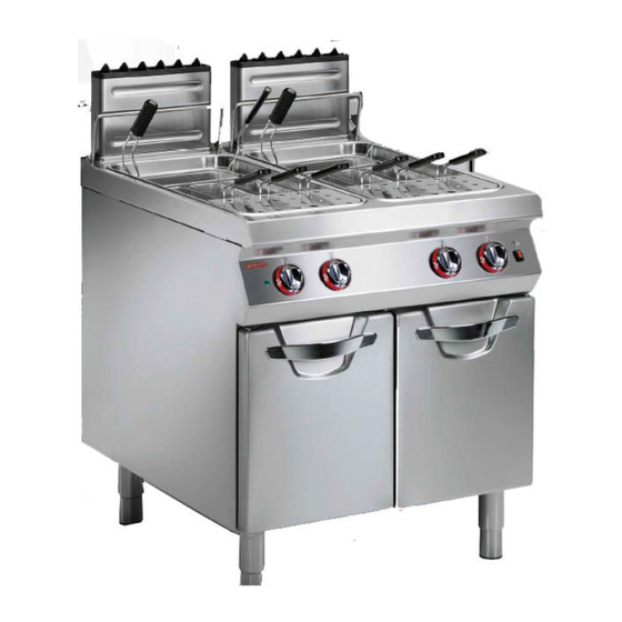
The pasta cooker (referred to below as the appli- The appliance is produced in several versions to ance) is designed and constructed to cook pasta for meet varying user requirements (see diagram). human consumption in water, in the professional catering sector. 091CP1G 191CP2G IDM-39614900201.tif - 3 - English... - Page 6 Main Parts A)Cooking well: in stainless steel. B)Fume exhaust vent (Type (A): for removal of the fumes generated by the burner C)Fume exhaust vent (type B11): removes the fumes and conveys them to a flue fitted with an extraction system serving the gas system. D)Fume exhaust vent (type B11): removes the fumes and conveys them to a flue with natural draft and with draught damper device.
- Page 7 SAFETY AND INFORMATION SIGNS The illustration shows the position of the signs pro- vided. A)Nameplate with manufacturer and appliance data. B)Burn hazard: watch out for hot surfaces. C)General hazard: when washing the appliance do not point pressurised water jets at internal parts. D)General hazard: read the manual carefully be- fore carrying out any procedure.
-
Page 8: Safety
SAFETY SAFETY REGULATIONS During design and construction, the constructor has To maintain hygiene and protect the food proc- paid special attention to factors which may cause essed from all forms of contamination, all elements risks to the health and safety of the people interact- in direct or indirect contact with foodstuffs and all ing with the appliance. -
Page 9: Use And Operation
ENVIRONMENTAL IMPACT SAFETY REGULATIONS Every organisation is obliged to apply procedures ised to interact with the appliance during its to identify and monitor the effects of its operations expected lifetime, in order to prevent environmental (products, services, etc.) on the environment. impact. - Page 10 DESCRIPTION OF CONTROLS The appliance is fitted with the controls for use of its B)Water control knob: for filling the well in the various main functions. ways available. A)Burner control knob: for lighting, turning off and C)Ignition button: lights the pilot light. regulating the relative burner and pilot light D)Mains light: indicates that the appliance is receiving electrical power.
- Page 11 FILLING AND EMPTYING THE WELL Filling The well can be filled in a number of different ways. Quick no-limits filling. – Press and turn the knob (C) to 1 to fill the well to the level required. When the water reaches the maximum level, the burner can be lit and the dif- ferent top-up modes can be enabled.
-
Page 12: Servicing
USEFUL ADVICE FOR USE To ensure correct use of the appliance, the follow- ing rules should be adopted. – Use only the accessories recommended by the constructor. – Always keep the appliance and the surrounding areas clean. – When cleaning, use only food-approved deter- gents. - Page 13 At the end of each session of use and whenever – A check on the gas pressure and system tight- necessary, clean: ness – The well – A check on the efficiency of the safety thermo- – The accessories (see page 5) couple –...
-
Page 14: Fault
FAULT TROUBLESHOOTING The appliance has been tested before being put The user can solve some of these problems him- into service. The information provided below is in- self, but for others specific technical knowledge or tended to assist in the identification and correction skill is required, and so they must only be carried of any anomalies and malfunctions which might oc- out by qualified staff with recognised experience ac-... -
Page 15: Handling And Installation
HANDLING AND INSTALLATION RECOMMENDATIONS FOR HANDLING AND INSTALLATION Important When handling and installing the appliance use. If necessary, the person authorised to comply with the information provided by carry out these operations must organise a the constructor directly on the packaging, "safety plan"... - Page 16 INSTALLATION OF THE APPLIANCE Caution - warning This appliance shall be installed only by author- ised persons and in accordance with the manu- facturer's installation instructions, local gas fitting regulations, municipal building codes, electrical wiring regulations, local water supply regulations, AS 5601-2004 - Gas Installations and any other statutory regulations.
- Page 17 LEVELLING Adjust the floor-mounted feet (A) to level the appli- ance. IDM-39614401600.tif ASSEMBLY APPLIANCES IN BANKS To assemble appliances in banks (side by side) proceed as described below. 1 - Pull off the knob (A). 2 - Undo the screws (C) and remove the control panels (B).
- Page 18 WATER CONNECTION To make the connection, connect the mains line to the appliance's connection pipe, fitting a shut-off tap (A), to allow the water supply to be cut off when necessary. Easily accessible filters must be fitted downstream of the tap. Caution - warning The appliance must be supplied with drinking water having the characteristics shown in the...
- Page 19 CONNECTION OF FUME EXHAUST VENT Important Make the connection in compliance with the relevant legal requirements, using ap- propriate and recommended materials. Connecting to a flue with natural draught To carry out this operation, proceed as follows. 1 - Connect the appliance's exhaust outlet to the flue (A) using a line complying with...
- Page 20 2 - Open the hatch (B). Important 3 - Undo the screws (C) to remove the guard (D). 4 - Connect the circuit-breaker (A) to the terminal When connecting, take care over the con- board (E) of the appliance as shown in the dia- nection of the neutral and earth wires;...
-
Page 21: Adjustments
6 - Remove the sticker from the nameplate and ap- ply the new one to identify the gas being used. Important On completion of the operation, make sure that there are no gas leaks or malfunctions. If converting from Natural Gas to Universal LPG make sure the natural gas regulator is removed and replaced with the U-LPG Reg- ulator and primary air adjustment is locked... - Page 22 ADJUSTING GAS CONTROL VALVE MINIMUM SETTING Important This adjustment is only required if the type of gas to be connected is different from that used for testing after the conversion proce- dure has been carried out (see page 18). Before making this adjustment, check that the gas supply pressure is the same as the rated pressure for the type of gas in use (see table at back of manual).
-
Page 23: Replacing Parts
ADJUSTING BURNER PRIMARY AIR (091CP1G - 191CP2G) To carry out this operation, proceed as follows. 1 - Turn off the gas supply tap. 2 - Open the hatch (A). 3 - Back off the screw (B) which secures the ring nut (C). - Page 24 REPLACEMENT OF THE BURNER NOZZLE To carry out this operation, proceed as follows. 1 - Turn off the gas supply tap. 2 - Open the hatch (A). 3 - Unscrew the nozzle (B) and replace it with the one suitable for the type of gas in use (see table at back of manual).
-
Page 25: Annexes
ANNEXES Burner Total Gas consumption Model Well Electrical connection 56 MJ/ h ULPG 2W/240V1~N 091CP1G N. 1 (40 l) N. 1 56 MJ / h 56 MJ / h 50 Hz CONNECTION CARD (091CP1G) IDM-39614902000.tif... - Page 26 Burner Total Gas consumption Model Well Electrical connection 56 MJ / h ULPG 2W/240V1~N 191CP2G N. 2 (40 l) N. 2 112 MJ / h 112 MJ / h 50 Hz CONNECTION CARD (191CP2G) IDM-39614902100.tif...
- Page 27 ELECTRICAL SYSTEM DIAGRAM (091CP1G) 240V/1N IDM-39614902202.tif 1)Terminal board 6)4-setting switch 2)Igniter 7)Green light 3)Water level maintenance solenoid valve 8)Water pressure switch 4)Filler solenoid valve 9)Ignition button 5)9-pin connector...
- Page 28 ELECTRICAL SYSTEM DIAGRAM (191CP2G) IDM-39614902300.tif 1)Terminal board 7)Left well water pressure switch 2)Igniter 8)Right well water pressure switch 3)Left well water level maintenance solenoid valve 9)12-pin connector 4)Left well filling solenoid valve 10)Green light 5)Right well water level maintenance solenoid 11)4 position switch, left well valve 12)4 position switch, right well...
- Page 29 091CP1G Pilot N.G.C. (2) T.G.C. (3) Iron Ring flame GAS TPP (1) Supply pressure G.C. Ø (2.1) G.C. Ø (3.1) Ø (4) Ø (5) p (3.2) adj-pressure 0.40 0.9 kPa 1.13 kPa 56 MJ/h 3.60 mm 26 MJ/h 1.45 mm 6 holes x5.5 mm...
Need help?
Do you have a question about the 091CP1G and is the answer not in the manual?
Questions and answers