Table of Contents
Advertisement
Available languages
Available languages
PIASTRA DI COTTURA (FRY - TOP)
COOKING PLATE (FRY - TOP)
PLAQUE DE CUISSON (FRY - TOP)
PLANCHA DE COCCIÓN (FRY - TOP)
BRATPLATTEN (FRY - TOP)
MANUALE D'USO E INSTALLAZIONE
BEDIEN- UND INSTALLATIONSHANDBUCH
MANUEL D'UTILISATION ET D'INSTALLATION
090FT1G-090FT2G
090FT4G-090FT5G
190FT1G-190FT2G
190FT3G-190FT4G
190FT6G-190FT7G
190FT15G-190FT42G
USE AND INSTALLATION MANUAL
MANUAL DE USO E INSTALACIÓN
090FT7G
190FT72G
Italiano
English
Deutsch
Français
Español
Ed. 1
06/2008
3057301
IT
GB
DE
FR
ES
Advertisement
Chapters
Table of Contents

Subscribe to Our Youtube Channel
Related Manuals for Angelo Po 090FT1G


Summary of Contents for Angelo Po 090FT1G
- Page 1 090FT1G-090FT2G PIASTRA DI COTTURA (FRY - TOP) 090FT4G-090FT5G COOKING PLATE (FRY - TOP) 090FT7G 190FT1G-190FT2G BRATPLATTEN (FRY - TOP) 190FT3G-190FT4G PLAQUE DE CUISSON (FRY - TOP) 190FT6G-190FT7G PLANCHA DE COCCIÓN (FRY - TOP) 190FT15G-190FT42G 190FT72G MANUALE D’USO E INSTALLAZIONE USE AND INSTALLATION MANUAL BEDIEN- UND INSTALLATIONSHANDBUCH MANUEL D’UTILISATION ET D’INSTALLATION...
-
Page 3: Table Of Contents
INDICE rif. capitoli pag. 1 INFORMAZIONI GENERALI ..........2 2 INFORMAZIONI TECNICHE ..........4 3 SICUREZZA ............... 7 PARTE 4 USO E FUNZIONAMENTO ..........8 5 MANUTENZIONI .............. 13 6 GUASTI ................16 7 MOVIMENTAZIONE E INSTALLAZIONE ......17 8 REGOLAZIONI ..............22 9 SOSTITUZIONE PARTI ........... -
Page 4: Informazioni Generali
INFORMAZIONI GENERALI RACCOMANDAZIONI PER IL LETTORE parte: contiene tutte le informazioni ne- Per rintracciare facilmente gli argomenti specifici di interesse, consultare l’indice analitico posto all’ini- cessarie ai destinatari omogenei, cioè tutti gli zio del manuale. operatori esperti e autorizzati a movimentare, Questo manuale è... - Page 5 IDENTIFICAZIONE COSTRUTTORE E APPARECCHIATURA ) Potenza dichiarata (kW) La targhetta di identificazione raffigurata è applicata ) Consumo gas direttamente sull'apparecchiatura. In essa sono ri- ) Indicatore gas collaudo portati i riferimenti e tutte le indicazioni indispensa- ) Tensione (V) bili alla sicurezza di esercizio. ) Frequenza (Hz) Targa complementare ) Paese di utilizzo...
-
Page 6: Informazioni Tecniche
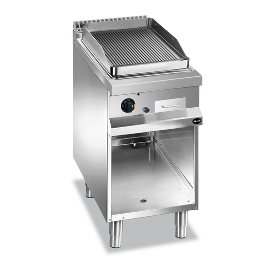
190FT1G Liscia (ferro) 190FT2G Rigata (ferro) 190FT3G ½ Rigata (ferro) 190FT4G Liscia (cromo) 190FT6G ½ Rigata (cromo) 190FT7G Liscia (compound) IDM-39603308100.tif 090FT1G Liscia (ferro) 090FT2G Rigata (ferro) 090FT4G Liscia (cromo) 090FT5G Rigata (cromo) 090FT7G Liscia (compound) IDM-39603307600.tif Liscia (ferro) 190FT72G... - Page 7 Organi principali A)Piastra di cottura: realizzata in diverse forme e materiali per far fronte alle diverse esigenze B)Scarico fumi (tipo A): per evacuare i fumi gene- rati dal bruciatore C)Tappo di scarico: per scaricare i residui di cottu- ra e convogliarli nella bacinella di raccolta D)Manopola comando bruciatore: per regolare l'alimentazione del gas al bruciatore E)Pulsante accensione: per accendere il bruciatore...
- Page 8 SEGNALI DI SICUREZZA E INFORMAZIONE L'illustrazione indica la posizione dei segnali applicati. A)Targa identificazione costruttore e apparec- chiatura. B)Pericolo di scottatura: fare attenzione alle su- perfici calde. C)Pericolo generico: durante il lavaggio dell'appa- recchiatura non dirigere getti d'acqua in pressio- ne sulle parti interne.
-
Page 9: Sicurezza
SICUREZZA NORME PER LA SICUREZZA Il costruttore, in fase di progettazione e costruzione, Per mantenere l'igiene e proteggere gli alimenti la- ha posto particolare attenzione agli aspetti che pos- vorati da tutti i fenomeni di contaminazione, è ne- sono provocare rischi alla sicurezza e alla salute cessario pulire accuratamente gli elementi che delle persone che interagiscono con l'apparecchia- vengono a contatto direttamente o indirettamente... -
Page 10: Uso E Funzionamento
USO E FUNZIONAMENTO RACCOMANDAZIONI PER L’USO Importante L'incidenza degli infortuni derivanti cipali. Attuare solo gli usi previsti dal co- dall'uso di apparecchiature dipende da struttore manomettere nessun molti fattori che non sempre si riescono a dispositivo per ottenere prestazioni diverse prevenire e controllare. - Page 11 ACCENSIONE E SPEGNIMENTO BRUCIATORE Per l'accensione e lo spegnimento procedere nel modo indicato per entrambi i bruciatori. Accensione Alla prima accensione lavare la piastra per togliere il grasso protettivo ed ogni eventuale impurità, quindi accendere l'apparecchiatura ed effettuare un preri- scaldamento di circa 2 ore alla temperatura di 195 °C.
- Page 12 RIPRISTINO APPARECCHIATURA In caso di intervento del termostato di sicurezza è necessario ripristinare le condizioni iniziali di funzio- namento dell'apparecchiatura nel modo indicato. È possibile effettuare questa operazione solo per le apparecchiature con piastra cromata. 1 - Premere il pulsante (A) del termostato di sicu- rezza intervenuto per riattivare l'alimentazione del gas.
- Page 13 MONTAGGIO PROLUNGA SCARICO RESIDUI Per questa operazione procedere nel modo indicato. 1 - Chiudere il rubinetto alimentazione gas. 2 - Agire sull'interruttore sezionatore dell'apparec- chiatura per disattivare l'allacciamento alla li- nea elettrica principale. 3 - Sfilare le manopole (A). 4 - Svitare le viti (B) e smontare il cruscotto (C). 5 - Inserire la prolunga scarico residui (D) nel tubo di scarico (E) e fissarlo con il dado (F).
- Page 14 Montaggio guida su telaio di appoggio 5 - Montare la guida bacinella (A) con le viti (B) ed inserire la bacinella di raccolta (C). IDM-39616103100.tif Montaggio guida su trave di sostegno 6 - Montare il "Kit copertura top" (D). 7 - Montare la guida bacinella (A) con le viti (B) ed inserire la bacinella di raccolta (C).
-
Page 15: Manutenzioni
INATTIVITÀ PROLUNGATA DELL’APPARECCHIATURA Se l'apparecchiatura rimane inattiva per un lungo 4 - Eseguire tutte le operazioni di manutenzione. tempo, procedere nel modo indicato. 5 - Ricoprire l'apparecchiatura con un involucro e 1 - Chiudere il rubinetto alimentazione gas. lasciare alcune fessure per la circolazione 2 - Pulire accuratamente l'apparecchiatura e le dell'aria. - Page 16 PULIZIA APPARECCHIATURA Se si considera che l'apparecchiatura è utilizzata 3 - Pulire gli accessori dopo l'uso, con uno sgras- per la preparazione di prodotti alimentari per l'uo- sante idoneo. Si consiglia il lavaggio in lavasto- mo, è necessario prestare particolare cura a tutto viglie.
- Page 17 5 - Rimuovere il tappo (B) per scaricare l'acqua Importante dalla piastra. 6 - Togliere la bacinella di raccolta (C) e svuotarla. Risciacquare accuratamente la piastra di 7 - Pulire accuratamente la piastra con una spu- cottura per rimuovere ogni residuo del de- gna, risciacquare abbondantemente ed asciu- tergente sgrassante ed evitare la formazio- gare.
-
Page 18: Guasti
GUASTI RICERCA GUASTI L'apparecchiatura, prima della messa in servizio, è per tutti gli altri è richiesta una precisa competenza stata preventivamente collaudata. Le informazioni di tecnica o particolari capacità e quindi devono essere seguito riportate hanno lo scopo di aiutare l'identifica- eseguiti esclusivamente da personale qualificato con zione e correzione di eventuali anomalie e disfunzioni esperienza riconosciuta e acquisita nel settore speci-... -
Page 19: Movimentazione E Installazione
MOVIMENTAZIONE E INSTALLAZIONE RACCOMANDAZIONI PER LA MOVIMENTAZIONE E INSTALLAZIONE Importante Eseguire la movimentazione e l'installazio- ste operazioni dovrà, se necessario, orga- ne nel rispetto delle informazioni fornite dal nizzare “piano sicurezza” costruttore e riportate direttamente sull'im- salvaguardare l'incolumità delle persone ballo, sull'apparecchiatura e nelle istruzioni direttamente coinvolte. - Page 20 MOVIMENTAZIONE E SOLLEVAMENTO L'apparecchiatura può essere movimentata con un dispositivo di sollevamento a forche o a gancio di portata adeguata. Prima di effettuare questa opera- zione, controllare la posizione del baricentro del ca- rico. Importante Nell'inserire il dispositivo di sollevamento, fare attenzione al tubo di alimentazione gas.
- Page 21 MONTAGGIO APPARECCHIATURE IN BATTERIA Per montare le apparecchiature in batteria (fianco a fianco) procedere nel modo indicato. 1 - Sfilare le manopole (A). 2 - Svitare le viti (B) e smontare i cruscotti (C). 3 - Smontare, se presente, il supporto “ferma la- na”.
- Page 22 ALLACCIAMENTO GAS Importante Chi è autorizzato ad effettuare tale operazio- ne deve possedere capacità ed esperienza acquisita e riconosciuta nel settore specifico, dovrà eseguire l'allacciamento a regola d'arte e tenere conto di tutti i requisiti normativi e le- gislativi. Ad allacciamento completato, prima di rendere operativa l'attrezzatura, si dovrà...
- Page 23 ALLACCIAMENTO ELETTRICO 2 - Sfilare le manopole (B). 3 - Svitare le viti (C) e smontare il cruscotto (D). Importante 4 - Collegare l'interruttore sezionatore (A) alla L'allacciamento deve essere effettuato da morsettiera (E) dell'apparecchiatura come indi- personale autorizzato e qualificato, nel ri- cato in figura e nello schema elettrico in fondo spetto delle leggi vigenti in materia e con al manuale.
-
Page 24: Regolazioni
4 - Rimuovere l'adesivo applicato sulla targhetta di identificazione e applicare quello nuovo per evi- denziare il gas in uso. Importante Ad operazione ultimata, accertarsi che non vi siano fuoriuscite di gas o anomalie di funzionamento. IDM-3960200250.tif COLLAUDO APPARECCHIATURA 3 - Verificare la regolare accensione e combustione Importante del bruciatore. -
Page 25: Sostituzione Parti
REGOLAZIONE ARIA PRIMARIA BRUCIATORE Per questa operazione procedere nel modo indicato. 1 - Chiudere il rubinetto alimentazione gas. 2 - Sfilare le manopole (A). 3 - Svitare le viti (C) e smontare il cruscotto (B). 4 - Allentare la vite di bloccaggio (D). 5 - Posizionare la boccola (E) in battuta, alla di- stanza (F) riportata in tabella. - Page 26 SOSTITUZIONE UGELLO BRUCIATORE Per questa operazione procedere nel modo indica- 1 - Chiudere il rubinetto alimentazione gas. 2 - Sfilare le manopole (A). 3 - Svitare le viti (B) e smontare il cruscotto (C). 4 - Svitare l'ugello (D) e sostituirlo con quello adat- to al tipo di gas utilizzato (vedi tabella in fondo al manuale).
- Page 27 CONTENTS ref. chapters page 1 GENERAL INFORMATION ..........2 2 TECHNICAL INFORMATION ..........4 3 SAFETY ................7 PART 4 USE AND OPERATION ............. 8 5 SERVICING ..............13 6 FAULT ................16 7 HANDLING AND INSTALLATION ........17 8 ADJUSTMENTS ............... 22 9 REPLACING PARTS ............
-
Page 28: General Information
GENERAL INFORMATION INFORMATION FOR THE READER To find the specific topics of interest to you quickly, part: contains all the information neces- refer to the index at the start of the manual. sary for special categories of reader, i.e. all This manual is subdivided into two parts. - Page 29 IDENTIFICATION OF CONSTRUCTOR AND APPLIANCE ) Rated power (kW) The nameplate shown here is fitted directly to the ) Gas consumption appliance. It contains references and all essential ) Testing gas indicator frame information for operating safety. ) Voltage (V) Extra nameplate ) Frequency (Hz) ) Country of use...
-
Page 30: Technical Information
190FT1G Smooth (iron) 190FT2G Ribbed (iron) 190FT3G ½ Ribbed (iron) 190FT4G Smooth (chromium) 190FT6G ½ Ribbed (chromium) 190FT7G Smooth (Compound) IDM-39603308100.tif 090FT1G Smooth (iron) 090FT2G Ribbed (iron) 090FT4G Smooth (chromium) 090FT5G Ribbed (chromium) 090FT7G Smooth (Compound) IDM-39603307600.tif Smooth (iron) 190FT72G... - Page 31 Main Parts A)Cooking plate: produced in a variety of shapes and materials to meet the different requirements B)Fume exhaust vent (Type A): for removal of the fumes generated by the burner C)Drain plug: for draining cooking residues into the drip tray D)Burner control knob: controls the supply of gas to the burner E)Ignition button: switches the burner on...
- Page 32 SAFETY AND INFORMATION SIGNS The illustration shows the position of the signs provided. A)Nameplate with manufacturer and appliance data. B)Burn hazard: watch out for hot surfaces. C)General hazard: when washing the appliance do not point pressurised water jets at internal parts. D)General hazard: read the manual carefully before carrying out any procedure.
-
Page 33: Safety
SAFETY SAFETY REGULATIONS During design and construction, the constructor has To maintain hygiene and protect the food proc- paid special attention to factors which may cause essed from all forms of contamination, all elements risks to the health and safety of the people interact- in direct or indirect contact with foodstuffs and all ing with the appliance. -
Page 34: Use And Operation
USE AND OPERATION RECOMMENDATIONS FOR USE Important The rate of accidents deriving from the use of tions. Use only as intended by the constructor appliances depends on many factors which and never tamper with any device to obtain cannot always be foreseen and controlled. performance levels outside the rated specifi- Some accidents may be caused by unpredict- cations. - Page 35 SWITCHING THE BURNER ON AND OFF The lighting and turning off procedure is as de- scribed below for both burners. Lighting The first time the griddle is switched on, wash the plate to remove the protective grease and any dirt, then switch on the appliance and preheat it for about 2 hours at the temperature of 195°C.
- Page 36 RESETTING THE APPLIANCE If the safety thermostat is tripped, the appliance has to be restored to the initial working conditions as fol- lows. This operation is only possible on appliances with chromium-plated. 1 - Press the button (A) of the safety thermostat tripped to restore the gas supply.
- Page 37 FITTING THE RESIDUE DRAIN EXTENSION To carry out this operation, proceed as follows. 1 - Turn off the gas supply tap. 2 - Cut off the mains electricity supply using the ap- pliance's master switch. 3 - Pull off the knob (A). 4 - Undo the screws (B) and remove the control panel (C).
- Page 38 Fitting the runner on a supporting frame 5 - Fit the drip tray runner (A) with the screws (B) and insert the drip tray (C). IDM-39616103100.tif Fitting the runner on a supporting beam 6 - Fit the "griddle cover kit" (D). 7 - Fit the drip tray runner (A) with the screws (B) and insert the drip tray (C).
-
Page 39: Servicing
LENGTHY DOWNTIMES OF APPLIANCE If the appliance is to be out of use for a lengthy pe- 3 - Spread a film of edible oil over the stainless riod, proceed as follows. steel surfaces. 1 - Turn off the gas supply tap. 4 - Carry out all the servicing procedures. - Page 40 CLEANING INSTRUCTIONS Since the appliance is used for preparing foods for Caution - warning human consumption, special care must be paid to Never use products containing substances everything relating to hygiene, and the appliance harmful or hazardous for health (solvents, pe- and the entire surrounding environment must con- troleum spirits, etc.).
- Page 41 5 - Remove the plug (B) to drain the water from the Important plate. Rinse the cooking plate thoroughly to re- 6 - Remove the drip tray (C) and drain it. move all residues of the degreasing deter- 7 - Clean the plate thoroughly with a sponge, rinse gent, and prevent stains and marks from with plenty of water and dry.
-
Page 42: Fault
FAULT TROUBLESHOOTING The appliance has been tested before being put The user can solve some of these problems him- into service. The information provided below is in- self, but for others specific technical knowledge or tended to assist in the identification and correction skill is required, and so they must only be carried of any anomalies and malfunctions which might oc- out by qualified staff with recognised experience ac-... -
Page 43: Handling And Installation
HANDLING AND INSTALLATION RECOMMENDATIONS FOR HANDLING AND INSTALLATION Important When handling and installing the appliance use. If necessary, the person authorised to comply with the information provided by carry out these operations must organise a the constructor directly on the packaging, "safety plan"... - Page 44 HANDLING AND LIFTING The appliance can be handled using fork-lift or hook equipment of suitable load-carrying capacity. Be- fore lifting, check the position of the load's centre of gravity. Important When engaging with the lifting equipment, watch out for the gas supply pipe. IDM-39603309300.tif INSTALLATION OF THE APPLIANCE All installation stages must be considered right from...
- Page 45 ASSEMBLY APPLIANCES IN BANKS To assemble appliances in banks (side by side) proceed as described below. 1 - Pull off the knob (A). 2 - Undo the screws (B) and remove the control panels (C). 3 - Remove the "insulation retainer" , if fitted. 4 - Apply masking tape to the edges to be placed side by side.
- Page 46 GAS CONNECTION Important Those authorised to carry out this opera- tion must have experience acquired and certified in the specific sector, must make the connection to the proper standards, and must comply with all the relevant regu- lations and legislation. Once the connec- tion has been made, before the appliance is put into operation a general check must be made to ensure there are no gas leaks.
- Page 47 ELECTRICAL CONNECTION 2 - Pull off the knob (B). 3 - Undo the screws (C) and remove the control Important panel (D). The connection must be made by author- 4 - Connect the circuit-breaker (A) to the terminal ised, skilled personnel, in accordance with board (E) of the appliance as shown in the dia- the relevant legal requirements, using ap- gram and in the electrical system diagram at...
-
Page 48: Adjustments
4 - Remove the sticker from the nameplate and ap- ply the new one to identify the gas being used. Important On completion of the operation, make sure that there are no gas leaks or malfunctions. IDM-3960200250.tif TESTING OF THE APPLIANCE 3 - Check that the burner is switching on correctly Important and its combustion. -
Page 49: Replacing Parts
ADJUSTING BURNER PRIMARY AIR To carry out this operation, proceed as follows. 1 - Turn off the gas supply tap. 2 - Pull off the knob (A). 3 - Undo the screws (C) and remove the control panel (B). 4 - Undo the locking screw (D). 5 - Set the bush (E) in contact at the distance (F) shown in the table. - Page 50 REPLACEMENT OF THE BURNER NOZZLE To carry out this operation, proceed as follows. 1 - Turn off the gas supply tap. 2 - Pull off the knob (A). 3 - Undo the screws (B) and remove the control panel (C). 4 - Unscrew the nozzle (D) and replace it with the one suitable for the type of gas in use (see table at back of manual).
- Page 51 INHALTSVERZEICHNIS Ref. Kapitel Seite 1 ALLGEMEINES ..............2 2 TECHNISCHE INFORMATIONEN ........4 3 SICHERHEIT ..............7 1. TEIL 4 GEBRAUCH UND BETRIEB ..........8 5 WARTUNG ............... 13 6 DEFEKTE ................. 16 7 HANDHABUNG UND INSTALLATION ......17 8 EINSTELLUNGEN ............22 9 AUSTAUSCH VON BAUTEILE ........
-
Page 52: Allgemeines
ALLGEMEINES INFORMATIONEN FÜR DEN LESER Konsultieren Sie das Sachregister, das am Anfang 2. Teil: Diese Informationen wenden sich an des Handbuchs zu finden ist, um leichter unter be- eine bestimmte Zielgruppe. Sie sind für er- stimmten Themen von besonderem Interesse fahrene Bediener bestimmt, die für Handha- nachschlagen zu können. - Page 53 TYPENSCHILD FÜR HERSTELLER UND GERÄT ) Angabe der Leistung (Kw) Das abgebildete Typenschild wird direkt auf dem ) Gasverbrauch Gerät aufgebracht. Es enthält sämtliche Angaben ) ITestgasanzeige und Hinweise, die für den sicheren Betrieb unerläs- ) Spannung (V) slich sind. ) Frequenz (Hz) Ergänzungsschild ) Benutzerland...
-
Page 54: Technische Informationen
190FT1G Glatte (Eisen) 190FT2G 190FT3G Gerillte (Eisen) ½ Gerillte (Eisen) 190FT4G Glatte (Chrom) 190FT6G ½ Gerillte (Chrom) 190FT7G Glatte (Verbundstoff) IDM-39603308100.tif 090FT1G Glatte (Eisen) 090FT2G Gerillte (Eisen) 090FT4G 090FT5G Glatte (Chrom) Gerillte (Chrom) 090FT7G Glatte (Verbundstoff) IDM-39603307600.tif Glatte (Eisen) 190FT72G... - Page 55 Hauptorgane A)Bratplatte: Ausgeführt in unterschiedlichen For- men und Materialien, um den verschiedenen An- forderungen entgegenzukommen B)Rauchabzug (Typ A): zum Abführen der vom Bren- ner erzeugten Rauchgase C)Ablassverschluss: zum Ablassen der Bratrück- stände in den Auffangbehälter D)Bedienknebel Brenner: um die Gaszufuhr zu den Brennern einzustellen E)Taste Zündung: Zum Zünden des Brenners.
- Page 56 SICHERHEITSHINWEISE UND INFORMATIONEN Die Abbildung zeigt die Anordnung der aufgekleb- ten Sicherheitshinweise. A)Typenschild mit Angabe des Herstellers und der Gerätekenndaten. B)Verbrennungsgefahr: Vorsicht vor heißen Flächen. C)Allgemeine Gefahr: Beim Waschen des Geräts den Wasserstrahl nicht direkt auf die inneren Teile richten. D)Allgemeine Gefahr: Vor Ausführung irgendeines Eingriffs zuerst das Handbuch aufmerksam lesen.
-
Page 57: Sicherheit
SICHERHEIT SICHERHEITSVORSCHRIFTEN Der Hersteller hat bei Entwicklung und Fertigung tel müssen die Elemente, die direkt oder indirekt mit dieses Produkts besondere Sorgfalt auf Aspekte den Nahrungsmitteln in Berührung kommen sowie verwendet, die eine Gefahr für die Sicherheit und die angrenzenden Zonen, akkurat gereinigt wer- die Gesundheit der Personen, die dieses Gerät den. -
Page 58: Gebrauch Und Betrieb
GEBRAUCH UND BETRIEB EMPFEHLUNGEN FÜR DEN GEBRAUCH Wichtig Das Auftreten von Unfällen bei der Verwendung schränken Sie sich auf die vom Hersteller vorgese- von Geräten hängt von vielen Faktoren ab, die henen Verwendungszwecke, ohne Änderungen an nicht immer zu vermeiden und zu steuern sind. Ei- den Vorrichtungen vorzunehmen, um nicht vorge- nige Unfälle können von unvorhersehbaren Raum- sehene Leistungen herbeizuführen. - Page 59 EIN- UND AUSSCHALTEN DES BRENNERS Verfahren Sie zum Zünden und Abschalten der bei- den Brenner folgendermaßen: Zündung Zur ersten Inbetriebnahme die Platte waschen, um die Schutzölschicht und eventuelle Verunreinigungen zu entfernen. Dann das Gerät einschalten und rund 2 Stunden bei einer Temperatur von 195 °C vorheizen. 1 - Öffnen Sie den Gashahn.
- Page 60 RÜCKSETZEN DES GERÄTS Wenn der Sicherheitsthermostat anspricht, muss das Gerät in der angegebenen Weise wieder in den normalen Betriebszustand versetzt werden. Dieser Vorgang kann nur bei Geräten mit ver- chromter Platte ausgeführt werden. 1 - Den Taster (A) des ausgelösten Sicherheits- thermostaten drücken, um die Gaszufuhr wie- der freizugeben.
- Page 61 MONTAGE DER VERLÄNGERUNG ZUM ABLASSEN DER RÜCKSTÄNDE Für diesen Vorgang in der angegebenen Weise verfahren. 1 - Schließen Sie den Gaszufuhrhahn 2 - Das Gerät mit seinem Trennschalter vom Hauptstromnetz trennen. 3 - Den Schalter (A) abziehen. 4 - Drehen Sie die Schrauben (B) heraus und montieren Sie die Blende (C) ab.
- Page 62 Montage des Behältertragrahmens auf Stütz- rahmen 5 - Den Behältertragrahmen (A) mit den Schrau- ben (B) befestigen und den Auffangbehälter (C) einschieben. IDM-39616103100.tif Montage des Behältertragrahmens auf Träger 6 - Den "Bausatz Abdeckung Oberseite" (D) montieren. 7 - Den Behältertragrahmen (A) mit den Schrauben (B) befestigen und den Auffangbehälter (C) ein- schieben.
-
Page 63: Wartung
LÄNGERER STILLSTAND DES GERÄTS Verfahren Sie folgendermaßen, falls das Gerät län- 3 - Tragen Sie eine hauchdünne Schicht Lebens- gere Zeit nicht eingesetzt werden soll: mittelöl auf die Edelstahlflächen auf. 1 - Schließen Sie den Gaszufuhrhahn 4 - Führen Sie sämtliche Wartungsarbeiten aus. 2 - Reinigen Sie das Gerät und die angrenzenden 5 - Das Gerät mit einer Schutzhülle abdecken;... - Page 64 REINIGUNG DES GERÄTS Da das Gerät zur Zubereitung von Speisen für den Vorsicht - Achtung Menschen eingesetzt wird, ist besondere Sorgfalt Verwenden Sie keine Produkte, die Stoffe ent- auf die Hygiene geboten. Das Gerät und dessen halten, welche für die menschliche Gesund- näheres Umfeld müssen konstant sauber gehalten heit schädlich...
- Page 65 5 - Den Verschluss (B) entfernen, um das Wasser Wichtig abzulassen. 6 - Den Auffangbehälter (C) herausnehmen und Die Bratplatte sorgfältig spülen, um alle entleeren. Fettlöserrückstände zu entfernen und um 7 - Die Platte sorgfältig mit einem Schwamm reini- die Bildung von Flecken und Schlieren gen, gut nachspülen und trocknen.
-
Page 66: Defekte
DEFEKTE FEHLERSUCHE Vor der Inbetriebnahme wurde das Gerät einem vor- Einige dieser Probleme können vom Benutzer selbst läufigen Testlauf unterzogen. behoben werden; alle anderen erfordern präzise Fach- Die im Folgenden aufgeführten Informationen sollen Ih- kenntnisse oder besondere Fähigkeiten und dürfen da- nen dabei helfen, eventuelle Anomalien oder Funkti- her ausschließlich von qualifiziertem Personal mit onsstörungen, die während des Betriebs auftreten... -
Page 67: Handhabung Und Installation
HANDHABUNG UND INSTALLATION EMPFEHLUNGEN FÜR DIE INSTALLATION UND HANDHABUNG Wichtig Beachten Sie die Hinweise des Herstellers, nen autorisierte Person wird bei Bedarf die direkt auf der Verpackung, auf dem Ge- einen „Sicherheitsplan" aufstellen müssen, rät selbst oder in der Gebrauchsanweisung um die Unversehrtheit der direkt an dem zu finden sind, wenn Sie das Gerät handha- Vorgang beteiligten Personen zu gewähr-... - Page 68 HANDHABUNG UND HUB Das Gerät kann mit einem Hubmittel bewegt wer- den, das mit Gabeln oder Haken ausgestattet ist und die geeignete Traglast besitzt. Vor diesem Vor- gang ist der Schwerpunkt der Last zu überprüfen. Wichtig Achten Sie beim Einsatz des Hubmittels auf das Gaszufuhrrohr.
- Page 69 MONTAGE BEI REIHENAUFSTELLUNG Verfahren Sie folgendermaßen, um Geräte (neben- einander) in einer Reihe aufzustellen. 1 - Den Schalter (A) abziehen. 2 - Die Schrauben (B) ausschrauben und die Blen- den (C) ausbauen. 3 - Falls vorhanden, die Halterung der Dämmwolle ausbauen.
- Page 70 GASANSCHLUSS Wichtig Diese Arbeit darf nur von zugelassenen und erfahrenen Fachleuten ausgeführt wer- den. Der Anschluss muss fachgerecht und vorschriftsmäßig ausgeführt werden und allen einschlägigen gesetzlichen Bestim- mungen entsprechen. Nach Ausführung des Anschlusses muss vor der Inbetrieb- nahme des Geräts durch eine allgemeine Kontrolle sichergestellt werden, dass nir- IDM-39603309500.tif gends Gas austritt.
- Page 71 STROMANSCHLUSS 2 - Den Schalter (B) abziehen. 3 - Drehen Sie die Schrauben (C) heraus und montie- Wichtig ren Sie die Blende (D) ab. Der Anschluss muss von autorisiertem Fach- 4 - Den Trennschalter (A) nach den Angaben in der personal in Einklang mit den einschlägigen Abbildung und im Schaltplan am Ende des Hand- gesetzlichen Bestimmungen und unter Ver-...
-
Page 72: Einstellungen
4 - Entfernen Sie den alten Aufkleber vom Typen- schild und ersetzen Sie ihn mit dem neuen Auf- kleber, verwendeten Gastyp anzuzeigen. Wichtig Stellen Sie nach Abschluss dieses Vor- gangs sicher, dass kein Gas austritt und keine Funktionsstörungen auftreten. IDM-3960200250.tif TESTLAUF ZUR ABNAHME DES GERÄTS vor (siehe Seite 21). -
Page 73: Austausch Von Bauteile
EINSTELLUNG DER PRIMÄRLUFT DES BRENNERS Für diesen Vorgang in der angegebenen Weise verfahren. 1 - Schließen Sie den Gaszufuhrhahn 2 - Den Schalter (A) abziehen. 3 - Drehen Sie die Schrauben (C) heraus und montieren Sie die Blende (B) ab. 4 - Die Klemmschraube (D) lockern. - Page 74 AUSWECHSELN DER BRENNERDÜSE Für diesen Vorgang in der angegebenen Weise verfahren. 1 - Schließen Sie den Gaszufuhrhahn 2 - Den Schalter (A) abziehen. 3 - Drehen Sie die Schrauben (B) heraus und montieren Sie die Blende (C) ab. 4 - Schrauben Sie die Düse (D) heraus und erset- zen Sie sie mit dem für den betreffenden Gas- typ geeigneten Ersatzteil (siehe Tabelle am Ende des Handbuches).
- Page 75 INDEX réf. chapitres page 1 INFORMATIONS GÉNÉRALES ......... 2 2 INFORMATIONS TECHNIQUES ........4 3 SÉCURITÉ ................. 7 PARTIE 4 UTILISATION ET FONCTIONNEMENT ......8 5 ENTRETIEN ..............13 6 PANNES ................16 7 MANUTENTION ET INSTALLATION ....... 17 8 RÉGLAGES ..............22 9 REMPLACEMENT DE PIÈCES ........
- Page 76 INFORMATIONS GÉNÉRALES INFORMATIONS POUR LE LECTEUR Pour retrouver facilement les sujets qui vous inté- partie: elle contient toutes les informations ressent, consulter l’index analytique au début du nécessaires aux destinataires homogènes, manuel. c’est-à-dire tous les opérateurs experts et Ce manuel est divisé en deux parties. autorisés à...
- Page 77 IDENTIFICATION DU FABRICANT ET DE L’APPAREIL ) Puissance déclarée (kW) La plaque d’identification représentée, est appli- ) Consommation de gaz quée directement sur l'appareil. Elle reporte les ré- ) Indicateur du gaz d’essai férences et les indications indispensables à la ) Tension (V) sécurité.
- Page 78 190FT3G ½ Lisse (chrome) Rayée (chrome) 190FT4G 190FT6G ½ 190FT7G Lisse (matériau composite) IDM-39603308100.tif Lisse (fer) Rayée (fer) 090FT1G 090FT2G Lisse (chrome) Rayée (chrome) 090FT4G 090FT5G 090FT7G Lisse (matériau composite) IDM-39603307600.tif Lisse (fer) 190FT72G Lisse (matériau composite) + Rayée (fer)
- Page 79 Organes principaux A)Plaque de cuisson: réalisée en différentes for- mes et différents matériaux pour faire face à tou- tes les exigences B)Évacuation des fumées (Type A): pour évacuer les fumées générées par le brûleur C)Bouchon de vidange: pour évacuer les résidus de cuisson et les porter dans le bac de récolte D)Manette de commande du brûleur: pour régler l’alimentation du gaz au brûleur...
- Page 80 SIGNAUX DE SÉCURITÉ ET INFORMATION L’illustration indique la position des signaux appliqués. A)Plaque d'identification du fabricant et de l'ap- pareil. B)Risque de brûlure: attention aux surfaces chaudes. C)Risque générique: pendant le lavage de l’appareil ne pas diriger de jets d’eau sous pression sur les piè- ces intérieures.
- Page 81 SÉCURITÉ NORMES DE SÉCURITÉ Le fabricant, lors de la conception et de la fabrica- Pour maintenir l'hygiène et protéger les aliments de tion, a fait très attention aux aspects qui peuvent tous les phénomènes de contamination, il faut net- provoquer des risques à la sécurité et à la santé des toyer soigneusement les éléments qui sont en con- personnes qui interagissent avec l’appareil.
- Page 82 UTILISATION ET FONCTIONNEMENT RECOMMANDATIONS POUR L'UTILISATION Important L’incidence des accidents dérivant de l’utilisation et les fonctions principales. Utiliser seulement d’appareils dépend de beaucoup de facteurs que comme prévu par le fabricant et ne modifier aucun l’on ne peut pas toujours prévenir et contrôler. dispositif pour obtenir des performances différen- Certains accidents peuvent dépendre de facteurs tes de celles prévues.Avant l’utilisation, vérifier si...
- Page 83 ALLUMAGE ET EXTINCTION DU BRULEUR Pour l’allumage et l’extinction des brûleurs, procé- der comme suit pour les deux brûleurs. Allumage Au premier allumage, laver la plaque pour enlever la graisse de protection et toute impureté éventuel- le, puis allumer l'appareil et préchauffer pendant environ 2 heures à...
- Page 84 RÉTABLISSEMENT DES FONCTIONS DE L'APPAREIL Dans le cas d'intervention du thermostat de sécuri- té, il faut rétablir les conditions initiales de fonction- nement de l’appareil dans le mode indiqué. On ne peut effectuer cette opération que pour les appareils à plaque chromée. 1 - Appuyer sur le bouton (A) du thermostat de sécurité...
- Page 85 MONTAGE DE LA RALLONGE ÉVACUATION DES RÉSIDUS Pour cette opération, procéder comme suit. 1 - Fermer le robinet d’alimentation du gaz. 2 - Agir sur l'interrupteur sectionneur de l’appareil pour désactiver le branchement à la ligne élec- trique principale. 3 - Enlever la manette (A). 4 - Dévisser les vis (B) et démonter le tableau de commandes (C).
- Page 86 Montage du guide sur le bâti d’appui 5 - Monter le guide du bac (A) avec les vis (B) et introduire le bac de récolte (C). IDM-39616103100.tif Montage du guide sur la traverse de soutien 6 - Monter le « Kit de couverture du dessus » (D). 7 - Monter le guide du bac (A) avec les vis (B) et introduire le bac de récolte (C).
- Page 87 INUTILISATION PROLONGÉE DE L’APPAREIL Si l'appareil reste inactif pendant longtemps, procé- 3 - Étaler un voile d’huile alimentaire sur les surfa- der comme suit. ces en acier inox. 1 - Fermer le robinet d’alimentation du gaz. 4 - Exécuter toutes les opérations d’entretien. 2 - Nettoyer soigneusement l'appareil et les zones 5 - Recouvrir l'appareil d'une protection et laisser limitrophes...
- Page 88 NETTOYAGE DE L’APPAREIL Étant donné que l'appareil est utilisé pour la prépa- 3 - Nettoyer les accessoires après leur utilisation avec un dégraissant approprié. Le lavage en ration de produits alimentaires pour l'homme, il faut lave-vaisselle est conseillé. faire attention à tout ce qui concerne l'hygiène ; l'appareil et tout ce qui l'entoure doivent toujours Attention être très propres.
- Page 89 5 - Enlever le bouchon (B) pour évacuer l'eau de la Important plaque. 6 - Enlever le bac de récolte (C), le vider. Bien rincer la plaque de cuisson pour enle- 7 - Nettoyer soigneusement la plaque avec une ver tout résidu de détergent dégraissant et éponge, rincer abondamment et essuyer.
- Page 90 PANNES DÉPANNAGE Avant sa mise en service, l’appareil a été essayé. l’utilisateur, pour tous les autres il faut une compé- Les informations reportées ci-après ont pour but tence technique précise capacités d’aider à l'identification et à la correction d’éven- particulières ; ils doivent donc être exécutés exclu- tuels pannes et dysfonctionnements qui pourraient sivement par du personnel qualifié...
- Page 91 MANUTENTION ET INSTALLATION RECOMMANDATIONS POUR LA MANUTENTION ET L’INSTALLATION Important Effectuer la manutention et l’installation en effectuer ces opérations devra, si nécessai- respectant les informations fournies par le re, organiser un « plan de sécurité » pour fabricant, reportées directement sur l’em- sauvegarder la sécurité...
- Page 92 MANUTENTION ET LEVAGE L'appareil peut être manutentionné avec un dispo- sitif de levage à fourches ou à crochet d’une capa- cité de charge appropriée. Avant d’effectuer cette opération, contrôler la position du centre de gravité de la charge. Important En introduisant le dispositif de levage, faire attention au tuyau d’alimentation du gaz.
- Page 93 MONTAGE DES APPAREILS EN BATTERIE Pour monter les appareils en batterie (les uns à côté des autres), procéder comme suit. 1 - Enlever la manette (A). 2 - Dévisser les vis (B) et démonter les tableaux de commandes (C). 3 - Démonter, s’il est présent, le support de bloca- ge de la laine.
- Page 94 RACCORDEMENT DU GAZ Important La personne autorisée à effectuer cette opération devra avoir les capacités et l’ex- périence acquise et reconnue dans le sec- teur spécifique ; elle devra effectuer le raccordement dans les règles de l’art et te- nir compte de toutes les exigences impo- sées par les normes et les lois.
- Page 95 BRANCHEMENT ÉLECTRIQUE 2 - Enlever la manette (B). Important 3 - Dévisser les vis (C) et démonter le tableau de Le branchement doit être fait par du per- commandes (D). sonnel autorisé et qualifié, conformément 4 - Connecter l'interrupteur sectionneur (A) au bor- aux lois en vigueur à...
- Page 96 4 - Enlever l’adhésif collé sur la plaque d’identifica- tion et appliquer le nouveau pour mettre en évi- dence le gaz utilisé. Important Lorsque l’opération est terminée, s’assurer qu’il n’y ait pas de fuites de gaz ou d’ano- malies de fonctionnement. IDM-3960200250.tif ESSAI DE L’APPAREIL 3 - Vérifier l'allumage régulier et la combustion du...
- Page 97 RÉGLAGE AIR PRIMAIRE DU BRÛLEUR Pour cette opération, procéder comme suit. 1 - Fermer le robinet d’alimentation du gaz. 2 - Enlever la manette (A). 3 - Dévisser les vis (C) et démonter le tableau de commandes (B). 4 - Desserrer la vis de blocage (D). 5 - Placer la douille (E) en butée, à...
- Page 98 REMPLACEMENT DE LA BUSE DU BRULEUR Pour cette opération, procéder comme suit. 1 - Fermer le robinet d’alimentation du gaz. 2 - Enlever la manette (A). 3 - Dévisser les vis (B) et démonter le tableau de commandes (C). 4 - Dévisser la buse (D) et la remplacer par celle adaptée au type de gaz utilisé...
- Page 99 ÍNDICE ref. capítulos pág 1 INFORMACIONES DE CARÁCTER GENERAL ....2 2 INFORMACIONES DE CARÁCTER TÉCNICO ....4 3 SEGURIDAD ..............7 PARTE 4 USO Y FUNCIONAMIENTO ..........8 5 MANTENIMIENTO ............13 6 AVERÍAS ................16 7 DESPLAZAMIENTO E INSTALACIÓN ......17 8 REGULACIONES .............
-
Page 100: Informaciones De Carácter General
INFORMACIONES DE CARÁCTER GENERAL INFORMACIONES PREVIAS Para ubicar fácilmente los temas específicos de in- parte: contiene todas las informaciones terés, consúltese el índice analítico que se encuen- necesarias para destinatarios homogéneos, tra al inicio del manual. esto es, todos los operadores expertos y au- Este manual comprende dos partes. - Page 101 IDENTIFICACIÓN FABRICANTE Y EQUIPO ) Potencia declarada (kW) La placa de identificación fijada directamente en el ) Consumo de gas equipo reproduce todas las referencias e indicacio- ) Indicador gas prueba de funcionamiento nes indispensables para la seguridad de servicio. ) Tensión (V) Placa complementaria ) Frecuencia (Hz)
-
Page 102: Informaciones De Carácter Técnico
Lisa (hierro) 190FT2G 190FT3G Ranurada (cromo) ½ Ranurada (hierro) 190FT4G Lisa (cromo) 190FT6G ½ Ranurada (cromo) 190FT7G Lisa (material compuesto) IDM-39603308100.tif 090FT1G Lisa (hierro) 090FT2G Ranurada (hierro) 090FT4G Lisa (cromo) 090FT5G Ranurada (cromo) 090FT7G Lisa (material compuesto) IDM-39603307600.tif Lisa (hierro) - Page 103 Órganos principales A)Plancha de cocción: realizada en diferentes for- mas y materiales para satisfacer cada requeri- miento específico B)Salida de humos (Tipo A): para evacuar los humos generados por el quemador C)Tapón de descarga: para descargar los residuos de cocción y conducirlos a la respectiva cubeta de recogida D)Mando del quemador: para regular la alimentación de gas al quemador...
- Page 104 SEÑALIZACIONES DE SEGURIDAD E INFORMACIÓN La ilustración indica la posición de las señalizacio- nes fijadas en el equipo. A)Placa de identificación fabricante y aparato. B)Peligro de quemaduras: prestar atención a las su- perficies calientes. C)Peligro genérico: durante el lavado del aparato no dirigir chorros de agua a presión hacia sus partes in- ternas.
-
Page 105: Seguridad
SEGURIDAD NORMAS DE SEGURIDAD Durante las fases de diseño y producción el fabri- Para mantener la higiene y proteger los alimentos cante ha prestado especial atención a los factores trabajados respecto de cualquier fenómeno de con- que pueden provocar riesgos en cuanto a seguri- taminación, es necesario limpiar prolijamente los dad y salud de las personas que interactúan con el elementos que entran en contacto directa o indirec-... -
Page 106: Uso Y Funcionamiento
USO Y FUNCIONAMIENTO RECOMENDACIONES DE USO Importante El porcentaje de accidentes derivados del uso de principales. Se deben ejecutar sólo operaciones equipos depende de muchos factores que no propias de los usos previstos por el fabricante. No siempre se logran prevenir y controlar. Algunos alterar los equipos con el fin de obtener prestacio- accidentes pueden depender de factores ambien- nes diferentes de las previstas. - Page 107 ENCENDIDO Y APAGADO DEL QUEMADOR Para el encendido y el apagado, efectuar en ambos quemadores las siguientes operaciones. Encendido Al efectuar el primer encendido lavar la plancha a fin de eliminar la grasa protectora y toda otra even- tual impureza. A continuación encender el aparato y efectuar un precalentamiento de aproximada- mente 2 horas a temperatura de 195 °C.
- Page 108 REACTIVACIÓN APARATO En caso de intervención del termostato de segu- ridad será necesario restablecer las condiciones iniciales de funcionamiento del aparato, proce- diendo para ello de la manera que a continuación se indica. Esta operación sólo puede ser efectua- da en aparatos con plancha cromada. 1 - Presionar el botón (A) del termostato de segu- ridad que ha intervenido a fin de restablecer la alimentación del gas.
- Page 109 MONTAJE ALARGADOR DESCARGA RESIDUOS Para efectuar esta operación, aplicar las siguientes instrucciones. 1 - Cerrar el grifo de alimentación del gas. 2 - Con el interruptor aislador del aparato desacti- var la conexión a la línea eléctrica principal. 3 - Retirar el mando (A). 4 - Desenroscar los tornillos (B) y desmontar el ta- blero de instrumentos (C).
- Page 110 Montaje guía en bastidor de apoyo 5 - Montar la guía cubeta (A) mediante los tornillos (B) e instalar la cubeta de recogida (C). IDM-39616103100.tif Montaje guía en barra de soporte 6 - Montar el "Kit cobertura top" (D). 7 - Montar la guía cubeta (A) mediante los tornillos (B) e instalar la cubeta de recogida (C).
-
Page 111: Mantenimiento
PERÍODO PROLONGADO DE INACTIVIDAD DEL EQUIPO En caso de que el equipo deba permanecer inacti- 3 - Esparcir sobre las superficies de acero inoxida- vo durante un período prolongado de tiempo, se ble una capa delgada de aceite comestible. deberán efectuar las siguientes operaciones. 4 - Efectuar todas las operaciones de manteni- 1 - Cerrar el grifo de alimentación del gas. - Page 112 LIMPIEZA APARATO Atendida la circunstancia de que el equipo es utili- 3 - Limpiar los accesorios después del uso utili- zado para la preparación de productos alimenticios zando un desengrasante adecuado. Se acon- para el consumo humano, es necesario prestar es- seja efectuar el lavado en lavavajillas.
- Page 113 5 - Retirar el tapón (B) para descargar el agua pre- Importante sente en la plancha. 6 - Retirar la cubeta de recogida (C) y vaciarla. Es importante enjuagar cuidadosamente la 7 - Limpiar cuidadosamente la plancha con una plancha de cocción a fin de eliminar todo esponja, enjuagar abundantemente y secar.
-
Page 114: Averías
AVERÍAS BÚSQUEDA DE AVERÍAS Antes de la puesta en servicio, el equipo ha sido so- den ser resueltos por el usuario, pero otros requie- metido a prueba de funcionamiento. competencia técnica precisa Las siguientes informaciones tienen por objeto faci- determinadas capacidades, razón por la cual de- litar la identificación y corrección de eventuales ben ser resueltos exclusivamente por personal ca- anomalías y disfunciones que podrían presentarse... -
Page 115: Desplazamiento E Instalación
DESPLAZAMIENTO E INSTALACIÓN RECOMENDACIONES PARA EL DESPLAZAMIENTO Y LA INSTALACIÓN Importante Efectuar el desplazamiento e instalación rizada para efectuar estas operaciones de- respetando las indicaciones proporciona- berá, si fuera necesario, organizar un "plan das por el fabricante, reproducidas directa- de seguridad", a fin de salvaguardar la in- mente sobre el embalaje, en el equipo y en columidad de las personas directamente las instrucciones de uso. - Page 116 DESPLAZAMIENTO Y ELEVACIÓN El equipo puede ser desplazado con un equipo de elevación de horquillas o de gancho, de capacidad adecuada. Para ejecutar esta operación se debe controlar atentamente el centro de gravedad de la carga. Importante Proceder con cautela al introducir el equipo de elevación a fin de no dañar el tubo de ali- mentación del gas.
- Page 117 MONTAJE DE EQUIPOS EN BATERÍA Para montar los equipos en batería (uno al lado del otro) aplicar las siguientes instrucciones. 1 - Retirar el mando (A). 2 - Desenroscar los tornillos (B) y desmontar los paneles de mando (C). 3 - En caso de estar presente, desmontar el sopor- te "fijador lana".
- Page 118 ENLACE GAS Importante El personal autorizado para ejecutar esta operación debe poseer capacidad y haber adquirido experiencia efectiva en el sector específico; la conexión deberá ejecutarse respetando rigurosamente todos los requi- sitos establecidos por las normativas vigen- tes. Una vez efectuada la conexión, antes de poner en funcionamiento el aparato se de- berá...
- Page 119 CONEXIÓN ELÉCTRICA 2 - Retirar el mando (B). 3 - Desenroscar los tornillos (C) y desmontar el ta- Importante blero de instrumentos (D). La conexión deberá asignarse al personal 4 - Conectar el interruptor seccionador (A) a la autorizado y experto, que deberá respetar las bornera (E) del aparato de la manera ilustrada leyes vigentes en materia y utilizar siempre en la figura y en el esquema eléctrico al final del...
-
Page 120: Regulaciones
4 - Retirar el adhesivo presente en la placa de identificación y fijar el nuevo adhesivo relativo al tipo de gas a utilizar. Importante Una vez concluida la operación, controlar que no haya fugas de gas o anomalías de funcionamiento. IDM-3960200250.tif PRUEBA DE FUNCIONAMIENTO DEL EQUIPO 3 - Controlar el correcto encendido y combustión... -
Page 121: Sostitución De Piezas
REGULACIÓN AIRE PRIMARIO QUEMADOR Para efectuar esta operación, aplicar las siguientes instrucciones. 1 - Cerrar el grifo de alimentación del gas. 2 - Retirar el mando (A). 3 - Desenroscar los tornillos (C) y desmontar el ta- blero de instrumentos (B). 4 - Aflojar el tornillo de fijación (D). - Page 122 SUSTITUCIÓN INYECTOR QUEMADOR Para efectuar esta operación, aplicar las siguientes instrucciones. 1 - Cerrar el grifo de alimentación del gas. 2 - Retirar el mando (A). 3 - Desenroscar los tornillos (B) y desmontar el ta- blero de instrumentos (C). 4 - Desenroscar el inyector (D) y sustituirlo por otro que sea adecuado para el tipo de gas utilizado (véase tabla al final del manual).
- Page 124 Consommation de gaz - Consumo de gas Bruleur - Quemadores Model - Modelle Stromanschluss Modèle - Modelo Branchement électrique 10 kW Conexión eléctrica (Min. 4,2 kW) G25.1 090FT1G 090FT2G 0,6W/230V1~N 090FT4G N. 1 1,06 m /h 1,23 m 0,79 Kg/h 0,78 Kg/h 50/60 Hz...
- Page 125 Bruciatori Consumo gas Allacciamento elettrico Burner - Brenner Gas consumption - Gasverbrauch Modello Electrical connection Consommation de gaz - Consumo de gas Bruleur - Quemadores Model - Modelle Stromanschluss Modèle - Modelo Branchement électrique 10 kW Conexión eléctrica (Min. 4,2 kW) G25.1 190FT1G 190FT2G...
- Page 126 Bruciatori Consumo gas Allacciamento elettrico Burner - Brenner Gas consumption - Gasverbrauch Modello Electrical connection Consommation de gaz - Consumo de gas Bruleur - Quemadores Model - Modelle Stromanschluss Modèle - Modelo Branchement électrique 10 kW Conexión eléctrica (Min. 4,2 kW) G25.1 190FT15G 0,6W/230V1~N...
- Page 127 SCHEMA ELETTRICO 090FTG - ELECTRICAL SYSTEM DIAGRAM 090FTG ELEKTRISCHER SCHALTPLAN 090FTG - SCHÉMA ÉLECTRIQUE 090FTG ESQUEMA ELÉCTRICO 090FTG IDM-39614701800.tif 1) Morsettiera - Terminal board - Klemmenbrett - Plaque à bornes - Regleta de 3) Gruppo accensione - Ignition unit - Baugruppe Zündung - Groupe d’allumage conexión - Unidad de encendido 2) Pulsante accensione - Ignition button - Taste Zündung - Bouton d’allumage -...
- Page 128 SCHEMA ELETTRICO 190FTG - ELECTRICAL SYSTEM DIAGRAM 190FTG ELEKTRISCHER SCHALTPLAN 190FTG - SCHÉMA ÉLECTRIQUE 190FTG ESQUEMA ELÉCTRICO 190FTG IDM-39614701900.tif 4) Candeletta sinistra - Left plug - Linke Zündkerze - Bougie gauche - Bujía 1) Morsettiera - Terminal board - Klemmenbrett - Plaque à bornes - Regleta de izquierda conexión 5) Candeletta destra - Right plug - Rechte Zündkerze - Bougie droit - Bujía...
- Page 129 Tabella iniettori bruciatore - Burner injector table - Tabelle der Brennerdüsen Tableau des injecteurs des brûleurs - Tabla inyectores quemador pen mbar Qn max p (3) mbar ø (4) ø (5) ø (6) Qn min p (7) mbar ø (8) G30/G31 AT II2H3B/P G30/G31...
- Page 130 Tabella iniettori bruciatore - Burner injector table - Tabelle der Brennerdüsen Tableau des injecteurs des brûleurs - Tabla inyectores quemador pen mbar Qn max p (3) mbar ø (4) ø (5) ø (6) Qn min p (7) mbar ø (8) G30/G31 LV II2H3B/P G30/G31...
- Page 131 Tabella caratteristiche gas - Table of gas characteristics - Tabelle der Gas-Eigenschaften Tableau des caractéristiques du gaz - Tabla características gas Potere calorifero inferiore (Hi) Famiglia Tipo di gas Indice Wobbe (MJ/m Net calorific value (Hi) Group Gas type Wobbe index (MJ/m Unterer Heizwert (Hi) Familie Gastypen...
Need help?
Do you have a question about the 090FT1G and is the answer not in the manual?
Questions and answers