Table of Contents
Advertisement
Available languages
Available languages
PENTOLA INDIRETTA "ELETTRICA"
ELECTRIC JACKETED BOILING PAN
"ELEKTROBEHEIZTER" DOPPELWANDIGER KOCHKESSEL
MARMITE CHAUFFE INDIRECTE "ÉLECTRIQUE"
MARMITA INDIRECTA "ELÉCTRICA"
MANUALE D'USO E INSTALLAZIONE
USE AND INSTALLATION MANUAL
BEDIEN- UND INSTALLATIONSHANDBUCH
MANUEL D'UTILISATION ET D'INSTALLATION
MANUAL DE USO E INSTALACIÓN
191PI2E
191PI2EA
Italiano
English
Deutsch
Français
Español
Ed. 2
01/2010
3069660
IT
GB
DE
FR
ES
Advertisement
Chapters
Table of Contents

Related Manuals for Angelo Po 191PI2E


Summary of Contents for Angelo Po 191PI2E
- Page 1 PENTOLA INDIRETTA “ELETTRICA” ELECTRIC JACKETED BOILING PAN 191PI2E ”ELEKTROBEHEIZTER” DOPPELWANDIGER KOCHKESSEL 191PI2EA MARMITE CHAUFFE INDIRECTE "ÉLECTRIQUE" MARMITA INDIRECTA “ELÉCTRICA” MANUALE D’USO E INSTALLAZIONE USE AND INSTALLATION MANUAL BEDIEN- UND INSTALLATIONSHANDBUCH MANUEL D’UTILISATION ET D’INSTALLATION MANUAL DE USO E INSTALACIÓN Italiano...
-
Page 3: Table Of Contents
INDICE rif. capitoli pag. 1 INFORMAZIONI GENERALI ..........2 2 INFORMAZIONI TECNICHE ..........4 3 SICUREZZA ............... 6 PARTE 4 USO E FUNZIONAMENTO ..........8 5 MANUTENZIONI .............. 11 6 GUASTI ................13 7 MOVIMENTAZIONE E INSTALLAZIONE ......14 8 REGOLAZIONI ..............18 PARTE 9 SOSTITUZIONE PARTI ........... -
Page 4: Informazioni Generali
INFORMAZIONI GENERALI RACCOMANDAZIONI PER IL LETTORE Per rintracciare facilmente gli argomenti specifici di parte: contiene tutte le informazioni ne- interesse, consultare l’indice analitico posto all’ini- cessarie ai destinatari omogenei, cioè tutti gli zio del manuale. operatori esperti e autorizzati a movimentare, Questo manuale è... - Page 5 IDENTIFICAZIONE COSTRUTTORE E APPARECCHIATURA La targhetta di identificazione raffigurata è applicata G)Grado di protezione direttamente sull'apparecchiatura. In essa sono ri- H)Paese di destinazione portati i riferimenti e tutte le indicazioni indispensa- L) Tensione (V) bili alla sicurezza di esercizio. M)Assorbimento (A) A)Modello apparecchiatura N)Frequenza (Hz) B)Tipo di personalizzazione...
-
Page 6: Informazioni Tecniche
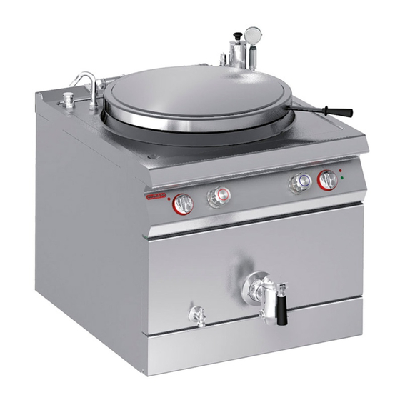
In funzione delle esigenze di utilizzo, l'apparecchia- chiatura,è stata progettata e costruita per la prepa- tura è prodotta in più versioni (vedi figura). razione e cottura di alimenti nell'ambito della ristorazione professionale. 191PI2E 191PI2EA IDM-39616400100.tif Organi principali A)Coperchio pentola B)Rubinetto acqua calda: per regolare il flusso dell'acqua. - Page 7 DATI TECNICI Vedi tabelle e "Scheda allacciamenti" in fondo al manuale. DISPOSITIVI DI SICUREZZA Anche se l'apparecchiatura è completa di tutti i di- spositivi di sicurezza, in fase di installazione e allac- ciamento essi dovranno, se necessario, essere integrati con altri in modo da rispettare le leggi vi- genti in materia.
-
Page 8: Sicurezza
ACCESSORI A RICHIESTA A richiesta l'apparecchiatura può essere corredata dei seguenti accessori. A)Colapasta B)Griglia di scarico C)Sifone di scarico D)Piedi di appoggio IDM-39616500500.tif SICUREZZA NORME PER LA SICUREZZA Il costruttore, in fase di progettazione e costru- usi impropri può recare rischi per la sicurezza e la zione, ha posto particolare attenzione agli salute delle persone e danni economici. - Page 9 Nell'uso quotidiano dell'apparecchiatura è richiesta Non lasciare oggetti o materiale infiammabile all'in- la presenza costante dell'Operatore. terno del vano o in prossimità dell'apparecchiatura. Durante il lavaggio dell'apparecchiatura non dirige- re getti d'acqua in pressione sulle parti interne dell'apparecchiatura. NORME PER LA SICUREZZA SULL'IMPATTO AMBIENTALE Ogni organizzazione ha il compito di applicare delle Sicurezza per lo smaltimento di Rifiuti di Appa- procedure per individuare e controllare l'influenza...
-
Page 10: Uso E Funzionamento
USO E FUNZIONAMENTO RACCOMANDAZIONI PER L'USO E FUNZIONAMENTO Importante L'incidenza degli infortuni derivanti cipali. Attuare solo gli usi previsti dal co- dall'uso di apparecchiature dipende da struttore manomettere nessun molti fattori che non sempre si riescono a dispositivo per ottenere prestazioni diverse prevenire e controllare. - Page 11 ACCENSIONE E SPEGNIMENTO APPARECCHIATURA Accensione 1 - Agire sull'interruttore automatico sezionatore per attivare l'allacciamento alla linea elettrica principale. 2 - Ruotare la manopola (A) in senso orario (pos. 1) in corrispondenza della temperatura desidera- ta, per attivare le resistenze di riscaldamento. La spia di rete (B) si accende.
- Page 12 RIEMPIMENTO INTERCAPEDINE Per questa operazione procedere nel modo indicato. 1 - Aprire il rubinetto (A). 2 - Svitare il tappo (B). 3 - Ruotare l'erogatore dell'acqua (C) in corrispon- denza del raccordo di riempimento (D). 4 - Aprire i rubinetti (E) per riempire l'intercapedi- 5 - Quando l'acqua incomincia ad uscire dal rubi- netto (A) chiudere i rubinetti (E) per non supe- rare il livello di riempimento ottimale.
-
Page 13: Manutenzioni
INATTIVITÀ PROLUNGATA DELL'APPARECCHIATURA Se l'apparecchiatura rimane inattiva per un lungo 3 - Cospargere con un velo d'olio alimentare le su- tempo, procedere nel modo indicato. perfici in acciaio inox. 1 - Agire sull'interruttore sezionatore dell'apparec- 4 - Eseguire tutte le operazioni di manutenzione. chiatura per disattivare l'allacciamento alla li- 5 - Ricoprire l'apparecchiatura con un involucro e nea elettrica principale. - Page 14 PULIZIA APPARECCHIATURA Se si considera che l'apparecchiatura è utilizzata Cautela - Avvertenza per la preparazione di prodotti alimentari per l'uo- Non usare prodotti che contengono sostanze mo, è necessario prestare particolare cura a tutto dannose e pericolose per la salute delle per- ciò...
-
Page 15: Guasti
INGRASSAGGIO RUBINETTO DI SCARICO Per questa operazione procedere nel modo indicato. 1 - Aprire il rubinetto di scarico (A) per vuotare la pentola e lasciarlo aperto. 2 - Allentare la vite di bloccaggio (B). 3 - Sfilare il cono (C). 4 - Controllare lo stato d'usura delle guarnizioni e, se necessario, procedere alla loro sostituzione. -
Page 16: Movimentazione E Installazione
MOVIMENTAZIONE E INSTALLAZIONE RACCOMANDAZIONI PER LA MOVIMENTAZIONE E INSTALLAZIONE Importante Eseguire la movimentazione e l'installazio- ste operazioni dovrà, se necessario, orga- ne nel rispetto delle informazioni fornite dal nizzare “piano sicurezza” costruttore e riportate direttamente sull'im- salvaguardare l'incolumità delle persone ballo, sull'apparecchiatura e nelle istruzioni direttamente coinvolte. - Page 17 INSTALLAZIONE APPARECCHIATURA Tutte le fasi di installazione devono essere conside- rate sin dalla realizzazione del progetto generale. Prima di iniziare tali fasi, oltre alla definizione della zona di installazione, chi è autorizzato ad eseguire queste operazioni dovrà, se necessario, attuare un “piano di sicurezza”...
- Page 18 LIVELLAMENTO Agire sui piedi di appoggio (A) per livellare l'appa- recchiatura. IDM-39614401600.tif MONTAGGIO APPARECCHIATURE IN BATTERIA Per montare le apparecchiature in batteria (fianco a fianco) procedere nel modo indicato. 1 - Sfilare le manopole (A). 2 - Smontare i gruppi manopole (B). 3 - Svitare le viti (C) e smontare i cruscotti (D).
- Page 19 ALLACCIAMENTO ACQUA Per effettuare l'allacciamento, collegare il tubo di rete con il tubo di attacco dell'apparecchiatura, in- terponendo un rubinetto di intercettazione (A) per interrompere, quando necessario, l'alimentazione dell'acqua. A valle di esso installare dei filtri facil- mente raggiungibili. Cautela - Avvertenza L'apparecchiatura deve essere alimentata con acqua potabile con le caratteristiche indi- cate in tabella.
-
Page 20: Regolazioni
Effettuare l'allacciamento dell'apparecchiatura alla rete di alimentazione nel modo indicato. 1 - Installare, se non è presente, un interruttore se- zionatore (A) vicino all'apparecchiatura con sganciatore magnetotermico e blocco differen- ziale. 2 - Smontare i gruppi manopole (B). 3 - Svitare le viti (C) e smontare il cruscotto (D). 4 - Collegare l'interruttore sezionatore (A) alla morsettiera (E) dell'apparecchiatura come indi- cato in figura e nello schema elettrico in fondo... -
Page 21: Sostituzione Parti
REGOLAZIONE BILANCIAMENTO COPERCHIO Per questa operazione procedere nel modo indica- 1 - Inserire la chiave (A) nell'esagono (B). 2 - Tenere saldamente la chiave (A) e, contempo- raneamente, svitare le viti di bloccaggio (C). 3 - Ruotare la chiave (A) in senso orario per cari- care la molla o in senso antiorario per scaricar- 4 - Ottenuto il giusto bilanciamento, avvitare le viti (C) senza stringerle. - Page 23 PENTOLA INDIRETTA “ELETTRICA” ELECTRIC JACKETED BOILING PAN 191PI2E ”ELEKTROBEHEIZTER” DOPPELWANDIGER KOCHKESSEL 191PI2EA MARMITE CHAUFFE INDIRECTE "ÉLECTRIQUE" MARMITA INDIRECTA “ELÉCTRICA” MANUALE D’USO E INSTALLAZIONE USE AND INSTALLATION MANUAL BEDIEN- UND INSTALLATIONSHANDBUCH MANUEL D’UTILISATION ET D’INSTALLATION MANUAL DE USO E INSTALACIÓN Italiano...
- Page 25 CONTENTS ref. chapters page 1 GENERAL INFORMATION ..........2 2 TECHNICAL INFORMATION ..........4 3 SAFETY ................6 PART 4 USE AND OPERATION ............. 8 5 SERVICING ..............11 6 FAULT ................13 7 HANDLING AND INSTALLATION ........14 8 ADJUSTMENTS ............... 18 PART 9 REPLACING PARTS ............
-
Page 26: General Information
GENERAL INFORMATION INFORMATION FOR THE READER To find the specific topics of interest to you quickly, 2nd part: contains all the information neces- refer to the index at the start of the manual. sary for special categories of reader, i.e. all This manual is subdivided into two parts. - Page 27 IDENTIFICATION OF CONSTRUCTOR AND APPLIANCE The nameplate shown here is fitted directly to the G)Protection rating appliance. It contains references and all essential H)Country of destination information for operating safety. L) Voltage (V) A)Appliance model M)Absorption (A) B)Type of customisation N)Frequency (Hz) C)Constructor identification P)Rated power (kW)
-
Page 28: Technical Information
The appliance is produced in several versions to now on as the appliance, is designed and construct- meet varying user requirements (see diagram). ed for preparing and cooking foods in the profes- sional catering sector. 191PI2E 191PI2EA IDM-39616400100.tif Main Parts A)Pan lid... - Page 29 TECHNICAL DATA See tables and "Connection chart" at the back of the manual. SAFETY DEVICES Although the appliance is complete with all safety devices, during installation and connection addi- tional devices must be added if necessary to com- ply with the relevant legal requirements. A)Safety thermostat: cuts off the electricity supply in case of overheating.
-
Page 30: Safety
OPTIONAL ACCESSORIES The appliance can be equipped with the following accessories on request. A)Pasta basket B)Drain grid C)Drain siphon D)Feet IDM-39616500500.tif SAFETY SAFETY REGULATIONS During design and construction, the construc- All servicing operations requiring specific technical tor has paid special attention to factors which knowledge or skills must only be carried out by may cause risks to the health and safety of the qualified staff with recognised experience in the... - Page 31 During routine use of the appliance, the Operator's Do not leave flammable objects or materials inside constant presence is required. or close to the appliance. When washing the appliance do not point pressu- rised water jets at internal parts. ENVIRONMENTAL IMPACT SAFETY REGULATIONS Every organisation is obliged to apply procedures to The Safe Disposal of Waste from Electrical and identify and monitor the effects of its operations...
-
Page 32: Use And Operation
USE AND OPERATION RECOMMENDATIONS FOR USE Important The rate of accidents deriving from the use and the main functions. Use only as intend- of appliances depends on many factors ed by the constructor and never tamper which cannot always be foreseen and con- with any device to obtain performance lev- trolled. - Page 33 SWITCHING THE APPLIANCE ON AND OFF Lighting 1 - Turn on the appliance's circuit breaker to con- nect it to the electrical mains. 2 - Turn the knob (A) clockwise (pos. 1) to the tem- perature required to turn on the heating ele- ments.
- Page 34 FILLING THE JACKET To carry out this operation, proceed as follows. 1 - Turn on the tap (A). 2 - Unscrew the cap (B). 3 - Turn the water spout (C) towards the filler con- nection (D). 4 - Turn on the taps (E) to fill the jacket. 5 - When water starts to flow from the tap (A), turn off the taps (E) to avoid overfilling.
-
Page 35: Servicing
LENGTHY DOWNTIMES OF APPLIANCE If the appliance is to be out of use for a lengthy pe- 3 - Spread a film of edible oil over the stainless riod, proceed as follows. steel surfaces. 1 - Cut off the mains electricity supply using the ap- 4 - Carry out all the servicing procedures. - Page 36 CLEANING INSTRUCTIONS Since the appliance is used for preparing foods for – After use, clean the accessories with a suitable human consumption, special care must be paid to grease-remover product. If possible, wash in the everything relating to hygiene, and the appliance dishwasher.
-
Page 37: Fault
GREASING THE DRAIN TAP To carry out this operation, proceed as follows. 1 - Turn on the drain tap (A) to empty the pan, and leave it open. 2 - Undo the locking screw (B). 3 - Pull off the cone (C). 4 - Check the seals for wear and replace them if necessary. -
Page 38: Handling And Installation
HANDLING AND INSTALLATION RECOMMENDATIONS FOR HANDLING AND INSTALLATION Important When handling and installing the appliance use. If necessary, the person authorised to comply with the information provided by carry out these operations must organise a the constructor directly on the packaging, "safety plan"... - Page 39 INSTALLATION OF THE APPLIANCE All installation stages must be considered right from production of the general layout. Before starting these stages, as well as deciding the place of instal- lation, if necessary, the person authorised to carry out these operations must organise a "safety plan" to protect the people directly involved, and he must also ensure strict compliance with all legal require- ments, especially those relating to mobile work-...
- Page 40 LEVELLING Adjust the floor-mounted feet (A) to level the appli- ance. IDM-39614401600.tif ASSEMBLY APPLIANCES IN BANKS To assemble appliances in banks (side by side) proceed as described below. 1 - Pull off the knob (A). 2 - Remove the knob unit (B). 3 - Undo the screws (C) and remove the control panels (D).
- Page 41 WATER CONNECTION To make the connection, connect the mains line to the appliance's connection pipe, fitting a shut-off tap (A), to allow the water supply to be cut off when necessary. Easily accessible filters must be fitted downstream of the tap. Caution - warning The appliance must be supplied with drinking water having the characteristics shown in the...
-
Page 42: Adjustments
Connect the appliance to the mains electricity sup- ply as follows. 1 - If not already present, install a circuit-breaker (A) with overload cutout and differential safety breaker close to the appliance. 2 - Remove the knob unit (B). 3 - Undo the screws (C) and remove the control panel (D). -
Page 43: Replacing Parts
ADJUSTING THE LID COUNTER-BALANCING To carry out this operation, proceed as follows. 1 - Fit the spanner (A) onto the hexagon (B). 2 - Keep a firm grip on the spanner (A) and undo the locking screws (C). 3 - Turn the spanner (A) clockwise to load the spring or anti-clockwise to release it. - Page 45 INHALTSVERZEICHNIS Ref. Kapitel Seite 1 ALLGEMEINES ..............2 2 TECHNISCHE INFORMATIONEN ........4 3 SICHERHEIT ..............6 1. TEIL 4 GEBRAUCH UND BETRIEB ..........8 5 WARTUNG ............... 11 6 DEFEKTE ................. 13 7 HANDHABUNG UND INSTALLATION ......14 8 EINSTELLUNGEN ............18 2.
-
Page 46: Allgemeines
ALLGEMEINES INFORMATIONEN FÜR DEN LESER Konsultieren Sie das Sachregister, das am Anfang 2. Teil: Diese Informationen wenden sich an des Handbuchs zu finden ist, um leichter unter be- eine bestimmte Zielgruppe. Sie sind für erfahre- stimmten Themen von besonderem Interesse ne Bediener bestimmt, die für Handhabung, nachschlagen zu können. - Page 47 TYPENSCHILD FÜR HERSTELLER UND GERÄT Das abgebildete Typenschild wird direkt auf dem G)Schutzart Gerät aufgebracht. Es enthält sämtliche Angaben H)Bestimmungsland und Hinweise, die für den sicheren Betrieb unerläs- L) Spannung (V) slich sind. M)Stromaufnahme (A) A)Gerätemodell N)Frequenz (Hz) B)Art der Anpassung P)Angabe der Leistung (Kw) C)Angabe des Herstellers Q)Abnahmespannungsanzeige...
-
Page 48: Technische Informationen
Der doppelwandige Kochkessel, der im Folgenden Das Gerät wird bedarfsabhängig in verschiedenen als Gerät bezeichnet wird, wurde zum Zubereiten Versionen hergestellt (siehe Abbildung). und Garen von Speisen in Restaurantbetrieben projektiert und konstruiert. 191PI2E 191PI2EA IDM-39616400100.tif Hauptorgane A)Deckel des Kochkessels B)Warmwasserhahn: zum Regulieren der Wasser-... - Page 49 TECHNISCHE DATEN Siehe Tabellen und „Anschlussschema" am Ende des Handbuchs. SICHERHEITSVORRICHTUNGEN Das Gerät wird zwar mit sämtlichen planmäßigen Sicherheitsvorrichtungen geliefert, es kann jedoch notwendig sein, während Installation und An- schluss ggf. weitere ergänzende Maßnahmen zu ergreifen, um den Anforderungen der einschlägi- gen geltenden Gesetze zu entsprechen.
-
Page 50: Sicherheit
OPTIONALES ZUBEHÖR Auf Wunsch kann das Gerät mit folgenden Zube- hörteilen ausgestattet werden. A)Abtropfsieb B)Abflussgitter C)Siphon D)Stützfüße IDM-39616500500.tif SICHERHEIT SICHERHEITSVORSCHRIFTEN Der Hersteller hat bei Entwicklung und Ferti- missbräuchliche Einsatz des Geräts kann schwer- gung dieses Produkts besondere Sorgfalt auf wiegende Gefahren für Sicherheit und Gesundheit Aspekte verwendet, die eine Gefahr für die Si- von Personen und finanzielle Verluste hervorrufen. - Page 51 Beim täglichen Gebrauch des Geräts ist die ständi- Keine entzündlichen Gegenstände oder Materialien ge Anwesenheit des Bedienungspersonals erfor- im Schrank oder in der Nähe des Geräts aufbewah- derlich. ren. Beim Waschen des Geräts den Wasserstrahl nicht direkt auf die inneren Teile des Geräts richten. SICHERHEITSVORSCHRIFTEN IN HINBLICK AUF DIE UMWELTBELASTUNG Alle Betriebe müssen den Einfluss, den ihre Tätig-...
-
Page 52: Gebrauch Und Betrieb
GEBRAUCH UND BETRIEB EMPFEHLUNGEN FÜR DEN GEBRAUCH Wichtig Das Auftreten von Unfällen bei der Verwen- Sie sich auf die vom Hersteller vorgesehenen dung von Geräten hängt von vielen Faktoren Verwendungszwecke, ohne Änderungen an ab, die nicht immer zu vermeiden und zu steu- den Vorrichtungen vorzunehmen, um nicht ern sind. - Page 53 EIN- UND AUSSCHALTEN DES GERÄTS Zündung 1 - Mit dem Trennschalter den Anschluss an das Stromnetz herstellen. 2 - Den Schalter (A) durch Drehung im Uhrzeiger- sinn (Pos. 1) auf die gewünschte Temperatur stellen, um die Heizwiderstände einzuschalten. Die Kontrollleuchte Gaszufuhr (B) schaltet sich ein.
- Page 54 FÜLLEN DES HOHLRAUMS Für diesen Vorgang in der angegebenen Weise verfahren. 1 - Den Hahn (A) öffnen. 2 - Den Verschluss (B) ausschrauben. 3 - Das Wasserauslaufrohr (C) auf Höhe des Ein- füllanschlusses (D) drehen. 4 - Die Hähne (E) öffnen, um den Hohlraum zu fül- len.
-
Page 55: Wartung
LÄNGERER STILLSTAND DES GERÄTS Verfahren Sie folgendermaßen, falls das Gerät län- 3 - Tragen Sie eine hauchdünne Schicht Lebens- gere Zeit nicht eingesetzt werden soll: mittelöl auf die Edelstahlflächen auf. 1 - Das Gerät mit seinem Trennschalter vom 4 - Führen Sie sämtliche Wartungsarbeiten aus. Hauptstromnetz trennen. - Page 56 REINIGUNG DES GERÄTS Da das Gerät zur Zubereitung von Speisen für den Vorsicht - Achtung Menschen eingesetzt wird, ist besondere Sorgfalt Verwenden Sie keine Produkte, die Stoffe ent- auf die Hygiene geboten. Das Gerät und dessen halten, welche für die menschliche Gesund- näheres Umfeld müssen konstant sauber gehalten werden.
-
Page 57: Defekte
FETTSCHMIEREN DES ABLASSHAHNS Für diesen Vorgang in der angegebenen Weise verfahren. 1 - Den Ablasshahn (A) öffnen und den Kochkes- sel entleeren; den Hahn geöffnet lassen. 2 - Die Klemmschraube (B) lockern. 3 - Ziehen Sie den Kegel (C) heraus. 4 - Die Dichtungen auf Verschleiß... -
Page 58: Handhabung Und Installation
HANDHABUNG UND INSTALLATION EMPFEHLUNGEN FÜR DIE INSTALLATION UND HANDHABUNG Wichtig Beachten Sie die Hinweise des Herstellers, nen autorisierte Person wird bei Bedarf die direkt auf der Verpackung, auf dem Ge- einen „Sicherheitsplan" aufstellen müssen, rät selbst oder in der Gebrauchsanweisung um die Unversehrtheit der direkt an dem zu finden sind, wenn Sie das Gerät handha- Vorgang beteiligten Personen zu gewähr-... - Page 59 INSTALLATION DES GERÄTS Es müssen sämtliche Phasen der Installation, schon von der Umsetzung des allgemeinen Pro- jekts an, berücksichtigt werden. Die für diese Ope- rationen autorisierte Person wird vor Einleitung dieser Phasen den Installationsstandort bestimmen und bei Bedarf einen „Sicherheitsplan" aufstellen, um die Unversehrtheit der direkt am Vorgang betei- ligten Personen zu gewährleisten und die gesetzli- chen Bestimmungen zu befolgen.
- Page 60 NIVELLIEREN Regulieren Sie die Füße (A), um das Gerät wasser- waagengerecht aufzustellen. IDM-39614401600.tif MONTAGE BEI REIHENAUFSTELLUNG Verfahren Sie folgendermaßen, um Geräte (neben- einander) in einer Reihe aufzustellen. 1 - Den Schalter (A) abziehen. 2 - Die Schalterbaugruppe (B) ausbauen. 3 - Die Schrauben (C) ausschrauben und die Blen- den (D) ausbauen.
- Page 61 WASSERANSCHLUSS Schließen Sie den Zufuhrschlauch der Wasserlei- tung an das Anschlussrohr des Gerätes an. Bringen Sie hierbei einen Absperrhahn (A) an, um die Was- serzufuhr bei Bedarf absperren zu können. Hinter diesen Absperrhahn müssen leicht zugängliche Fil- ter eingebaut werden. Vorsicht - Achtung Das Gerät muss mit Trinkwasser gespeist werden, dass die in der Tabelle angegebenen...
-
Page 62: Einstellungen
Den Anschluss des Geräts an das Stromnetz in der angegebenen Weise ausführen. 1 - Falls nicht schon vorhanden, einen Trennschalter (A) mit thermomagnetischem Auslöser und FI- Block in der Nähe des Geräts installieren. 2 - Die Schalterbaugruppe (B) ausbauen. 3 - Drehen Sie die Schrauben (C) heraus und mon- tieren Sie die Blende (D) ab. -
Page 63: Austausch Von Bauteile
EINSTELLUNG DER AUSWUCHTUNG DES DECKELS Für diesen Vorgang in der angegebenen Weise verfahren. 1 - Den Schlüssel (A) in den Sechskant (B) einset- zen. 2 - Den Schlüssel (A) gut festhalten und gleichzei- tig die Feststellschrauben (C) ausschrauben. 3 - Den Schlüssel (A) zum Spannen der Feder im Uhrzeigersinn, und zum Entspannen der Feder entgegen dem Uhrzeigersinn drehen. - Page 65 INDEX réf. chapitres page 1 INFORMATIONS GENERALES ......... 2 2 INFORMATIONS TECHNIQUES ........4 3 SÉCURITÉ ................. 6 PARTIE 4 UTILISATION ET FONCTIONNEMENT ......8 5 ENTRETIEN ..............11 6 PANNES ................13 7 MANUTENTION ET INSTALLATION ....... 14 8 RÉGLAGES ..............18 PARTIE 9 REMPLACEMENT DE PIÈCES ........
- Page 66 INFORMATIONS GENERALES INFORMATIONS POUR LE LECTEUR Pour retrouver facilement les sujets qui vous inté- 2e partie: elle contient toutes les informa- ressent, consulter l’index analytique au début du tions nécessaires aux destinataires homogè- manuel. nes, c'est-à-dire tous les opérateurs experts Ce manuel est divisé...
- Page 67 IDENTIFICATION DU FABRICANT ET DE L’APPAREIL La plaque d’identification représentée, est appli- G)Degré de protection quée directement sur l'appareil. Elle reporte les ré- H)Pays de destination férences et les indications indispensables à la L) Tension (V) sécurité. M)Absorption (A) A)Modèle de l’appareil N)Fréquence (Hz) B)Type de personnalisation P)Puissance déclarée (kW)
- Page 68 En fonction des exigences d'utilisation, l'appareil maintenant appareil, a été conçue et fabriquée pour est réalisé en plusieurs versions (voir figure). la préparation et la cuisson d'aliments dans le do- maine de la restauration professionnelle. 191PI2E 191PI2EA IDM-39616400100.tif Organes principaux A)Couvercle de la marmite B)Robinet d'eau chaude: pour régler le flux de l'eau...
- Page 69 DONNÉES TECHNIQUES Voir tableaux et « Fiche des raccordements » à la fin du manuel. DISPOSITIFS DE SÉCURITÉ Même si l’appareil est complet de tous les disposi- tifs de sécurité, lors de l’installation et du raccorde- ment, ils devront, si nécessaire, être intégrés avec d’autres pour respecter les lois en vigueur.
- Page 70 ACCESSOIRES SUR DEMANDE Sur demande l'appareil peut être équipé des acces- soires suivants. A)Passoire B)Grille de vidange C)Siphon de vidange D)Pieds d’appui IDM-39616500500.tif SÉCURITÉ NORMES DE SÉCURITÉ Le fabricant, lors de la conception et de la fabri- Tous les entretiens qui demandent une compéten- cation, a fait très attention aux aspects qui peu- ce technique précise ou des capacités particulières vent provoquer des risques à...
- Page 71 Un opérateur doit être constamment présent pen- Ne pas laisser d’objets ou de matériau inflammable dant l’utilisation quotidienne de l’appareil. à l’intérieur du compartiment ou à proximité de l’ap- pareil. Pendant le lavage de l’appareil ne pas diriger de jets d’eau sous pression sur les pièces intérieures. NORMES POUR LA SÉCURITÉ...
- Page 72 UTILISATION ET FONCTIONNEMENT RECOMMANDATIONS POUR L'UTILISATION Important L'incidence des accidents dérivant de l'uti- les. Utiliser seulement comme prévu par le lisation d'appareils dépend de beaucoup de fabricant et ne modifier aucun dispositif facteurs que l'on ne peut pas toujours pré- pour obtenir des performances différentes venir et contrôler.
- Page 73 ALLUMAGE ET EXTINCTION DE L’APPAREIL Allumage 1 - Agir sur l'interrupteur sectionneur automatique pour activer le branchement à la ligne électri- que principale. 2 - Tourner la manette (A) en sens horaire (pos. 1) en correspondance de la température désirée pour activer les résistances de chauffe.
- Page 74 REMPLISSAGE INTER PAROIS Pour cette opération, procéder comme suit. 1 - Ouvrir le robinet (A). 2 - Dévisser le bouchon (B) 3 - Tourner l'érogateur de l'eau (C) en correspon- dance du raccord de remplissage (D). 4 - Ouvrir les robinets (E) pour remplir l’inter parois. 5 - Lorsque l’eau commence à...
- Page 75 INUTILISATION PROLONGÉE DE L’APPAREIL Si l'appareil reste inactif pendant longtemps, procé- 3 - Étaler un voile d’huile alimentaire sur les surfa- der comme suit. ces en acier inox. 1 - Agir sur l'interrupteur sectionneur de l’appareil 4 - Exécuter toutes les opérations d’entretien. pour désactiver le branchement à...
- Page 76 NETTOYAGE DE L’APPAREIL Étant donné que l'appareil est utilisé pour la prépa- – Nettoyer les accessoires après leur utilisation ration de produits alimentaires pour l'homme, il faut avec un dégraissant approprié. Le lavage en faire attention à tout ce qui concerne l'hygiène; l'ap- lave-vaisselle est conseillé.
- Page 77 GRAISSAGE DU ROBINET DE VIDANGE Pour cette opération, procéder comme suit. 1 - Ouvrir le robinet de vidange (A) pour vider la marmite et le laisser ouvert. 2 - Desserrer la vis de blocage (B). 3 - Extraire le cône (C). 4 - Contrôler l'état d’usure des joints et, si néces- saire, les remplacer.
- Page 78 MANUTENTION ET INSTALLATION RECOMMANDATIONS POUR LA MANUTENTION ET L’INSTALLATION Important Effectuer la manutention et l’installation en effectuer ces opérations devra, si nécessai- respectant les informations fournies par le re, organiser un « plan de sécurité » pour fabricant, reportées directement sur l’em- sauvegarder la sécurité...
- Page 79 MISE EN PLACE DE L’APPAREIL Toutes les phases de mise en place doivent être prises en considération, dès la réalisation du projet général. Avant de commencer ces phases, outre la définition de la zone de mise en place, celui qui est autorisé...
- Page 80 MISE À NIVEAU Agir sur les pieds d’appui (A) pour mettre de niveau l’appareil. IDM-39614401600.tif MONTAGE DES APPAREILS EN BATTERIE Pour monter les appareils en batterie (les uns à côté des autres), procéder comme suit. 1 - Enlever la manette (A). 2 - Démonter le groupe manette (B).
- Page 81 RACCORDEMENT DE L'EAU Pour effectuer le raccordement, raccorder le tuyau de réseau et le tuyau de raccord de l’appareil, en in- terposant un robinet d’arrêt (A), pour interrompre, si nécessaire, l’alimentation de l’eau. En aval de celui- ci, installer des filtres facilement accessibles. Attention L’appareil doit être alimenté...
- Page 82 Effectuer le branchement de l'appareil au réseau électrique d'alimentation comme suit. 1 - Installer, s’il n’est pas présent, un interrupteur sectionneur (A) près de l’appareil avec déclen- cheur magnétothermique et bloc différentiel. 2 - Démonter le groupe manette (B). 3 - Dévisser les vis (C) et démonter le tableau de commandes (D).
- Page 83 RÉGLAGE DE L'ÉQUILIBRE DU COUVERCLE Pour cette opération, procéder comme suit. 1 - Introduire la clé (A) dans l'hexagone (B). 2 - Tenir solidement la clé (A) et, simultanément, dévisser les vis de blocage (C). 3 - Tourner la clé (A) en sens horaire pour charger le ressort et en sens anti-horaire pour le dé- charger.
- Page 85 ÍNDICE ref. capítulos pág 1 INFORMACIONES DE CARÁCTER GENERAL ....2 2 INFORMACIONES DE CARÁCTER TÉCNICO ....4 3 SEGURIDAD ..............6 PARTE 4 USO Y FUNCIONAMIENTO ..........8 5 MANTENIMIENTO ............11 6 AVERÍAS ................13 7 DESPLAZAMIENTO E INSTALACIÓN ......14 8 REGULACIONES .............
-
Page 86: Informaciones De Carácter General
INFORMACIONES DE CARÁCTER GENERAL INFORMACIONES PREVIAS Para ubicar fácilmente los temas específicos de in- 2a parte: contiene todas las informaciones terés, consúltese el índice analítico que se encuen- necesarias para destinatarios homogéneos, tra al inicio del manual. esto es, todos los operadores expertos y au- Este manual comprende dos partes. - Page 87 IDENTIFICACIÓN FABRICANTE Y EQUIPO La placa de identificación fijada directamente en el G)Grado de protección equipo reproduce todas las referencias e indicacio- H)País de destino nes indispensables para la seguridad de servicio. L) Tensión (V) A)Modelo del aparato M)Consumo (A) B)Tipo de personalización N)Frecuencia (Hz) C)Identificación fabricante...
-
Page 88: Informaciones De Carácter Técnico
(véa- para la preparación y la cocción de alimentos en el se figura). sector de la restauración profesional. 191PI2E 191PI2EA IDM-39616400100.tif Órganos principales A)Tapa de la marmita... - Page 89 DATOS TÉCNICOS Véase tablas y "Ficha de enlaces" al final del ma- nual. DISPOSITIVOS DE SEGURIDAD Aunque el equipo cuente con todos los dispositivos de seguridad, en los casos en que así lo determi- nen las leyes vigentes en materia, se deberá com- plementar con otros dispositivos en las fases de instalación y enlace.
-
Page 90: Seguridad
ACCESORIOS BAJO PEDIDO Bajo pedido, el equipo puede ser suministrado con los accesorios que a continuación se indican. A)Colador B)Rejilla de descarga C)Sifón de desagüe D)Pies de apoyo IDM-39616500500.tif SEGURIDAD NORMAS DE SEGURIDAD Durante las fases de diseño y producción el fa- sar riesgos en cuanto a seguridad y salud de las bricante ha prestado especial atención a los fac- personas, además de daños económicos. - Page 91 Durante el uso cotidiano del aparato se requiere la No dejar objetos o material inflamable en el interior presencia constante del operador. del compartimiento ni en proximidad del aparato. Durante el lavado del aparato no dirigir chorros de agua a presión hacia sus partes internas. NORMAS DE SEGURIDAD RELATIVAS AL IMPACTO AMBIENTAL Toda organización tiene el deber de aplicar proce- Eliminación segura de los residuos de aparatos...
-
Page 92: Uso Y Funcionamiento
USO Y FUNCIONAMIENTO RECOMENDACIONES DE USO Importante El porcentaje de accidentes derivados del pias de los usos previstos por el fabricante. uso de equipos depende de muchos facto- No alterar los equipos con el fin de obtener res que no siempre se logran prevenir y prestaciones diferentes de las previstas. - Page 93 ENCENDIDO Y APAGADO DEL APARATO Encendido 1 - Operar con el interruptor automático aislador para activar la conexión a la línea eléctrica prin- cipal. 2 - Girar el mando (A) en sentido horario (pos. 1) para situarlo en correspondencia con la tempe- ratura requerida;...
- Page 94 LLENADO CÁMARA DE AIRE Para efectuar esta operación, aplicar las siguientes instrucciones. 1 - Abrir el grifo (A). 2 - Desenroscar el tapón (B). 3 - Girar el grifo del agua (C) en correspondencia con el racor de llenado (D). 4 - Abrir los grifos (E) para llenar la cámara de aire.
-
Page 95: Mantenimiento
PERÍODO PROLONGADO DE INACTIVIDAD DEL EQUIPO En caso de que el equipo deba permanecer inacti- 3 - Esparcir sobre las superficies de acero inoxidable vo durante un período prolongado de tiempo, se una capa delgada de aceite comestible. deberán efectuar las siguientes operaciones. 4 - Efectuar todas las operaciones de manteni- 1 - Con el interruptor aislador del aparato desacti- miento. - Page 96 LIMPIEZA APARATO Atendida la circunstancia de que el equipo es utili- vecinas. zado para la preparación de productos alimenticios – Limpiar los accesorios después del uso utilizan- para el consumo humano, es necesario prestar es- do un desengrasante adecuado. Se aconseja pecial atención a todo lo referente a la higiene, efectuar el lavado en lavavajillas.
-
Page 97: Averías
LUBRICACIÓN DEL GRIFO DE DESCARGA Para efectuar esta operación, aplicar las siguientes instrucciones. 1 - Abrir el grifo de descarga (A) para vaciar la marmita y déjelo abierto. 2 - Aflojar el tornillo de fijación (B). 3 - Extraer el cono (C). 4 - Controlar el nivel de desgaste de las juntas y, si es necesario, cambiarlas. -
Page 98: Desplazamiento E Instalación
DESPLAZAMIENTO E INSTALACIÓN RECOMENDACIONES PARA EL DESPLAZAMIENTO Y LA INSTALACIÓN Importante Efectuar el desplazamiento e instalación rizada para efectuar estas operaciones de- respetando las indicaciones proporciona- berá, si fuera necesario, organizar un "plan das por el fabricante, reproducidas directa- de seguridad", a fin de salvaguardar la in- mente sobre el embalaje, en el equipo y en columidad de las personas directamente las instrucciones de uso. - Page 99 INSTALACIÓN DEL EQUIPO Durante la realización del proyecto general, deben ser consideradas todas las fases de la instalación. Antes de comenzar dichas fases, además de esta- blecer la zona de instalación, la persona autorizada a efectuar estas operaciones deberá, si fuera nece- sario, aplicar un "plan de seguridad"...
- Page 100 NIVELACIÓN Operar con las patas de apoyo (A) para nivelar el equipo. IDM-39614401600.tif MONTAJE DE EQUIPOS EN BATERÍA Para montar los equipos en batería (uno al lado del otro) aplicar las siguientes instrucciones. 1 - Retirar el mando (A). 2 - Desmontar la unidad del mando (B). 3 - Desenroscar los tornillos (C) y desmontar los pa- neles de mando (D).
- Page 101 ENLACE AGUA Para efectuar el enlace, conectar el tubo de red con el tubo de conexión del equipo, instalando un grifo de interceptación (A) a fin de poder interrumpir, cuando sea necesario, la alimentación del agua. En posición sucesiva al grifo se deben instalar filtros de fácil acceso.
-
Page 102: Regulaciones
Conectar el aparato a la red eléctrica de alimenta- ción respetando las siguientes instrucciones. 1 - En caso de no estar presente, instalar un inte- rruptor seccionador (A) en proximidad del apa- rato con desconectador magnetotérmico y bloqueo diferencial. 2 - Desmontar la unidad del mando (B). 3 - Desenroscar los tornillos (C) y desmontar el ta- blero de instrumentos (D). -
Page 103: Sostitución De Piezas
REGULACIÓN BALANCEO TAPA Para efectuar esta operación, aplicar las siguientes instrucciones. 1 - Insertar la llave (A) en el hexágono (B). 2 - Sostener firmemente la llave (A) y, de modo simultáneo, desenroscar los tornillos de fija- ción (C). 3 - Girar la llave (A) en sentido horario para cargar el resorte o en sentido antihorario para descar- garlo. -
Page 104: Anexos
N. 1 (150 lt.) 14 kW 400V3~ 50-60Hz 20,2 A 191PI2E N. 1 (150 lt.) 14 kW 230V3~ 50-60Hz 35 A SCHEDA ALLACCIAMENTI (191PI2E) - CONNECTION CARD (191PI2E) - ANSCHLUSSSCHEMA (191PI2E) - FICHE DES RACCORDEMENTS (191PI2E) FICHA DE ENLACES (191PI2E) IDM-39616401500.tif... - Page 105 Dati elettrici Electrical data - Daten zur Elektrik Modello Vasca Potenza Données électriques - Datos eléctricos Model - Modelle Well - Becken Power - Leistung Tensione Frequenza Corrente Modèle - Modelo Cuve - Cuba Puissance - Potencia Voltage - Spannung Frequency - Frequenz Current - Strom Tension - Tensión...
- Page 106 SCHEMA ELETTRICO (191PI2E-191PI2EA 400V/3) - ELECTRICAL SYSTEM DIAGRAM (191PI2E-191PI2EA 400V/3) - ELEKTRISCHER SCHALTPLAN (191PI2E-191PI2EA 400V/3) - SCHÉMA ÉLECTRIQUE (191PI2E-191PI2EA 400V/3) - ESQUEMA ELÉCTRICO (191PI2E-191PI2EA 400V/3) Collegamento resistenze Heating elements connection Anschluss der Heizkörper Branchement des résistances Conexión resistencias IDM-39616401700.tif 1) Morsettiera - Terminal board - Klemmenbrett - Plaque à bornes - Regleta de droite - Resistencia derecha conexión...
- Page 107 SCHEMA ELETTRICO (191PI2E - 191PI2EA 230V/3) - ELECTRICAL SYSTEM DIAGRAM (191PI2E - 191PI2EA 230V/3) - ELEKTRISCHER SCHALTPLAN (191PI2E - 191PI2EA 230V/3) - SCHÉMA ÉLECTRIQUE (191PI2E - 191PI2EA 230V/3) - ESQUEMA ELÉCTRICO (191PI2E - 191PI2EA 230V/3) Collegamento resistenze Heating elements connection Anschluss der Heizkörper...
Need help?
Do you have a question about the 191PI2E and is the answer not in the manual?
Questions and answers