
Related Manuals for Teledyne Princeton Instruments IsoPlane 81


Summary of Contents for Teledyne Princeton Instruments IsoPlane 81
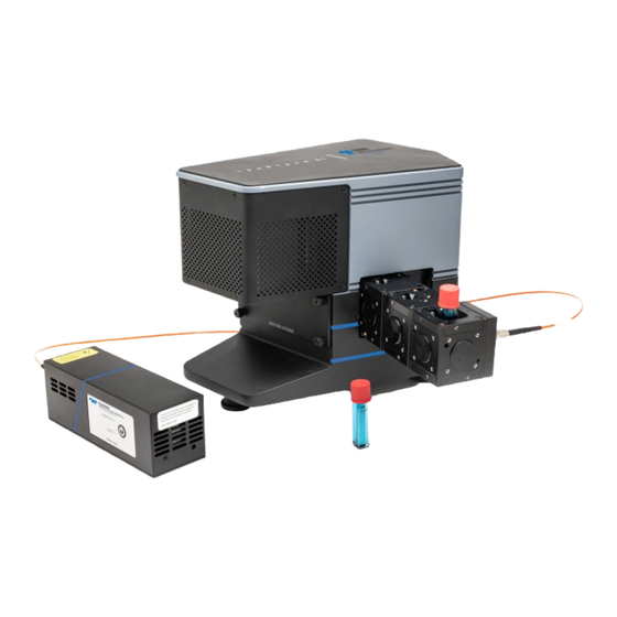
- Page 1 ® IsoPlane 81 Imaging Spectrometer System Manual 4411-0167 Issue 1 December 21, 2020 www.princetoninstruments.com...
- Page 2 Trenton, NJ 08619 TEL: 800-874-9789 / 609-587-9797 FAX: 609-587-1970 All rights reserved. No part of this publication may be reproduced by any means without the written permission of Teledyne Princeton Instruments. Printed in the United States of America. IntelliCal, IsoPlane, LightField, and eXcelon are registered trademarks of Teledyne Digital Imaging US, Inc.
-
Page 3: Table Of Contents
Table of Contents Chapter 1: About this Manual..........5 Intended Audience . - Page 4 ® IsoPlane 81 Imaging Spectrometer System Manual Issue 1 Grating Carrier Replacement Procedure ........41 Grating Carrier Alignment .
-
Page 5: Chapter 1: About This Manual
IsoPlane 81 Imaging Spectrometer System Data Sheet Teledyne Princeton Instruments maintains updated documentation and user manuals on their FTP site. Visit the Teledyne Princeton Instruments FTP Site to verify that the most recent user manual is available and being referenced: ftp://ftp.princetoninstruments.com/Public/Manuals/Princeton... -
Page 6: Document Organization
IsoPlane 81 Imaging Spectrometer System, as well as options that are available for purchase from Teledyne Princeton Instruments. • Chapter 3, Installation of LightField for the IsoPlane 81 This chapter provides information about the installation of Teledyne Princeton ® Instruments LightField data acquisition software. -
Page 7: Safety Information
Chapter 1 About this Manual Safety Information This section provides information about all Laser Warning symbols, as well as other safety-related symbols used within this manual. CAUTION! Use of controls or adjustments or performance of procedures other than those specified herein may result in hazardous radiation exposure. -
Page 8: Laser Warning Symbols
® IsoPlane 81 Imaging Spectrometer System Manual Issue 1 1.4.2 Laser Warning Symbols This section illustrates typical Laser Warning Labels related to the operation of the IsoPlane 81 Imaging Spectrometer System and the IsoPlane 81 Diode Laser Source. Figure 1-1: Typical Laser Aperture Label Figure 1-2: Typical Laser Warning Label... -
Page 9: Isoplane 81 Safety Information
WARNINGS! If the IsoPlane 81 system is used in a manner not specified by Teledyne Princeton Instruments, the protection provided by the equipment may be impaired. 2. If the equipment or the wall outlet is damaged, the protective grounding could be disconnected. - Page 10 ® IsoPlane 81 Imaging Spectrometer System Manual Issue 1 This page is intentionally blank.
-
Page 11: Isoplane 81 System
Chapter 2: IsoPlane 81 System This chapter provides an introduction to, and overview information about, Teledyne Princeton Instruments’ IsoPlane 81 Imaging Spectrometer System. The IsoPlane 81 is an integrated 80.8 mm focal length imaging spectrometer with a built-in 256 x 1024 (row x column) TEC-cooled back-illuminated CCD detector and a motorized single-turret grating drive. -
Page 12: Experiment Interface Panel
® IsoPlane 81 Imaging Spectrometer System Manual Issue 1 • Diffraction Grating; Each IsoPlane 81 is shipped with a user-replaceable diffraction grating already installed in the instrument. Additional gratings may be purchased separately. • Focusing CUBE; A Focusing CUBE is shipped with each IsoPlane 81. This CUBE houses an f/4 double achromatic lens with a clear aperture diameter of 7.5 mm. -
Page 13: Isoplane 81 System Maintenance
Chapter 2 IsoPlane 81 System Figure 2-3: IsoPlane 81 Power and Data Interface Panel Table 2-2 provides information about the power and data interface ports. Table 2-2: Power and Data Interface Panel Port Description User Input/Output General purpose input/output port. Output Trigger A, B Fully programmable output triggers using the integrated Timing Generator. -
Page 14: Repairs
2.3.2 Repairs Because the IsoPlane 81 system contains no user-serviceable parts, repairs must be performed by Teledyne Princeton Instruments. Should the system need repair, contact Teledyne Princeton Instruments customer support for instructions. Refer to Contact Information on page 60 for complete information. - Page 15 Chapter 2 IsoPlane 81 System Table 2-3: Available IsoPlane 81 System Accessories (Sheet 2 of 5) Accessory Description Part Number IsoPlane 81 Slit Interchangeable input slit; ISO81-SLIT-HK μ Precision laser-cut slit, 25 m pinhole for kinetic mode. IsoPlane 81 Interchangeable by user; ISO81-GRT- Aluminum-Coated Ruled 3600 g/mm, 240 nm blaze.
- Page 16 ® IsoPlane 81 Imaging Spectrometer System Manual Issue 1 Table 2-3: Available IsoPlane 81 System Accessories (Sheet 3 of 5) Accessory Description Part Number IsoPlane 81 Interchangeable by user; ISO81-GRT- Aluminum-Coated Ruled 295 g/mm, 575 nm blaze. 295-575 Grating IsoPlane 81 Interchangeable by user;...
- Page 17 Chapter 2 IsoPlane 81 System Table 2-3: Available IsoPlane 81 System Accessories (Sheet 4 of 5) Accessory Description Part Number IsoPlane 81 Sample Contains two (2) lenses and four (4) ISO81-CUBE3 Chamber CUBE optical ports; Contains sample chamber for 12.5 mm cuvette (not included) and light cover.
- Page 18 ® IsoPlane 81 Imaging Spectrometer System Manual Issue 1 Table 2-3: Available IsoPlane 81 System Accessories (Sheet 5 of 5) Accessory Description Part Number μ IsoPlane 81 Linear Fiber ISO81-FIBER-LIN-1M Array of fifty 50 m fibers circularly Array, 1 Meter Length packed at the collection end terminated with an FC/PC connector delivering light to a 3.0 mm tall linear array;...
-
Page 19: Chapter 3: Installation Of Lightfield For The Isoplane 81
Chapter 3: Installation of LightField for the IsoPlane 81 ® This chapter provides the installation procedure for LightField application software for the IsoPlane 81. Prerequisites Before beginning to install LightField for the IsoPlane 81, verify that: ® • The operating system on the desired host computer is either Microsoft ®... - Page 20 ® IsoPlane 81 Imaging Spectrometer System Manual Issue 1 This page is intentionally blank.
-
Page 21: Getting Started
Chapter 4: Getting Started This chapter provides information about the configuration of an IsoPlane 81 system as well as using LightField to acquire spectrographic data. Initial Setup Perform the following procedure to set up an IsoPlane 81 system: If necessary, install LightField for the IsoPlane 81. Refer to Chapter 3 for complete information. -
Page 22: Required Tools
® IsoPlane 81 Imaging Spectrometer System Manual Issue 1 4.3.1 Required Tools The following tools are required to focus a slit: • 5/64 Allen wrench • #1 Phillips head screwdriver 4.3.2 Focus Procedure Perform the following procedure to focus the slit: Illuminate the slit with light from the IsoPlane 81 atomic emission wavelength calibration lamp. - Page 23 Chapter 4 Getting Started Figure 4-2: Configure Exposure Time ► 4. Click on the View tab, and from within the Viewer Menu, select Display Type Graph. See Figure 4-3. Figure 4-3: Configure Display Type IEWER 5. Click at the top of the workspace to begin data acquisition. 6.
- Page 24 ® IsoPlane 81 Imaging Spectrometer System Manual Issue 1 Figure 4-4: Peak Finding Options 8. Using the 5/64” Allen wrench, turn the focus screw, located on the side of the IsoPlane 81, clockwise until the peak width has noticeably increased. Then turn the screw counter-clockwise until peak width has reached a minimum value.
-
Page 25: Attach Focusing Cube
Chapter 4 Getting Started Attach Focusing CUBE Once the slit has been focused, perform the following procedure to install the Focusing CUBE: Install the Focusing CUBE by aligning the stainless steel pins and carefully pressing the CUBE onto the instrument. See Figure 4-6. Figure 4-6: Installing the Focusing CUBE 2. - Page 26 ® IsoPlane 81 Imaging Spectrometer System Manual Issue 1 Figure 4-7: Securing the Focusing CUBE 3. Push the slit rightward to expose the full entrance aperture. 4. Within LightField, from the Readout expander, select Full Frame from the Mode pull-down list. See Figure 4-8. Figure 4-8: Configure Readout Mode 5.
-
Page 27: Install Additional Cubes
Chapter 4 Getting Started NOTE: The installed lens is not intended for wide-field imaging. A diffraction-limited image will not be acquired. A camera lens is necessary when performing wide-field imaging. 4.4.1 Install Additional CUBES If desired, additional CUBES may be stacked onto the Focusing CUBE. Figure 4-9 illustrates a typical configuration with three CUBES installed. -
Page 28: Calibration
® IsoPlane 81 Imaging Spectrometer System Manual Issue 1 Calibration Each IsoPlane 81 spectrometer is factory calibrated prior to shipment. However, it is ® strongly recommended that once the instrument arrives, a new IntelliCal calibration be performed. NOTE: Installing and replacing the entrance slit may cause a slight offset to the calibration that must be corrected by performing a new system calibration. - Page 29 Chapter 4 Getting Started Figure 4-10: Typical LightField Available Devices Panel NOTE: Please contact customer support or a local sales engineer for information about how to obtain a full LightField license. Refer to Contact Information (in the Warranty and Service section at the end of this manual) for complete information.
- Page 30 ® IsoPlane 81 Imaging Spectrometer System Manual Issue 1 Figure 4-12: Typical Experiment Settings Stack 4. The Status bar across the bottom of the LightField workspace includes a status icon for Temperature Status that reports the current system temperature and indicates whether the programmed target temperature has been reached.
- Page 31 Chapter 4 Getting Started Figure 4-14: Typical Sensor Expander Alternatively, click on to open the Sensor Temperature dialog, shown in Figure 4-15. Figure 4-15: Typical Sensor Temperature Dialog 6. Open the Spectrometer expander and program the desired Center Wavelength. For example, in Figure 4-16, the 1200 g/mm, Blaze: 550 nm Grating has been factory installed, and the Center Wavelength is programmed to 546 nm for a mercury (Hg) lamp.
- Page 32 ® IsoPlane 81 Imaging Spectrometer System Manual Issue 1 This page is intentionally blank.
-
Page 33: Appendix A: Technical Specifications
NOTE: All specifications are subject to change. This appendix provides technical information and specifications for the IsoPlane 81 system. Additional information may be found on data sheets available on the Teledyne Princeton Instruments website (www.princetoninstruments.com). General System Specifications Refer to Table A-1 for general system specifications. -
Page 34: Power Specifications
Use of a power supply other than that provided with the IsoPlane 81 system will void the system warranty. For specific power supply requirements, contact Teledyne Princeton Instruments. Refer to Contact Information (in the Warranty and Service section at the end of this manual) for complete information. -
Page 35: Ventilation
Appendix A Technical Specifications A.3.1 Ventilation A minimum of 1 inch (2.54 cm) clearance is required around all vents on the IsoPlane 81 system. When the IsoPlane 81 is operated within an enclosure, >30 cfm air circulation and heat dissipation of 200 W is required. Cooling Specifications Refer to Table A-4 for cooling specifications for the IsoPlane 81 system. -
Page 36: Optical Specifications
® IsoPlane 81 Imaging Spectrometer System Manual Issue 1 Optical Specifications Refer to Table A-6 for optical specifications. Table A-6: Optical Specifications Specification Parameter Units Minimum Nominal Maximum Focal Length – 80.8 – Aperture Ratio – f/4.0 – – Wavelength Range –... -
Page 37: Grating Specifications
ISO81-GRT-1200-300 1200 ISO81-GRT-1180-750 1180 ISO81-GRT-600-750 ISO81-GRT-600-900 ISO81-GRT-600-500 ISO81-GRT-600-275 ISO81-GRT-300-320 ISO81-GRT-295-575 ISO81-GRT-295-270 ISO81-GRT-150-300 NOTE: Contact Teledyne Princeton Instruments for additional grating options. Refer to Contact Information (in the Warranty and Service section at the end of this manual) for complete information. -
Page 38: Quantum Efficiency
® IsoPlane 81 Imaging Spectrometer System Manual Issue 1 Quantum Efficiency Figure A-1 illustrates the quantum efficiency of the IsoPlane 81 system. Figure A-1: Relative QE vs. Wavelength 100% 1000 1050 Wavelength (nm) BR_eXcelon B_eXcelon With optional UV coating... -
Page 39: Appendix B: Outline Drawings
Appendix B: Outline Drawings Figure B-1: IsoPlane 81 Outline Drawings... - Page 40 ® IsoPlane 81 Imaging Spectrometer System Manual Issue 1 This page is intentionally blank.
-
Page 41: Appendix C: Changing Gratings
Appendix C: Changing Gratings This appendix provides information about removing and installing an IsoPlane 81 grating. Grating Carrier Replacement Procedure Perform the following procedure to replace an IsoPlane 81 Grating Carrier: Loosen the four hand-tight screws securing the Grating Housing Cover to the IsoPlane 81 chassis. - Page 42 ® IsoPlane 81 Imaging Spectrometer System Manual Issue 1 Figure C-2: IsoPlane 81 Grating Drive (Rear View) 3. If not already running, launch LightField. 4. Open the LightField Spectrometer Grating and Offset add-in. 5. When prompted, select Change a grating. See Figure C-3. Figure C-3: LightField Spectrometer Grating and Offset Option Dialog 6.
- Page 43 Appendix C Changing Gratings Figure C-4: Grating Housing: Securing Knob Carefully rotate the securing knob clockwise to loosen it. See Figure C-5. Figure C-5: Loosening Securing Knob 8. Once the securing knob is loosened, carefully grasp the Grating Carrier and slide it out of the unit.
- Page 44 ® IsoPlane 81 Imaging Spectrometer System Manual Issue 1 Figure C-6: Remove Grating Carrier 9. Place the removed Grating Carrier, shown in Figure C-7, in the provided protective case for safe storage. Figure C-7: Typical IsoPlane 81 Grating/Grating Carrier Assembly 10.
- Page 45 Appendix C Changing Gratings Figure C-8: Insert Grating Carrier 11. Once in place, carefully rotate the securing knob counterclockwise to tighten it. See Figure C-9. Figure C-9: Tightening Securing Knob 12. Within LightField, select the grating that has been installed, and click Set Grating. 13.
-
Page 46: Grating Carrier Alignment
® IsoPlane 81 Imaging Spectrometer System Manual Issue 1 14. Now that a new Grating Carrier has been installed, it must be aligned. Proceed to Section C.2. Grating Carrier Alignment This section provides information necessary to align an IsoPlane 81 Grating Carrier. The following tools are required to align an IsoPlane 81 Grating Carrier: •... -
Page 47: Grating Carrier Alignment Procedure
Appendix C Changing Gratings C.2.2 Grating Carrier Alignment Procedure Perform the following procedure to align a grating carrier in the IsoPlane 81: Using the tool specified in Table C-1, loosen the following adjustment screws: • L11; • L12; • L21; •... - Page 48 ® IsoPlane 81 Imaging Spectrometer System Manual Issue 1 Figure C-12: Grating Alignment Procedure Flowchart Refer to Step-Specific Notes on the next page.
-
Page 49: Replace Grating Housing Cover
Appendix C Changing Gratings Step-Specific Notes See Figure C-11 as required. • Step 8 If adjustment screws L11 and L12 are too tight, adjustments to A1 and A2 may not be possible. If this happens, loosen L11 and L12 and proceed to step 9. •... - Page 50 ® IsoPlane 81 Imaging Spectrometer System Manual Issue 1 Figure C-14: LightField Spectrometer Grating and Offset Option Dialog 3. Click to preview the light source Verify there is a strong, focused peak at 0 nm. If the peak is missing, weak, or out of focus, verify the light source is turned on as well as the system is configured properly.
-
Page 51: Appendix D: Internal Shutter
Appendix D: Internal Shutter Each IsoPlane 81 is shipped with an internal mechanical shutter that can be replaced in the field. This appendix provides information about the removal and installation of this internal shutter. Required Tools The following tools are required to remove and install an internal shutter on the IsoPlane 81: •... -
Page 52: Internal Shutter Installation Procedure
® IsoPlane 81 Imaging Spectrometer System Manual Issue 1 Internal Shutter Installation Procedure Perform the following procedure to install an internal shutter into the IsoPlane 81: Carefully slide the shutter into the bottom of the IsoPlane 81 chassis. 2. Carefully reconnect the two-conductor electrical shutter cable. 3. -
Page 53: Appendix E: Timing Generator
Appendix E: Timing Generator The IsoPlane 81 includes a built-in general purpose Timing Generator (TG) with 10 ns resolution. The TG is often used in conjunction with the IsoPlane 81 laser accessory, but is not limited to the laser. It can control the timing of any two devices that support TTL- level timing inputs. -
Page 54: Sequential Timing Mode
® IsoPlane 81 Imaging Spectrometer System Manual Issue 1 This is the Gate output. • Green This is the AUX output. In LightField, the number of on-CCD accumulations was set to 3. The Camera Timing Dashboard will now look like that illustrated in Figure E-1. Figure E-1: On-CCD Accumulations In order to use the AUX pulse also, enable it in the Trigger Out expander or in the... -
Page 55: Clarification Of Gate Terminology
Appendix E Timing Generator Figure E-3: Sequential Operation Clarification of Gate Terminology LightField uses the term “gate” for historical reasons related to PI-MAX cameras, which truly have a gate capability. IsoPlane 81 cameras are not gateable, so the “gate” signal is merely a timing signal available for the convenience of the user. - Page 56 ® IsoPlane 81 Imaging Spectrometer System Manual Issue 1 This page is intentionally blank.
-
Page 57: Warranty And Service
(1) year after shipment. During this period, Teledyne Princeton Instruments will repair the product or, at its sole option, repair or replace any defective part without charge to you, or issue a credit for the original price of the defective product. -
Page 58: Sealed Chamber Integrity Limited 12 Month Warranty
(1) year from shipment. Teledyne Princeton Instruments does not warrant that the function of the software will meet your requirements or that operation will be uninterrupted or error free. -
Page 59: Owner's Manual And Troubleshooting
3. All warranty service must be made by the Teledyne Princeton Instruments factory or, at our option, an authorized service center. 4. Before products or parts can be returned for service you must contact the Teledyne Princeton Instruments factory and receive a return authorization number (RMA). -
Page 60: Contact Information
10. After the warranty period has expired, you may contact the Teledyne Princeton Instruments factory or a Teledyne Princeton Instruments authorized representative for repair information and/or extended warranty plans. - Page 61 This page is intentionally blank.
- Page 62 info@princetoninstruments.com USA +1 877-474-2286 | France +33 (1) 60 86 03 65 | Germany +49 (0) 89 660 7793 | UK & Ireland +44 (0) 1628 472 346 Singapore +65 6408 6240 | China +86 10 659 16460 | Japan +81 (3) 5639 2741...
Need help?
Do you have a question about the Princeton Instruments IsoPlane 81 and is the answer not in the manual?
Questions and answers