Table of Contents
Advertisement
Quick Links
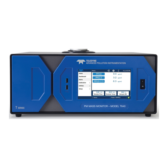
TELEDYNE T640 PM
DEPARTMENT OF ENVIRONMENTAL PROTECTION
Prepared by:
Florida PQAO
Approved by: _____________________________ Date: _______________________
Quality Assurance Manager
Approved by: _____________________________ Date: _______________________
EPA Region IV Approval Officer
STATEWIDE
STANDARD OPERATING
PROCEDURE
STATE OF FLORIDA
OFFICE OF AIR MONITORING
Document History
FOR
PARTICULATE MONITOR
2.5
Date: 11/6/2017
Advertisement
Table of Contents

Related Manuals for Teledyne T640


Summary of Contents for Teledyne T640
- Page 1 STATEWIDE STANDARD OPERATING PROCEDURE TELEDYNE T640 PM PARTICULATE MONITOR STATE OF FLORIDA DEPARTMENT OF ENVIRONMENTAL PROTECTION OFFICE OF AIR MONITORING Prepared by: Florida PQAO Date: 11/6/2017 Approved by: _____________________________ Date: _______________________ Quality Assurance Manager Approved by: _____________________________ Date: _______________________ EPA Region IV Approval Officer...
- Page 2 Revision No. Date Responsible Person Description of Change November 2017 Florida PQAO Initial Release...
-
Page 3: Table Of Contents
10.2.2 Flow Calibration ....................11 10.2.3 PMT Adjustment ....................12 11.0 MAINTENANCE PROCEDURES ..............13 11.1 Cleaning the T640 TSP Inlet..................14 11.2 Changing the Disposable Filter Unit (DFU) ..............15 11.3 Checking Pump Performance ..................17 11.4 Checking the Flow ......................17 11.5 Cleaning the Optical Chamber and the RH/T Sensor ...........17... - Page 4 List of Figures Figure 1 Pressure Verification Screen .................... 8 Figure 2 Sample Flow Verification....................9 Figure 3 PMT adjustment Screen ....................10 Figure 4 Pressure Calibration Screen .................... 11 Figure 5 Flow Calibration Screen ....................12 Figure 6 PMT Adjustment Screen ....................13 Figure 7 TSP Inlet .........................
-
Page 5: Purpose
PM2.5 [EQPM-0516-238] and PM10--2.5 [EQPM-0516-240], The T640 operates at a total flow 16.7 lpm and this SOP is written specifically for this method. The model T640 is an approved FEM for PM2.5 [EQPM-0516-236]. The T640 also measures PM10 and PM10-2.5, but only the... -
Page 6: Principles Of Operation
The T640 operates at 5.0 lpm with a TSP inlet. This configuration is approved as an FEM for PM2.5; however, it also provides data (not approved as an FEM) for PM10 and PM10-2.5. -
Page 7: Table 4-1 Terms And Definitions
DEP 03-21 Revision No. 0 November 2017 Table 4-1 Terms and Definitions Term Definition The degree of agreement between an observed value and an accepted Accuracy reference value; includes a combination of random error (precision) and systematic error (bias) components due to sampling and analytical operations. The actual ambient temperature and pressure of a gas at the time its volume Actual conditions (or volumetric flow rate) is measured. -
Page 8: Health And Safety Precautions
T640 into line power. High voltages are present inside the instrument. Ensure that the power cord being used can carry the power rating of the instrument (see rear panel label). Note: •... -
Page 9: Equipment And Supplies
Since detailed information for various procedures are contained in the manufacturer’s manual, it must be on hand during any operator interaction with the Teledyne T640 monitor. 9.1 Installation For the monitor to operate within EPA guidelines, the sample inlet must be located between 2 and 15 meters above ground level. -
Page 10: Site Setup
The T640 may be installed either in a monitoring shelter that contains existing monitoring equipment or in a separate outdoor enclosure. The T640’s acceptable shelter temperature range is 0 to 50º C. However, operating ambient air instruments at 25ºC or lower can create large moisture issues during the summer because of the presence of high ambient humidity. -
Page 11: Leak Test
5. PMT verification using SpanDust™. 10.1.1 Leak Test The internal components of the T640 are not meant to be under strict vacuum as what would normally be done in a leak test. So, to avoid damage to internal components, it is recommended that the inlet never be capped (air tight) while the instrument pump is running. -
Page 12: Ambient Temperature Verification
3. Record audit device ambient temperature and T640x ambient temperature to the “Monthly QC and Maintenance sheet”. 4. Compare audit to T640 ambient temperature and if off by more than +/-2C, troubleshoot and repeat. 5. If verification cannot meet tolerance replace temperature probe. -
Page 13: Pmt Verification
The Particle Sensor PMT Verification uses SpanDust™, a monodisperse dust with a specific refractive index. All T640 instrument PMTs have a very specific response to this span dust which allows for the sensor to be checked in the field for drift caused by contamination of the... -
Page 14: Instrument Calibration/Adjustment
2. Press the Start button on this screen to suspend normal data acquisition and start this adjustment process. 3. Remove the T640 sample inlet. 4. Prepare the SpanDust™ bottle by uncapping the “air intake” tubing on the cap of the bottle. -
Page 15: Pressure Sensor Calibration
November 2017 10.2.1 Pressure Sensor Calibration The pressure measurement of the T640 is for the ambient pressure in which the instrument is operated. No direct pneumatic connection to the instrument needs to be made to perform this calibration and data are not affected. -
Page 16: Pmt Adjustment
The Particle Sensor PMT Calibration uses SpanDust™, a monodisperse dust with a specific refractive index. All T640 instrument PMTs have a very specific response to this span dust which allows for the sensor to be adjusted in the field for drift caused by contamination of the optics. -
Page 17: Maintenance Procedures
11. Reattach the sample inlet and press the Stop button to stop the adjustment process and resume normal data acquisition. For more information on the PMT Adjustment, use the QR above to view a video by Teledyne API. 12. Wait 10 minutes, review data on home screen of T640x, and then bring unit back “On Scan”... -
Page 18: Cleaning The T640 Tsp Inlet
Quarterly or when Pimp PVM lpm sample flow and 11.67 lpm bypass flow value approaches 80%. (if installed) Inspect inner and outer sample tubes Monthly or as needed 11.1 Cleaning the T640 TSP Inlet For this procedure, ensure the channels are “In Maintenance”... -
Page 19: Changing The Disposable Filter Unit (Dfu)
This procedure should be repeated per the schedule in Table 6-1. 11.2 Changing the Disposable Filter Unit (DFU) There is one DFU on the T640 for the 5.0 lpm pump 1. Power off the internal pump from the control menu: Setup> Vars> Pump > Edit> Off... -
Page 20: Figure 8 Opening The Front Panel
DEP 03-21 Revision No. 0 November 2017 2. Remove screws at sides of front panel, if installed. 3. Pull open the instrument’s front panel, using the front panel finger grips (Figure 7) Figure 8 Opening the Front Panel 4. Noting its orientation, remove the old DFU by detaching from the pneumatic quick- connect fittings, and replace with a new DFU matching the orientation (Figure 8). -
Page 21: Checking Pump Performance
>Main Menu > Home >Dashboard. 11.3 Checking Pump Performance There is one pump associated with the T640 an internal (operating at 5 lpm). The 5 lpm pump must maintain proper flow for measurement accuracy. Check the performance level in the Dashboard (If the parameter is not found in the Dashboard, configure the Dashboard to add it;... -
Page 22: Figure 11 Location Of Optics Chamber And Rh/T Sensor
DEP 03-21 Revision No. 0 November 2017 3. Locate the optical cell, the cup at the bottom of optics chamber and its tubing, and the Relative Humidity and Temperature (RH/T) sensor (Figure 10). Figure 11 Location of Optics Chamber and RH/T Sensor... -
Page 23: Figure 12 Optical Chamber Disassembly
DEP 03-21 Revision No. 0 November 2017 Remove optical cell from optics chamber, and remove cup, including its tubing, from optics chamber bottom; detach RH/T sensor tubing from DFU filter (Figure 11). Figure 12 Optical Chamber Disassembly Clean the optics chamber interior surfaces, ensuring to include windows, with a lint-free cloth (Figure 12). -
Page 24: Inspecting The Sample Tubes
RH/T sensor and from RH/T sensor to the DFU filter, and reinstall the ASC support. Close instrument and power back online. Perform a PMT sensor check with the SpanDust™ (Section 4.1.4 of the T640 User Manual). 11.6 Inspecting the Sample Tubes Look inside the sample tubes for debris or dust on the walls. -
Page 25: Table 12-1 Alerts And Recommendations
DEP 03-21 Revision No. 0 November 2017 Table 12-1 Alerts and Recommendations Message Description Possible Solution(s) Normal power cycle occurred? If System Reset Warning raised when the system is reset not, check external power source. Check pneumatic fittings. Sample Flow The Sample Flow is greater than 5.25 lpm High Re-calibrate flow. -
Page 26: Flow Problems
PWM range (35% - 80%); • the DFU appear reasonably clean and changed within last 12 months. After making any adjustments, run a flow calibration and recheck the flow rate. If problems persist, contact Teledyne-API Technical Support for assistance.
Need help?
Do you have a question about the T640 and is the answer not in the manual?
Questions and answers