Table of Contents
Advertisement
Available languages
Available languages
Quick Links
Leggere attentamente le istruzioni prima di installare e utilizzare l'apparecchiatura.
Read the instructions carefully before installing and using the appliance.
Vor der Installation und Nutzung des Geräts müssen die Anleitungen aufmerksam durchgelesen werden.
Lire attentivement les instructions avant d'installer et d'utiliser l'appareil.
Léanse atentamente las instrucciones antes de instalar y utilizar el aparato.
Il mancato rispetto delle istruzioni fa decadere la garanzia del fabbricante.
In the event of failure to comply with the instructions, the manufacturer's warranty shall cease to apply.
Die Missachtung der Anleitungen hat den Verfall der vom Hersteller gewährten Garantie zur Folge.
Le non respect des instructions entraîne l'invalidation de la garantie du fabricant.
La inobservancia de las instrucciones provoca la invalidación de la garantía otorgada por el fabricante.
PENTOLA INDIRETTA "GAS"
GGAS INDIRECT HEATED BOILING PAN
DOPPELWANDIGER GASKOCHKESSEL
MARMITE CHAUFFE INDIRECTE "GAZ"
MARMITA INDIRECTA "GAS"
ISTRUZIONI PER L'UTILIZZATORE
1N1PI1G -1T1PI1G
1N1PI2G - 1T1PI2G
1N1PI1GA - 1T1PI1GA
1N1PI2GA - 1T1PI2GA
USE MANUAL
BEDIENSHANDBUCH
MANUEL D'UTILISATION
MANUAL DE USO
Italiano
GB
English
DE
Deutsch
FR
Français
ES
Español
Rev.1 07/2017
3320160
IT
Advertisement
Chapters
Table of Contents

Related Manuals for Angelo Po 1N1PI1G


Summary of Contents for Angelo Po 1N1PI1G
- Page 1 Le non respect des instructions entraîne l’invalidation de la garantie du fabricant. La inobservancia de las instrucciones provoca la invalidación de la garantía otorgada por el fabricante. PENTOLA INDIRETTA “GAS” 1N1PI1G -1T1PI1G GGAS INDIRECT HEATED BOILING PAN 1N1PI2G - 1T1PI2G...
- Page 2 Cautela - Avvertenza Importante Verifi care quotidianamente che i dispositivi Durante l’utilizzo di detergenti è obbligato- di sicurezza siano perfettamente installati ed rio utilizzare guanti in gomma, maschera anti effi cienti. inalazione ed occhiali di protezione secondo le norme di sicurezza vigenti. Importante Cautela - Avvertenza Alla fi ne di ogni cottura, dopo aver eff ettua-...
-
Page 3: Table Of Contents
SOMMARIO INFORMAZIONI GENERALI ........2 ISTRUZIONI E AVVERTENZE PER IL LETTORE ........2 SCOPO DEL MANUALE . -
Page 4: Informazioni Generali
INFORMAZIONI GENERALI ISTRUZIONI E AVVERTENZE PER IL LETTORE Per rintracciare facilmente gli argomenti specifi - Questo manuale contiene tutte le informazioni ci di interesse, consultare l’indice analitico posto necessarie ai destinatari eterogenei, cioè gli all’inizio del manuale. utilizzatori dell’apparecchiatura. SCOPO DEL MANUALE Questo manuale, che è... -
Page 5: Identificazione Fabbricante E Apparecchiatura
) Tipo di gas MODALITÀ DI RICHIESTA ASSISTENZA Per qualsiasi esigenza rivolgersi alle agenzie o alla sede centrale Angelo Po i cui riferimenti sono riportati nella sezione contatti del sito internet http://www.angelopo.com. Per ogni richiesta di assistenza tecnica, indicare i dati riportati sulla targhetta di identifi cazione ed il tipo di difetto riscontrato. -
Page 6: Informazioni Tecniche
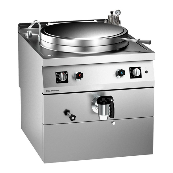
è prodotta in più versioni (vedi fi gura). preparazione e cottura di alimenti nell’ambito della ristorazione professionale. 1N1PI1G (100 lt) - 1T1PI1G (100 lt) 1N1PI1GA (100 lt) - 1T1PI1GA (100 lt) 1N1PI2G (150 lt) - 1T1PI2G (150 lt) 1N1PI2GA (150 lt) - 1T1PI2GA (150 lt) -
Page 7: Dispositivi Di Sicurezza
DISPOSITIVI DI SICUREZZA Anche se l’apparecchiatura è completa di tutti i dispositivi di sicurezza, in fase di installazione e allacciamento essi dovranno, se necessario, essere integrati con altri dispositivi nel rispetto delle leggi vigenti in materia. L’illustrazione indica la posizione dei dispositivi. Rubinetto alimentazione gas: serve per aprire e chiudere il collegamento alla linea di alimentazione gas. -
Page 8: Accessori A Richiesta
ACCESSORI A RICHIESTA A richiesta l’apparecchiatura può essere corredata dei seguenti accessori (vedi “catalogo generale”). SICUREZZA ISTRUZIONI E AVVERTENZE PER LA SICUREZZA Il fabbricante, in fase di progettazione e co- Utilizzare l’apparecchiatura solo per gli usi pre- struzione, ha posto particolare attenzione agli visti dal fabbricante. -
Page 9: Istruzioni E Avvertenze Per La Sicurezza Per L'impatto Ambientale
In caso di inattività prolungata, oltre a scollegare Cautela - Avvertenza tutte le linee di alimentazione, è necessario ef- fettuare una pulizia accurata di tutte le parti in- La pavimentazione, in prossimità dell’appa- terne ed esterne dell’apparecchiatura e dell’am- recchiatura potrebbe essere scivolosa. biente circostante, secondo le indicazioni fornite dal fabbricante e dalle leggi vigenti in materia. -
Page 10: Uso E Funzionamento
USO E FUNZIONAMENTO ISTRUZIONI E AVVERTENZE PER L’USO E FUNZIONAMENTO Importante Gli utilizzatori, oltre ad essere autorizzati ed Prima dell’uso verifi care che i dispositivi di opportunamente documentati, formati ed sicurezza siano perfettamente installati ed addestrati, se necessario, al primo uso, do- effi cienti. -
Page 11: Accensione E Spegnimento Bruciatore
ACCENSIONE E SPEGNIMENTO BRUCIATORE Accensione Aprire il rubinetto alimentazione gas. Premere e ruotare la manopola (A) in senso an- tiorario (pos. 1) e contemporaneamente man- tenere premuto il pulsante (B) per accendere la spia pilota. Mantenere premuta la manopola per circa 15 sec per consentire l’intervento della termocoppia. -
Page 12: Riempimento Intercapedine
RIEMPIMENTO INTERCAPEDINE Per questa operazione procedere nel modo indicato Aprire il rubinetto (A). Svitare il tappo (B). Ruotare l’erogatore dell’acqua (C) in corrispon- denza del raccordo di riempimento (D). Aprire i rubinetti (E) per riempire l’intercapedine. Quando l’acqua incomincia ad uscire dal rubinetto (A) chiudere i rubinetti (E) per non superare il livello di riempimento ottimale. -
Page 13: Inattività Prolungata Dell'apparecchiatura
INATTIVITÀ PROLUNGATA DELL’APPARECCHIATURA Se l’apparecchiatura rimane inattiva per un Cospargere con un velo d’olio alimentare le lungo tempo, procedere nel modo indicato. superfi ci in acciaio inox. Chiudere il rubinetto alimentazione gas. Eseguire tutte le operazioni di manutenzione. Agire sull’interruttore sezionatore dell’appa- Ricoprire l’apparecchiatura con un involucro recchiatura per disattivare l’allacciamento alla e lasciare alcune fessure per la circolazione... -
Page 14: Pulizia Apparecchiatura
PULIZIA APPARECCHIATURA Se si considera che l’apparecchiatura è utilizzata – Pulire accuratamente gli elementi che vengono per la preparazione di prodotti alimentari per a contatto direttamente o indirettamente con l’uomo, è necessario prestare particolare cura gli alimenti e tutte le zone limitrofe. a tutto ciò... -
Page 15: Rubinetto Di Scarico Tenuta Conica
RUBINETTO DI SCARICO TENUTA CONICA Uso e installazione L’utilizzo del rubinetto di scarico è limitato sola- mente all’evacuazione di liquidi per uso alimen- tare o liquidi per la preparazione di alimenti. Manutenzione Eseguire le operazioni di manutenzione e puli- zia dopo ogni utilizzo. Non utilizzare per tale scopo prodotti tossici o nocivi per la salute. -
Page 16: Guasti
Per qualsiasi esigenza rivolgersi alle agenzie l’identifi cazione e correzione di eventuali anomalie o alla sede centrale Angelo Po i cui riferimen- e disfunzioni che potrebbero presentarsi in fase ti sono riportati nella sezione contatti del sito d’uso. - Page 18 Importante Important Caution - Warning Make a daily check that the safety devices When using detergents, rubber gloves, pro- are properly installed and in good working tective mask and safety goggles must be order. worn in accordance with the relevant safety regulations.
- Page 19 SUMMARY GENERAL INFORMATION ........2 INSTRUCTIONS AND WARNINGS FOR THE READER .
-
Page 20: General Information
GENERAL INFORMATION INSTRUCTIONS AND WARNINGS FOR THE READER To fi nd the specifi c topics of interest to you This manual contains all of the required infor- quickly, refer to the index at the start of the mation for diff erent types of recipients, i.e. users manual. -
Page 21: Identification Of Manufacturer And Appliance
) Type of gas PROCEDURE FOR REQUESTING SERVICE For all requirements contact the agents or the headquarters of Angelo Po which can be found in the contacts section of the website http:// www.angelopo.com. When requesting service, state the data provide on the nameplate and provide a description of the fault. -
Page 22: Technical Information
(see diagram. constructed for preparing and cooking foods in the professional catering sector. 1N1PI1G (100 lt) - 1T1PI1G (100 lt) 1N1PI1GA (100 lt) - 1T1PI1GA (100 lt) 1N1PI2G (150 lt) - 1T1PI2G (150 lt) 1N1PI2GA (150 lt) - 1T1PI2GA (150 lt) -
Page 23: Safety Devices
SAFETY DEVICES Even if the equipment has all its safety devices, if necessary, during the installation and con- nection other safety devices may be supple- mented in accordance with applicable laws. The illustration shows the position of the devices. Gas supply tap: for turning the connection to the gas supply line on and off . -
Page 24: Optional Accessories
OPTIONAL ACCESSORIES The appliance can be equipped with the following accessories on request (see “General catalogue”). SAFETY SAFETY WARNINGS AND INSTRUCTIONS During design and construction, the manufac- All maintenance work that requires precise, turer has paid special attention to factors which technical expertise or particular skills or qualifi - may cause risks to the health and safety of the cations for legal reasons,should be carried out... -
Page 25: Safety Warnings And Instructions Concerning Environmental Impact
Do not leave fl ammable objects or materials in- Caution - Warning side or close to the appliance. Do not obstruct the fl ue to avoid the tem- Caution - Warning perature of the combustion components and The fl oor, near the appliance, could be products from increasing excessively over slippery. -
Page 26: Use And Operation
USE AND OPERATION INSTRUCTIONS AND WARNINGS FOR USE AND OPERATION Importante Important Besides being authorised and appropriately Before use, check that the safety devices documented,and if necessary,instructed and are properly installed and in good working trained, users,on fi rst usage, have to simulate order. -
Page 27: Switching The Burner On And Off
SWITCHING THE BURNER ON AND OFF Lighting Turn on the gas supply tap. Press and turn the knob (A) and turn it anti- clockwise (pos. 1), while keeping button (B) pressed, to light the pilot light. Keep the knob pressed for about 15 sec. to prime the thermocouple. -
Page 28: Filling The Jacket
FILLING THE JACKET To carry out this operation, proceed as follows. Turn on the tap (A). Unscrew the cap (B). Turn the water spout (C) towards the fi ller connection (D). Turn on the taps (E) to fi ll the jacket. When water starts to fl ow from the tap (A), turn off the taps (E) to avoid overfi lling. -
Page 29: Lengthy Downtimes Of Appliance
LENGTHY DOWNTIMES OF APPLIANCE If the appliance is to be out of use for a lengthy Spread a fi lm of edible oil over the stainless period, proceed as follows. steel surfaces. Turn off the gas supply tap. Carry out all the servicing procedures. Cut off the mains electricity supply using the Cover the appliance and leave a few gaps to appliance’s master switch. -
Page 30: Cleaning Instructions
CLEANING INSTRUCTIONS Since the appliance is used for preparing foods – After use, clean the accessories with a suitable for human consumption, special care must be grease-remover product. If possible, wash in paid to everything relating to hygiene, and the the dishwasher. -
Page 31: Drain Cock Conical Seal
DRAIN COCK CONICAL SEAL Use and installation This drain cock can be used only for discharging alimentary liquids or liquids for the production of foodstuff . Maintenance It’s advisable to perform cleaning and mainte- nance operations after every use. Do not use toxic or harmful chemicals. Perform maintenance and cleaning observing the following instructions. - Page 32 The information provided below is intended to For all requirements contact the agents or assist in the identifi cation and correction of any the headquarters of Angelo Po which can be anomalies and malfunctions which might occur found in the contacts section of the website during use.
- Page 34 Vorsicht - Achtung Importante Wichitig Stellen Sie jeden Tag durch Kontrollen sicher, Die geltenden Sicherheitsbestimmungen dass die Sicherheitsvorrichtungen fachgerecht schreiben vor, dass bei der Verwendung installiert sind und einwandfrei funktionieren. von Reinigungsmitteln Gummihandschuhe, Atemschutzmaske und Schutzbrille zu tragen Importante Wichitig sind.
- Page 35 INHALTSVERZEICHNIS ALLGEMEINES ..........2 ANWEISUNGEN UND WARNHINWEISE FÜR DEN LESER .
-
Page 36: Allgemeines
ALLGEMEINES ANWEISUNGEN UND WARNHINWEISE FÜR DEN LESER Konsultieren Sie das Sachregister, das am Dieses Handbuch enthält alle notwendigen Infor- Anfang des Handbuchs zu fi nden ist, um leichter mationen für unterschiedliche Benutzer, d.h. für unter bestimmten Themen von besonderem alle Nutzer des Geräts. Interesse nachschlagen zu können. -
Page 37: Typenschild Für Hersteller Und Gerät
KUNDENDIENST ANFORDERN Bei Rückfragen wenden Sie sich bitte an die Handelsvertretungen oder den Hauptsitz des Unternehmens Angelo Po, die entsprechenden Kontaktdaten sind auf der Webseite http://www. angelopo.com unter „Kontakt“ zu fi nden. Geben Sie bei jedem Kontakt mit dem Kunden-... -
Page 38: Technische Informationen
Zubereiten und Garen von Speisen in Abbildung). Restaurantbetrieben projektiert und konstruiert. 1N1PI1G (100 lt) - 1T1PI1G (100 lt) 1N1PI1GA (100 lt) - 1T1PI1GA (100 lt) 1N1PI2G (150 lt) - 1T1PI2G (150 lt) 1N1PI2GA (150 lt) - 1T1PI2GA (150 lt) -
Page 39: Sicherheitsvorrichtungen
SICHERHEITSVORRICHTUNGEN Auch wenn das Gerät mit allen Sicherheitsvor- richtungen ausgestattet ist, müssen im Rahmen der Aufstellung und des Anschlusses je nach Rechtslage ggf. weitere Vorrichtungen integriert werden. Die Abbildung zeigt die Anordnung der Sicherheitsvorrichtungen. Gashahn: um die Leitung für die Gaszufuhr zu öff nen oder abzusperren. -
Page 40: Optionales Zubehör
OPTIONALES ZUBEHÖR Auf Wunsch kann das Gerät mit folgenden Zubehörteilen ausgestattet werden. (“siehe Hauptkatalog”). SICHERHEIT ANWEISUNGEN UND WARNHINWEISE FÜR DIE SICHERHEIT Der Hersteller hat bei Entwicklung und Fertigung nen gefährden, Gegenstände, die sich in seiner dieses Produkts besondere Sorgfalt auf Aspekte Nähe befi nden, beschädigen und wirtschaftliche verwendet, die eine Gefahr für die Sicherheit und Schäden verursachen. -
Page 41: Anweisungen Und Warnhinweise Für Die In Hinblick Auf Die Umweltbela
Beim täglichen Gebrauch des Geräts ist die stän- Importante Wichitig dige Anwesenheit des Bedienungspersonals erforderlich. Die erforderlichen Anschlüsse (Wasser, Elek- Beim Waschen des Geräts den Wasserstrahl nicht trizität und Gas) dürfen ausschließlich von entsprechendem Fachpersonal gemäß den direkt auf die inneren Teile des Geräts richten. lokalen Vorschriften ausgeführt werden. -
Page 42: Gebrauch Und Betrieb
GEBRAUCH UND BETRIEB ANWEISUNGEN UND WARNHINWEISE FÜR DIE BEDIENUNG UND BETRIEB Die Geräte nur zu den vom Hersteller vorge- Importante Wichitig sehenen Zwecken verwenden und keinesfalls irgendwelche Vorrichtungen verändern, um Die Häufi gkeit von Unfällen aufgrund des Ge- andere als die vorgesehenen Leistungen zu er- brauchs von Geräten hängt von vielen Fakto- halten. -
Page 43: Ein- Und Ausschalten Des Brenners
EIN- UND AUSSCHALTEN DES BRENNERS Zündung Öff nen Sie den Gashahn. Schalter (A) niederdrücken und entgegen dem Uhrzeigersinn drehen (Pos. 1); gleichzeitig die Taste (B) zum Zünden des Zündfl ammenbren- ners gedrückt halten. Halten Sie den Bedien- knebel etwa 15 Sekunden lang gedrückt, damit das Thermoelement in Aktion treten kann. -
Page 44: Füllen Des Hohlraums
FÜLLEN DES HOHLRAUMS Für diesen Vorgang in der angegebenen Weise verfahren. Den Hahn (A) öff nen. Den Verschluss (B) ausschrauben. Das Wasserauslaufrohr (C) auf Höhe des Einfüll- anschlusses (D) drehen. Die Hähne (E) öff nen, um den Hohlraum zu füllen. Wenn das Wasser aus Hahn (A) auszutreten be- ginnt, die Hähne (E) wieder schließen, um nicht den optimalen Füllstand zu überschreiten. -
Page 45: Längerer Stillstand Des Geräts
LÄNGERER STILLSTAND DES GERÄTS Verfahren Sie folgendermaßen, falls das Gerät Tragen Sie eine hauchdünne Schicht Lebens- längere Zeit nicht eingesetzt werden soll: mittelöl auf die Edelstahlfl ächen auf. Schließen Sie den Gaszufuhrhahn. Führen Sie sämtliche Wartungsarbeiten aus. Das Gerät mit seinem Trennschalter vom Das Gerät mit einer Schutzhülle abdecken;... -
Page 46: Reinigung Des Geräts
REINIGUNG DES GERÄTS Da das Gerät zur Zubereitung von Speisen für – Die Zubehörteile nach dem Gebrauch mit den Menschen eingesetzt wird, ist besondere einem geeigneten Fettlöser reinigen. Wir Sorgfalt auf die Hygiene geboten. Das Gerät und empfehlen die Reinigung im Geschirrspüler. dessen näheres Umfeld müssen konstant sauber gehalten werden. -
Page 47: Hahn Drain Seal Kegel
HAHN DRAIN SEAL KEGEL Bedien- Und Installations Die Verwendung des Auslaßventils nur für die Evakuierung von Flüssigkeiten für die Herstel- lung von Lebensmitteln zur Verwendung als Lebensmittel oder Flüssigkeiten beschränkt. Wartung Führen Sie die Wartung und Reinigung nach jedem Gebrauch. Nicht für diesen Zweck oder toxische Produkte schädlich für die Gesundheit nutzen. - Page 48 Bei Rückfragen wenden Sie sich bitte an die sollen Ihnen dabei helfen, eventuelle Anomali- Handelsvertretungen oder den Hauptsitz en oder Funktionsstörungen, die während des des Unternehmens Angelo Po, die entspre- Betriebs auftreten können, aufzufi nden und zu chenden Kontaktdaten sind auf der Websei- beheben.
- Page 50 Attention Importante Important Vérifi er quotidiennement que les dispositifs Lorsqu’on utilise des détergents, il est obli- de sécurité soient parfaitement installés et gatoire de porter des gants en caoutchouc, effi caces. un masque de protection respiratoire et des lunettes de protection conformément aux Importante Important normes de sécurité...
- Page 51 INDEX INFORMATIONS GENERALES ....... . . 2 INSTRUCTIONS ET AVERTISSEMENTS POUR LE LECTEUR ......2 SCOPO DEL MANUALE .
- Page 52 INFORMATIONS GENERALES INSTRUCTIONS ET AVERTISSEMENTS POUR LE LECTEUR Pour retrouver facilement les sujets qui vous Ce manuel contient toutes les informations intéressent, consulter l’index analytique au nécessaires aux destinataires hétérogènes, c’est- début du manuel. à-dire les utilisateurs de l’appareil. SCOPO DEL MANUALE Ce manuel, qui fait partie intégrante de l’appa- Le fabricant se réserve le droit d’apporter des reil, a été...
- Page 53 ) Type de gaz DEMANDE D’ASSISTANCE Pour toute exigence, s’adresser aux agences ou au siège centra Angelo Po dont les références sont reportées dans la section contacts du site internet http://www.angelopo.com. Pour toute demande d’assistance technique, indiquer les données reportées sur la plaque d’identifi cation et le type de défaut relevé.
- Page 54 1N1PI1G (100 lt) - 1T1PI1G (100 lt) 1N1PI1GA (100 lt) - 1T1PI1GA (100 lt) 1N1PI2G (150 lt) - 1T1PI2G (150 lt) 1N1PI2GA (150 lt) - 1T1PI2GA (150 lt)
- Page 55 DISPOSITIFS DE SÉCURITÉ Même si l’équipement comprend tous les dis- positifs de sécurité, en phase d’installation et de branchement ils devront, si nécessaire, être inté- grés avec des autres dispositifs dans le respect des lois en vigueur à ce propos. L’illustration indique la position des dispositifs.
- Page 56 ACCESSOIRES SUR DEMANDE Sur demande l’appareil peut être équipé des accessoires suivants (“voir le catalogue général”). SÉCURITÉ INSTRUCTIONS ET MISES EN GARDE POUR LA SÉCURITÉ Le fabricant, lors de la conception et de la Toutes les interventions de maintenance qui fabrication, a fait très attention aux aspects qui nécessitent une compétence technique précise peuvent provoquer des risques à...
- Page 57 Pendant le lavage de l’appareil ne pas diriger Attention de jets d’eau sous pression sur les pièces inté- rieures. Ne pas obstruer la cheminée pour éviter Ne pas laisser d’objets ou de matériau infl am- l’augmentation excessive de la température mable à...
- Page 58 UTILISATION ET FONCTIONNEMENT INSTRUCTIONS ET AVERTISSEMENTS POUR L’UTILISATION ET FONCTIONNEMENT Importante Important Les utilisateurs, en plus d’être autorisés et Avant l’utilisation, vérifi er si les dispositifs de documentés de façon appropriée, formés et sécurité sont parfaitement installés et effi - entraînés, si nécessaire, lors de la première caces.
- Page 59 ALLUMAGE ET EXTINCTION DU BRULEUR Allumage Ouvrir le robinet d’alimentation du gaz. Pousser et tourner la manette (A) en sens anti- horaire (pos. 1) et simultanément tenir pressé le bouton (B) pour allumer la veilleuse pilote pilota. Continuer à appuyer sur la manette pendant environ 15 s pour permettre l’intervention du thermocouple.
- Page 60 REMPLISSAGE INTER PAROIS Pour cette opération, procéder comme suit. Ouvrir le robinet (A). Dévisser le bouchon (B). Tourner l’érogateur de l’eau (C) en correspon- dance du raccord de remplissage (D). Ouvrir les robinets (E) pour remplir l’inter parois. Lorsque l’eau commence à sortir du robinet (A) fermer les robinets (E) pour ne pas dépasser le niveau de remplissage optimal.
- Page 61 INUTILISATION PROLONGÉE DE L’APPAREIL Si l’appareil reste inactif pendant longtemps, Étaler un voile d’huile alimentaire sur les procéder comme suit. surfaces en acier inox. Fermer le robinet d’alimentation du gaz. Exécuter toutes les opérations d’entretien. Agir sur l’interrupteur sectionneur de l’appa- Recouvrir l’appareil d’une protection et laisser reil pour désactiver le branchement à...
- Page 62 NETTOYAGE DE L’APPAREIL Étant donné que l’appareil est utilisé pour – Nettoyer soigneusement les éléments qui sont la préparation de produits alimentaires pour en contact direct ou indirect avec les aliments l’homme, il faut faire attention à tout ce qui et toutes les zones avoisinantes.
- Page 63 ROBINET DE VIDANGE JOINT CONE Utilisation et d’installation L’utilisation de robinet du vidange est limité uniquement à l’évacuation des liquides destinés à l’usage alimentaire ou des liquides pour la préparation d’aliments. Entretien Eff ectuer l’entretien et le nettoyage après chaque utilisation. Ne pas utiliser à...
- Page 64 à l’identifi cation et à la correction Pour toute exigence, s’adresser aux agences d’éventuels pannes et dysfonctionnements qui ou au siège centra Angelo Po dont les ré- pourraient se présenter en cours d’utilisation. férences sont reportées dans la section Certains de ces problèmes peuvent être résolus...
- Page 66 Precaución - advertencia Importante Importante Controlar periódicamente que los equipos de Al aplicar los detergentes es obligatorio utili- seguridad se encuentren en perfecto estado zar guantes en goma, mascarilla contra inha- y estén correctamente instalados. laciones y gafas de protección, en conformi- dad con lo dispuesto por las normas vigentes Importante Importante...
- Page 67 ÍNDICE INFORMACIONES DE CARÁCTER GENERAL ....2 INSTRUCCIONES Y ADVERTENCIAS PARA EL LECTOR ......2 OBJETIVO DEL MANUAL .
-
Page 68: Informaciones De Carácter General
INFORMACIONES DE CARÁCTER GENERAL INSTRUCCIONES Y ADVERTENCIAS PARA EL LECTOR Para ubicar fácilmente los temas específi cos Este manual incluye toda la información necesa- de interés, consúltese el índice analítico que se ria para los destinatarios heterogéneos, es decir, encuentra al inicio del manual. para los usuarios del equipo. -
Page 69: Identificación Fabricante Y Equipo
) Tipo de gas MODALIDAD PARA REQUERIR ASISTENCIA Para cualquier necesidad, diríjase a las agencias o a la sede central de Angelo Po, cuyos referen- tes se indican en la sección de contactos del sitio web http://www.angelopo.com. Para solicitar asistencia técnica deberán indicarse los datos reproducidos en la placa de identifi cación y el tipo de desperfecto que se ha... -
Page 70: Informaciones De Carácter Técnico
(véase fi gura). tos en el sector de la restauración profesional. 1N1PI1G (100 lt) - 1T1PI1G (100 lt) 1N1PI1GA (100 lt) - 1T1PI1GA (100 lt) 1N1PI2G (150 lt) - 1T1PI2G (150 lt) 1N1PI2GA (150 lt) - 1T1PI2GA (150 lt) Órganos principales... -
Page 71: Dispositivos De Seguridad
DISPOSITIVOS DE SEGURIDAD Aunque el equipo cuente con todos los dispo- sitivos de seguridad, en los casos en que así lo determinen las leyes vigentes en materia, se deberá complementar con otros dispositivos en las fases de instalación y enlace. La ilustración indica la posición de los disposi- tivos. -
Page 72: Accesorios Bajo Pedido
ACCESORIOS BAJO PEDIDO Bajo pedido, el equipo puede ser suministrado con los accesorios que a continuación se indican (“vea el catálogo general”). SEGURIDAD INSTRUCCIONES Y ADVERTENCIAS PARA LA SEGURIDAD Durante las fases de diseño y producción el Todas las operaciones de mantenimiento que fabricante ha prestado especial atención a los requieran una competencia técnica específi ca o factores que pueden provocar riesgos en cuanto... -
Page 73: Instrucciones Y Advertencias De Seguridad Para El Impacto
Durante el lavado del aparato no dirigir chorros Importante Importante de agua a presión hacia sus partes internas. No dejar objetos o material infl amable en el in- Las conexiones necesarias (agua, electricidad terior del compartimiento ni en proximidad del y gas) se deben realizar exclusivamente por aparato. -
Page 74: Uso Y Funcionamiento
USO Y FUNCIONAMIENTO INSTRUCCIONES Y ADVERTENCIAS PARA EL USO Y FUNCIONAMIENTO Antes del uso, controlar que los dispositivos de Importante Importante seguridad estén instalados de forma correcta y efi caz. Los utilizadores, además de estar autorizados y oportunamente documentados, formados y Los usuarios, además de obligarse a cumplir es- adiestrados, si fuera necesario, con el primer uso, tos requisitos, deben aplicar todas las normas... -
Page 75: Encendido Y Apagado Del Quemador
ENCENDIDO Y APAGADO DEL QUEMADOR Encendido Abrir el grifo de alimentación del gas. Presionar y hacer girar el mando (A) en sentido antihorario (pos. 1) manteniendo simultánea- mente presionado el botón (B) para encender el piloto. Mantener presionado el mando du- rante aprox. -
Page 76: Riempimento Intercapedine
RIEMPIMENTO INTERCAPEDINE Para efectuar esta operación, aplicar las siguien- tes instrucciones. Abrir el grifo (A). Desenroscar el tapón (B). Girar el grifo del agua (C) en correspondencia con el racor de llenado (D). Abrir los grifos (E) para llenar la cámara de aire. Cuando el agua comienza a salir por el grifo (A) cerrar los grifos (E) para no superar el nivel apropiado de llenado. -
Page 77: Período Prolongado De Inactividad Del Equipo
PERÍODO PROLONGADO DE INACTIVIDAD DEL EQUIPO En caso de que el equipo deba permanecer inac- Esparcir sobre las superfi cies de acero inoxida- tivo durante un período prolongado de tiempo, ble una capa delgada de aceite comestible. se deberán efectuar las siguientes operaciones. Efectuar todas las operaciones de manteni- Cerrar el grifo de alimentación del gas. -
Page 78: Limpieza Aparato
LIMPIEZA APARATO Atendida la circunstancia de que el equipo es – Limpiar los accesorios después del uso utilizado para la preparación de productos ali- utilizando un desengrasante adecuado. Se menticios para el consumo humano, es necesa- aconseja efectuar el lavado en lavavajillas. rio prestar especial atención a todo lo referente Precaución - advertencia a la higiene, manteniendo siempre limpio tanto... -
Page 79: Grifo De Descarga Cónico
GRIFO DE DESCARGA CÓNICO. Uso y Instalación El uso del grifo descarga se limita sólo a la evacuación de líquidos para uso alimentos o líquidos para la preparación de alimentos. Mantenimiento. Realizar el mantenimiento y la limpieza después de cada uso. No utilice para este fi n o productos tóxicos perjudiciales para la salud. -
Page 80: Averías
Las siguientes informaciones tienen por objeto Per qualsiasi esigenza rivolgersi alle agenzie facilitar la identifi cación y corrección de even- o alla sede centrale Angelo Po i cui riferimen- tuales anomalías y disfunciones que podrían ti sono riportati nella sezione contatti del sito presentarse durante el uso. - Page 81 Le non respect des instructions entraîne l’invalidation de la garantie du fabricant. La inobservancia de las instrucciones provoca la invalidación de la garantía otorgada por el fabricante. PENTOLA INDIRETTA “GAS” 1N1PI1G -1T1PI1G GGAS INDIRECT HEATED BOILING PAN 1N1PI2G - 1T1PI2G...
- Page 83 SOMMARIO INFORMAZIONI GENERALI ........3 ISTRUZIONI E AVVERTENZE PER IL LETTORE ........3 SCOPO DEL MANUALE .
- Page 84 TRASFORMAZIONE ALIMENTAZIONE GAS ........13 COLLAUDO APPARECCHIATURA .
-
Page 85: Informazioni Generali
INFORMAZIONI GENERALI ISTRUZIONI E AVVERTENZE PER IL LETTORE Per rintracciare facilmente gli argomenti specifi - Questo manuale contiene tutte le informazioni ci di interesse, consultare l’indice analitico posto necessarie ai destinatari omogenei, cioè tutti gli all’inizio del manuale. operatori esperti e autorizzati a movimentare, tra- sportare, installare, mantenere, riparare, e demoli- re l’apparecchiatura. -
Page 86: Modalità Di Richiesta Assistenza
) Tipo di gas MODALITÀ DI RICHIESTA ASSISTENZA Per qualsiasi esigenza rivolgersi alle agenzie o alla sede centrale Angelo Po i cui riferimenti sono riportati nella sezione contatti del sito internet http://www.angelopo.com. Per ogni richiesta di assistenza tecnica, indicare i dati riportati sulla targhetta di identifi cazione ed il tipo di difetto riscontrato. -
Page 87: Informazioni Tecniche
INFORMAZIONI TECNICHE DESCRIZIONE GENERALE APPARECCHIATURA Vedi paragrafo “DESCRIZIONE GENERALE APPARECCHIATURA” del manuale Istruzioni per l’utilizzatore. DISPOSITIVI DI SICUREZZA Vedi paragrafo “DISPOSITIVI DI SICUREZZA” del manuale Istruzioni per l’utilizzatore DATI TECNICI Vedi tabella e “scheda allacciamenti” in fondo al manuale. SEGNALI DI SICUREZZA E INFORMAZIONE Vedi paragrafo “SEGNALI DI SICUREZZA E INFORMAZIONE”... -
Page 88: Controllo Pressione Gas
MANUTENZIONE ISTRUZIONI ED AVVERTENZE PER LA MANUTENZIONE Mantenere l’apparecchiatura in condizioni di ed impedire l’accesso a tutti i dispositivi che massima effi cienza, grazie alle operazioni di potrebbero, se attivati, provocare condizio- manutenzione programmata previste dal fab- ni di pericolo inatteso causando danni alla bricante. -
Page 89: Guasti
GUASTI RICERCA GUASTI Vedi paragrafo “Ricerca guasti” del manuale Istru- zioni per l’utilizzatore. MOVIMENTAZIONE E INSTALLAZIONE ISTRUZIONI ED AVVERTENZE PER LA MOVIMENTAZIONE E INSTALLAZIONE Tutte le operazioni di movimentazione e di Importante installazione dovranno essere eseguite nel ri- Eseguire la movimentazione e l’installazio- spetto della legislazione vigente in materia di ne nel rispetto delle informazioni fornite dal salute e sicurezza sul lavoro. -
Page 90: Movimentazione E Sollevamento
MOVIMENTAZIONE E SOLLEVAMENTO L’apparecchiatura può essere movimentata con un dispositivo di sollevamento a forche o a gan- cio di portata adeguata. Prima di eff ettuare que- sta operazione, controllare la posizione del bari- centro del carico. Importante Nell’inserire il dispositivo di sollevamento, fare attenzione ai tubi di alimentazione e sca- rico. -
Page 91: Installazione Parti Smontate
INSTALLAZIONE PARTI SMONTATE Ingrassare i 2 Oring ( A e B) posizionati sul tubo di scarico ( C ). Inserire la Flangia (D) . Inserire il rubinetto (E) in battuta sul tubo di scarico (C). Posizionare, in verticale, il rubinetto (E) e bloccare i 3 grani M6 (F). -
Page 92: Livellamento
LIVELLAMENTO Agire sui piedi di appoggio (A) per livellare l’ap- parecchiatura. ALLACCIAMENTO ACQUA Per eff ettuare l’allacciamento, collegare il tubo di rete con il tubo di attacco dell’apparecchiatu- ra, interponendo un rubinetto di intercettazione per interrompere, quando necessario, l’ali- mentazione dell’acqua. A valle di esso installare dei fi ltri facilmente rag- giungibili. -
Page 93: Allacciamento Gas
ALLACCIAMENTO GAS Importante Chi è autorizzato ad eff ettuare tale operazio- ne deve possedere capacità ed esperienza acquisita e riconosciuta nel settore specifi co, dovrà eseguire l’allacciamento a regola d’ar- te e tenere conto di tutti i requisiti normati- vi e legislativi. Ad allacciamento completato, prima di rendere operativa l’attrezzatura, si dovrà... -
Page 94: Allacciamento Elettrico
ALLACCIAMENTO ELETTRICO Aprire il portello (B). Importante Svitare la vite (C) per smontare il coperchio (D). L’apparecchiatura è già provvista di cavo per Collegare l’interruttore sezionatore (A) alla l’allacciamento all’interruttore sezionatore. morsettiera (E)dell’apparecchiatura come Nel caso si ravvisi la necessità di sostituire il indicato in fi gura e nello schema elettrico in cavo procedere come descritto di seguito. -
Page 95: Trasformazione Alimentazione Gas
TRASFORMAZIONE ALIMENTAZIONE GAS Cautela - Avvertenza Prima di eseguire qualsiasi intervento disatti- vare l’alimentazione elettrica generale. L’apparecchiatura è stata collaudata dal fabbri- cante con il proprio gas di rete, segnalato dall’a- desivo applicato sulla targhetta di identifi cazione. Se il tipo di gas da allacciare è diverso da quello di collaudo, procedere nel modo indicato. -
Page 96: Regolazioni
REGOLAZIONI ISTRUZIONI ED AVVERTENTE PER LE REGOLAZIONI dell’apparecchiatura ed impedire l’accesso a Importante tutti i dispositivi che potrebbero, se attivati, Prima di eff ettuare qualsiasi tipo di regolazio- provocare condizioni di pericolo inatteso cau- ne, attivare tutti i dispositivi di sicurezza previ- sando danni alla sicurezza e alla salute delle sti e valutare se sia necessario informare ade- persone. -
Page 97: Regolazione Aria Primaria Bruciatore
REGOLAZIONE ARIA PRIMARIA BRUCIATORE Per questa operazione procedere nel modo in- dicato. Chiudere il rubinetto alimentazione gas. Aprire il portello (A). Allentare la vite di bloccaggio (B) della ghiera (C). Regolare la posizione della ghiera (C) alla distanza (D) riportata in tabella. Famiglia gas Distanza (D) (mm) II (G25/20-25 mbar) -
Page 98: Ingrassaggio Rubinetto Gas
INGRASSAGGIO RUBINETTO GAS Per questa operazione procedere nel modo in- dicato. Chiudere il rubinetto alimentazione gas. Sfi lare le manopole (A). Smontare i gruppi manopole (B). Svitare le viti (C) e smontare il cruscotto (D). Svitare le viti (E) ed estrarre la calotta (F). Sfi lare il cono (G). -
Page 99: Sostituzione Ugello Spia Pilota
SOSTITUZIONE UGELLO SPIA PILOTA Per questa operazione procedere nel modo indicato. Chiudere il rubinetto alimentazione gas. Aprire il portello (A). Svitare il raccordo (B). Estrarre l’ugello (C) e sostituirlo con quello adatto al tipo di gas utilizzato (vedi tabella in fondo al manuale). - Page 101 SUMMARY GENERAL INFORMATION ........3 INSTRUCTIONS AND WARNINGS FOR THE READER .
- Page 102 CONVERSION OF GAS SUPPLY ..........13 TESTING OF THE APPLIANCE .
-
Page 103: General Information
GENERAL INFORMATION INSTRUCTIONS AND WARNINGS FOR THE READER To fi nd the specifi c topics of interest to you This manual contains all of the required informa- quickly, refer to the index at the start of the tion for diff erent types of recipients, i.e. operators manual. -
Page 104: Procedure For Requesting Service
11 ) Rated power (kW) PROCEDURE FOR REQUESTING SERVICE For all requirements contact the agents or the he- adquarters of Angelo Po which can be found in the contacts section of the website http://www. angelopo.com. When requesting service, state the data provide on the nameplate and provide a description of the fault. -
Page 105: Technical Information
TECHNICAL INFORMATION GENERAL DESCRIPTION OF APPLIANCE See paragraph “GENERAL DESCRIPTION OF APPLI- ANCE” of the User instructions manual. SAFETY DEVICES See paragraph “SAFETY DEVICES” of the User in- structions manual. TECHNICAL DATA See tables and “Connection chart” at the back of the manual. -
Page 106: Checking Gas Pressure
SERVICING INSTRUCTIONS AND WARNINGS FOR SERVICING Keep the appliance at peak effi ciency by car- Also make sure that during the maintenance rying out the scheduled servicing procedures procedure, that the operator is always able to recommended by the manufacturer. Proper ser- check whether the plug is disconnected from vicing will allow the best performance, a longer the power outlet. -
Page 107: Fault
FAULT TROUBLESHOOTING See paragraph “TROUBLESHOOTING” of the User instructions manual. HANDLING AND INSTALLATION INSTRUCTIONS AND WARNINGS FOR HANDLING AND INSTALLATION use. All handling and installation operations Importante Important should be carried out in accordance with cur- When handling and installing the appliance rent legislation on health and safety at work. -
Page 108: Handling And Lifting
HANDLING AND LIFTING The appliance can be handled using fork-lift or hook equipment of suitable load-carrying ca- pacity. Before lifting, check the position of the load’s centre of gravity. Importante Important When engaging with the lifting equipment, watch out for the gas supply pipe. INSTALLATION OF THE APPLIANCE All installation stages must be considered right from production of the general layout. -
Page 109: Installation Of Dismantled Parts
INSTALLATION OF DISMANTLED PARTS Grease the 2 O-rings ( A and B) mounted on the drain pipe (C). Insert the fl ange (D). Insert the cock (E) up to the stop on the drain pipe (C). Place the cock (E) vertically and block the 3 M6 dowels (F). -
Page 110: Levelling
LEVELLING Adjust the fl oor-mounted feet (A) to level the ap- pliance. WATER CONNECTION To make the connection, connect the mains line to the appliance’s connection pipe, fi tting a shut-off tap (A), to allow the water supply to be cut off when necessary. -
Page 111: Gas Connection
GAS CONNECTION Importante Important Those authorised to carry out this operation must have experience acquired and certifi ed in the specifi c sector, must make the connec- tion to the proper standards, and must com- ply with all the relevant regulations and leg- islation. -
Page 112: Electrical Connection
ELECTRICAL CONNECTION If not already present, install a circuit-breaker Importante Important (A) with overload cutout and diff erential safety breaker close to the appliance. The equipment comes with a cable to con- Open the hatch (B). nect it to the outlet of the disconnecting Undo the screws (C) to remove the lid (D). -
Page 113: Conversion Of Gas Supply
CONVERSION OF GAS SUPPLY Caution - Warning Before doing any work, cut off the mains elec- tricity supply. The manufacturer has tested the appliance with its own mains gas, identifi ed by the sticker ap- plied to the nameplate. If the type of gas to be connected is diff erent from that used for testing, proceed as follows. -
Page 114: Adjustments
ADJUSTMENTS INSTRUCTIONS AND WARNINGS FOR ADJUSTMENTS cause unexpected health and safety hazards Importante Important if turned on. Before making any type of adjustment, acti- Caution - Warning vate all the safety devices provided and de- cide whether staff at work and those in the Adjustments must be carried out by author- vicinity should be informed. -
Page 115: Adjusting Burner Primary Air
ADJUSTING BURNER PRIMARY AIR To carry out this operation, proceed as follows. Turn off the gas supply tap. Open the hatch (A). Back off the screw (B) which secures the ring nut (C). Set the ring nut (C) at the distance (D) shown in the table. -
Page 116: Greasing The Gas Tap
GREASING THE GAS TAP To carry out this operation, proceed as follows. Turn off the gas supply tap. Pull off the knob (A). Remove the knob unit (B). Undo the screws (C) and remove the control panel (D). Undo the screws (E) and extract the cap (F). Pull off the cone (G). -
Page 117: Replacement Of The Pilot Light Injector
REPLACEMENT OF THE PILOT LIGHT INJECTOR To carry out this operation, proceed as follows. Turn off the gas supply tap. Open the hatch (A). Unscrew the union (B). Remove the nozzle (C) and replace it with the one suitable for the type of gas in use (see table at back of manual). - Page 118 ALLEGATI - ANNEXES Bruciatore Consumo gas - Gas consumption Vasca Burner Modello Allacciamento elettrico Well Model Electrical connection G25.1 12 kW (100 lt) (Min.5 kW) G25.3 1*1PI1G 2,54 m /h 2,95 m /h 1,89 kg/h 1,86 kg/h 0,6 W - 230V1N 50/60Hz –...
- Page 119 Bruciatore Consumo gas - Gas consumption Vasca Burner Modello Allacciamento elettrico Well Model Electrical connection G25.1 12 kW (150 lt) (Min.5 kW) G25.3 1*1PI2G N.1) 2,54 m /h 2,95 m /h 1,89 kg/h 1,86 kg/h 0,6 W - 230V1N 50/60Hz –...
- Page 120 Bruciatore Consumo gas - Gas consumption Vasca Burner Modello Allacciamento elettrico Well Model Electrical connection G25.1 12 kW (100 lt) (Min.5 kW) G25.3 1*1PI1GA 2,54 m /h 2,95 m /h 1,89 kg/h 1,86 kg/h 0,6 W - 230V1N 50/60Hz – La massima pressione sonora è inferiore a 70 dB. –...
- Page 121 Bruciatore Consumo gas - Gas consumption Vasca Burner Modello Allacciamento elettrico Well Model Electrical connection G25.1 12 kW (150 lt) (Min.5 kW) G25.3 1*1PI2GA 2,54 m /h 2,95 m /h 1,89 kg/h 1,86 kg/h 0,6 W - 230V1N 50/60Hz – La massima pressione sonora è inferiore a 70 dB. –...
- Page 122 SCHEMA ELETTRICO - ELECTRIC DIAGRAM 230V 1N Morsettiera - Terminal board. Pulsante accensione - Ignition button Gruppo accensione - Ignition unit. Candeletta piastra - Plate plug - V -...
- Page 123 Tabella iniettori bruciatore - Burner injector table p(3) p (7) Ø (4) Ø (5) Ø (6) Ø (8) mbar mbar mbar G30/G31 28-30/37 II2H3+ G30/G31 II 2H3B/P G30/G31 II2H3B/P G30/G31 28-30/37 II2E+3+ G30/G31 30/37 II2H3+ G30/G31 II2H3B/P G30/G31 28-30/37 II2H3+ G30/G31 II2H3B/P G30/G31...
- Page 124 Tabella iniettori bruciatore - Burner injector table p(3) p (7) Ø (4) Ø (5) Ø (6) Ø (8) mbar mbar mbar 28-30/37 II2E+3+ G30/G31 28-30/37 II2H3+ G30/G31 28-30/37 II2H3+ G30/G31 II2H3B/P G30/G31 II2HS3B/P G25.1 G30/31 28-30/37 II2H3+ G30/31 28-30/37 II2H3+ G30/G31 II2H3B/P G30/G31...
- Page 125 Tabella iniettori bruciatore - Burner injector table p(3) p (7) Ø (4) Ø (5) Ø (6) Ø (8) mbar mbar mbar G30/G31 28-30/37 II2H3+ G30/G31 II2H3B/P G30/G31 II2L3B/P G30/G31 II2EK3B/P G25.3 G30/G31 II2H3B/P G30/G31 II2H3B/P G30/G31 28-30/37 II2H3+ G30/G31 II2H3B/P G30/G31 28-30/37 II2H3+...
- Page 126 Tabella caratteristiche gas - Table of gas characteristics Potere calorifi co inferiore (Hi) Famiglia Tipo di gas Indice Wobbe (MJ/m3) Net calorifi c value (Hi) Group Gas type Wobbe index (MJ/m3) Kcal/m3 MJ/m3 Kcal/Kg Mj/Kg 45,67 8127 34,02 37,38 6988 29,25 G25.1 35,25...
- Page 128 Angelo Po Grandi Cucine S.p.A. con socio unico - Sede Centrale s.s. Romana Sud 90/F - 41012 Carpi (Mo) - Italy Tel: +39 059 639411 Fax: +39 059 642499 www.angelopo.com IT - È vietata la riproduzione, anche parziale, di questo documento senza il consenso del fabbricante. Egli è impegnato in una politica di continuo mi- glioramento e si riserva il diritto di modifi care questa documentazione senza l’obbligo di preavviso purché...
Need help?
Do you have a question about the 1N1PI1G and is the answer not in the manual?
Questions and answers