Table of Contents
Advertisement
Quick Links
Advertisement
Table of Contents

Related Manuals for Angelo Po 0G1CP1G


Summary of Contents for Angelo Po 0G1CP1G
- Page 1 PASTA COOKER 0G1CP1G USE AND INSTALLATION MANUAL 3015260...
- Page 2 Contact for Sales or Service: Angelo Po Catering Equipment Unit 4, 15-17 Heatherdale Road. Ringwood, Victoria 3134. Telephone: (03) 9874 0440 Facsimile: (03) 9874 0330...
-
Page 3: Table Of Contents
CONTENTS ref. chapters page 0 INFORMATION FOR THE READER ........2 1 GENERAL INFORMATION ..........2 2 TECHNICAL INFORMATION ..........3 3 SAFETY ................5 PART 4 USE AND OPERATION ............5 5 SERVICING ................ 7 6 FAULT ................. 9 7 HANDLING AND INSTALLATION........ -
Page 4: Information For The Reader
INFORMATION FOR THE READER To find the specific topics of interest to you quickly, re- part: contains all the information necessary fer to the index at the start of the manual. for special categories of reader, i.e. all skilled op- This manual is subdivided into two parts. -
Page 5: Technical Information
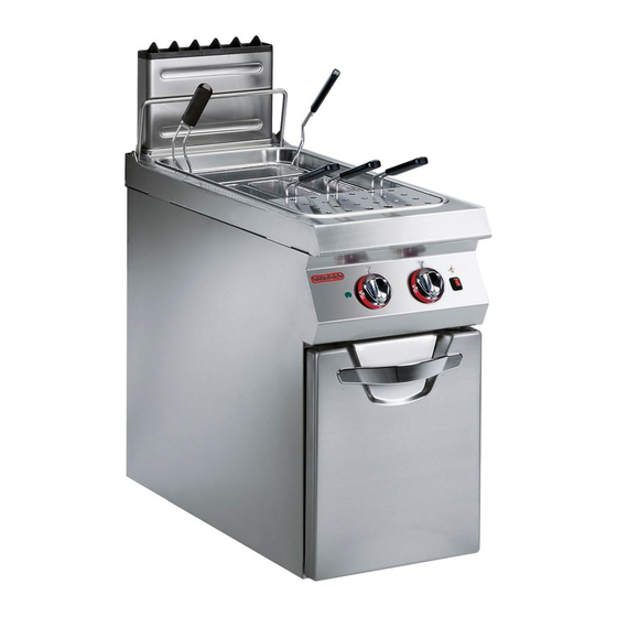
PROCEDURE FOR REQUESTING SERVICE Contact one of the authorised service centres for all When requesting service, state the data provide on requirements. the nameplate and provide a description of the fault. TECHNICAL INFORMATION GENERAL DESCRIPTION OF THE APPLIANCE The pasta cooker (referred to below as the appliance) is designed and constructed to cook pasta for human consumption in water, in the professional catering sector. - Page 6 SAFETY DEVICES Although the appliance is complete with all safety de- vices, during installation and connection additional devices must be added if necessary to comply with the relevant legal requirements. The illustration shows the position of the devices. A)Gas supply tap; for turning the connection to the gas supply line on and off.
-
Page 7: Safety
SAFETY SAFETY REGULATIONS During design and construction, the constructor has Use the appliance only for the functions intended by the manufacturer. Improper use of the appliance may paid special attention to factors which may cause involve health and safety risks and economic losses. risks to the health and safety of the people interacting with the appliance. - Page 8 DESCRIPTION OF CONTROLS Piezoelectric ignition marker Off marker Pilot light marker Full power marker Minimum power marker IDM-39603306100.tif The appliance is fitted with the controls for use of light. its main functions. B)Water tap: for regulating the flow of water. A)Burner control knob: for lighting, turning off C)Piezoelectric ignition knob: for lighting the pilot light.
-
Page 9: Servicing
LENGTHY APPLIANCE DOWNTIMES If the appliance is to be out of use for a lengthy period, 3 - spread a film of edible oil over the stainless steel proceed as follows: surfaces; 1 - turn off the gas supply tap; 4 - carry out all the servicing procedures;... - Page 10 RECOMMENDATIONS FOR CLEANING Since the appliance is used for preparing foods for hu- man consumption, special care must be paid to every- Caution - warning thing relating to hygiene, and the appliance and the Never use products containing substances entire surrounding environment must constantly be harmful or hazardous for health (solvents, pe- kept clean.
-
Page 11: Fault
FAULT TROUBLESHOOTING The appliance has been tested before being put into himself, but for others specific technical knowledge or service. The information provided below is intended skill is required, and so they must only be carried out to assist in the identification and correction of any by qualified staff with recognised experience ac- anomalies and malfunctions which might occur dur- quired in the specific sector of operation. -
Page 12: Handling And Installation
HANDLING AND INSTALLATION RECOMMENDATIONS FOR HANDLING AND INSTALLATION Important When handling and installing the appliance If necessary, the person authorised to carry comply with the information provided by out these operations must organise a "safe- the constructor directly on the packaging, ty plan"... - Page 13 INSTALLATION OF THE APPLIANCE All installation stages must be considered right from production of the general layout. Before starting these stages, as well as deciding the place of instal- lation, if necessary, the person authorised to carry out these operations must organise a "safety plan" to protect the people directly involved, and he must also ensure strict compliance with all legal require- ments, especially those relating to mobile work-...
- Page 14 WATER CONNECTION To make the connection, connect the mains line to the appliance's connection pipe, fitting a shut-off tap (A), to allow the water supply to be cut off when necessary. Easily accessible filters must be fitted downstream of the tap. IDM-39603306900.tif GAS CONNECTION To make the connection, connect the mains line to the...
- Page 15 CONVERSION OF THE GAS SUPPLY The constructor has tested the appliance with its own mains gas, identified by the sticker applied to the nameplate. If the type of gas to be connected is different from that used for testing, proceed as follows. 1 - Turn off the gas supply tap (A).
-
Page 16: Adjustments
ADJUSTMENTS RECOMMENDATIONS FOR ADJUSTMENTS Important Before making any type of adjustment, acti- In particular, turn off the gas supply tap and vate all the safety devices provided and de- prevent access to all devices which might cide whether staff at work and those in the cause unexpected health and safety haz- vicinity should be informed. -
Page 17: Replacing Parts
ADJUSTING BURNER PRIMARY AIR To carry out this operation, proceed as follows. 1 - Open the door (A). 2 - Back off the screw (B) which secures the ring nut (C). 3 - Set the ring nut (C) at the distance (D) shown in the table. - Page 18 REPLACEMENT OF THE BURNER NOZZLE To carry out this operation, proceed as follows. 1 - Turn off the gas supply tap. 2 - Open the door (A). 3 - Unscrew the nozzle (B) and replace it with the one suitable for the type of gas in use (see table at back of manual).
-
Page 19: Annexes
- ANNEXES - - Burner - Total Gas consumption Model 40 MJ/h ULPG 40 MJ/h 40 MJ/h 0G1CP1G - CONNECTION CARD - IDM-39603307500 copia.tif... - Page 20 N.G.C. (2) T.G.C. (3) Pilot flame Iron Ring GAS TPP (1) Supply pressure G.C. Ø (2.1) G.C. Ø (3.1) Ø (4) Ø (5) p (3.2) adj-pressure 6 holes x 1.13 kPa 40 MJ/h 3.20 mm 20 MJ/h 1.10 mm 0.40 mm 0.8 kPa 0.13 kPa 5.5 mm...
Need help?
Do you have a question about the 0G1CP1G and is the answer not in the manual?
Questions and answers