
Subscribe to Our Youtube Channel
Related Manuals for Angelo Po 0G0FT1G


Summary of Contents for Angelo Po 0G0FT1G
- Page 1 0G0FT1G - 0G0FT2G COOKING PLATE (FRY - TOP) 0G0FT4G - 0G0FT5G USE AND INSTALLATION MANUAL 3016370...
- Page 2 Contact for Sales or Service: Angelo Po Catering Equipment Unit 4, 15-17 Heatherdale Road. Ringwood, Victoria 3134. Telephone: (03) 9874 0440 Facsimile: (03) 9874 0330...
-
Page 3: Table Of Contents
CONTENTS ref. chapters page 0 INFORMATION FOR THE READER ........2 1 GENERAL INFORMATION ..........2 2 TECHNICAL INFORMATION ..........3 3 SAFETY ................5 PART 4 USE AND OPERATION ............6 5 SERVICING ................ 8 6 FAULT ................10 7 HANDLING AND INSTALLATION........ -
Page 4: Information For The Reader
INFORMATION FOR THE READER To find the specific topics of interest to you quickly, re- part: contains all the information necessary fer to the index at the start of the manual. for special categories of reader, i.e. all skilled op- This manual is subdivided into two parts. -
Page 5: Technical Information
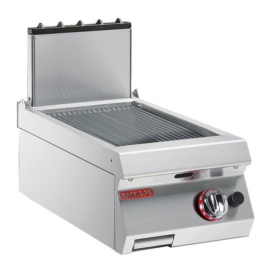
(see foods in direct contact with the plate in the profession- figure). al catering sector. 0G0FT1G 0G0FT2G Smooth (iron) Ribbed (iron) 0G0FT4G... - Page 6 Main Parts A)Cooking plate: produced in a variety of shapes and materials to meet the different requirements. B)Fume exhaust vent (Type A): for removal of the fumes generated by the burner. C)Drain plug: for draining cooking residues into the drip tray.
-
Page 7: Safety
SAFETY AND INFORMATION SIGNS The illustration shows the position of the signs provid- A)Burn hazard: watch out for hot surfaces. B)General hazard: read the manual carefully before carrying out any procedure. C)General hazard: describes the precautions to be adopted during installation and commissioning. D)Nameplate with manufacturer and appliance data. -
Page 8: Use And Operation
tions, use only food-approved detergents, and never the gas supply lines disconnected. use flammable products or products which contain In case of lengthy downtimes, as well as disconnect- substances harmful to health. Clean only when rea- ing all supply lines it is also essential to clean all inter- sonably necessary and at the end of each session of nal and external parts of the appliance and the use. - Page 9 SWITCHING THE BURNER ON AND OFF Lighting N.B.: the first time the griddle is switched on, wash the plate to remove the protective grease and any dirt, then switch on the appliance and preheat it for about 2 hours at the temperature of 195°C.
-
Page 10: Servicing
FITTING THE SPLASH GUARD FRAME To carry out this operation, proceed as follows. 1 - Fit the rear frame (A) into the groove provided. 2 - Fit the side frames (B) by inserting the pins into the slots in the rear frame. N.B.: to clean, remove the splash guard frame and put it in a dishwasher. - Page 11 Every 100 working hours have skilled, authorised a check on the efficiency of the flues, cleaning them personnel carry out the following operations: if necessary; a check on the gas pressure and system tightness; check that the safety thermostat is working correct- a check on the efficiency of the safety thermocouple;...
-
Page 12: Fault
CHECKING GAS PRESSURE To carry out this operation, proceed as follows. 1 - Turn off the gas supply tap. 2 - Pull off the knob (A). 3 - Undo the screws (B) and remove the control panel (C). 4 - Undo the screw (D) of the pressure connection. -
Page 13: Handling And Installation
HANDLING AND INSTALLATION RECOMMENDATIONS FOR HANDLING AND INSTALLATION Important When handling and installing the appliance If necessary, the person authorised to carry comply with the information provided by out these operations must organise a "safe- the constructor directly on the packaging, ty plan"... - Page 14 INSTALLATION OF THE APPLIANCE All installation stages must be considered right from production of the general layout. Before starting these stages, as well as deciding the place of instal- lation, if necessary, the person authorised to carry out these operations must organise a "safety plan" to protect the people directly involved, and he must also ensure strict compliance with all legal require- ments, especially those relating to mobile work-...
- Page 15 Always install a quick-closing ON/OFF valve (A) (not supplied). For Natural gas equipment, fit the gas regulator (B) supplied with the appliance to gas con- nection. Caution - warning For Natural gas equipment this appliance must be fitted with a Bromic Oara 98 gas re- gulator (AGA Approval N°5862) supplied with the appliance.Do not use any other gas regulator.Ensure regulator is fitted with re-...
-
Page 16: Adjustments
ADJUSTMENTS RECOMMENDATIONS FOR ADJUSTMENTS Important Before making any type of adjustment, acti- In particular, turn off the gas supply tap and vate all the safety devices provided and de- prevent access to all devices which might cide whether staff at work and those in the cause unexpected health and safety haz- vicinity should be informed. -
Page 17: Replacing Parts
REPLACING PARTS RECOMMENDATIONS FOR REPLACING PARTS Before carrying out any replacement procedure, acti- The manufacturer declines all responsibly for injury or vate all the safety devices provided and decide damage to components due to the use of non original whether staff at work and those in the vicinity should parts, or extraordinary work on the appliance which be informed. - Page 18 REPLACEMENT OF THE PILOT LIGHT INJECTOR To carry out this operation, proceed as follows. 1 - Turn off the gas supply tap. 2 - Pull off the knobs (A). 3 - Undo the screws (B) and remove the control panel (C).
-
Page 19: Annexes
- ANNEXES - Burner Total Gas consumption Model 22 MJ/h ULPG 0G0FT1G 0G0FT2G N. 1 22 MJ/h 22 MJ/h 0G0FT4G 0G0FT5G - CONNECTION CARD - IDM-39603310100.tif N.G.C. (2) T.G.C. (3) Pilot Flame Bushing TPP (1) Supply pressure G.C. Ø (2.1) G.C.
Need help?
Do you have a question about the 0G0FT1G and is the answer not in the manual?
Questions and answers