
Related Manuals for Huawei UPS5000-H-1200 kVA


Summary of Contents for Huawei UPS5000-H-1200 kVA
- Page 1 UPS5000-H-(1200 kVA-1600 kVA) User Manual (100 kVA Power Modules) Issue Date 2021-04-22 HUAWEI TECHNOLOGIES CO., LTD.
- Page 2 Notice The purchased products, services and features are stipulated by the contract made between Huawei and the customer. All or part of the products, services and features described in this document may not be within the purchase scope or the usage scope. Unless otherwise specified in the contract, all statements, information, and recommendations in this document are provided "AS IS"...
-
Page 3: About This Document
Indicates a hazard with a high level of risk which, if not avoided, will result in death or serious injury. Indicates a hazard with a medium level of risk which, if not avoided, could result in death or serious injury. Issue 03 (2021-04-22) Copyright © Huawei Technologies Co., Ltd. - Page 4 Issue 03 (2021-04-22) Added the 1600 kVA model. Issue 02 (2020-10-15) ● Updated some monitoring and technical specifications. ● Added the appendix Lifting Trolley. Issue 01 (2020-07-15) This issue is the first release. Issue 03 (2021-04-22) Copyright © Huawei Technologies Co., Ltd.
-
Page 5: Table Of Contents
4 Component Description....................... 31 4.1 Power Module..................................31 4.2 Bypass Module..................................32 4.3 Control Module..................................34 4.3.1 Overview....................................34 4.3.2 ECM......................................35 4.3.3 Dry Contact Card................................36 4.3.4 Monitoring Interface Card.............................. 39 Issue 03 (2021-04-22) Copyright © Huawei Technologies Co., Ltd. - Page 6 6.2.6.2 Installing Cables................................108 6.2.7 Installing the UPS + Bottom Cabling Cabinet + Top Air-flow Cabinet............109 6.2.7.1 Installing Cabinets............................... 109 6.2.7.2 Installing Cables................................116 6.3 Single UPS Installation (1600 kVA)..........................117 Issue 03 (2021-04-22) Copyright © Huawei Technologies Co., Ltd.
- Page 7 7.6.2.2 Performing a Capacity Test............................172 7.6.2.3 Performing a Group Capacity Test......................... 173 7.6.3 Downloading the Test Data............................174 7.7 Transferring to Maintenance Bypass Mode....................... 175 7.8 Transferring from Maintenance Bypass Mode to Inverter Mode...............176 Issue 03 (2021-04-22) Copyright © Huawei Technologies Co., Ltd.
- Page 8 11 Technical Specifications....................204 A (Optional) TN-C System Application................213 B Lifting Trolley........................214 C Installing Optional Rear Copper Bar Protection Components.........216 D Replacing a Fan in the Top Air-flow Cabinet...............218 E Acronyms and Abbreviations....................221 Issue 03 (2021-04-22) Copyright © Huawei Technologies Co., Ltd.
-
Page 9: Safety Information
The "NOTICE", "CAUTION", "WARNING", and "DANGER" statements in this document do not cover all the safety instructions. They are only supplements to the safety instructions. Huawei will not be liable for any consequence caused by the violation of general safety requirements or design, production, and usage safety standards. - Page 10 ● Keep irrelevant people away from the equipment. Only operators are allowed to access the equipment. ● Use insulated tools or tools with insulated handles, as shown in the following figure. Issue 03 (2021-04-22) Copyright © Huawei Technologies Co., Ltd.
- Page 11 Do not change the structure or installation sequence of equipment without permission. ● Do not touch a running fan with your fingers, components, screws, tools, or boards before the fan is powered off or stops running. Issue 03 (2021-04-22) Copyright © Huawei Technologies Co., Ltd.
-
Page 12: Personnel Requirements
Do not power on the equipment before it is installed or confirmed by professionals. 1.2 Personnel Requirements ● Personnel who plan to install or maintain Huawei equipment must receive thorough training, understand all necessary safety precautions, and be able to correctly perform all operations. ●... - Page 13 0°C. Handle cables with caution, especially at a low temperature. – Cables stored at subzero temperatures must be stored at room temperature for at least 24 hours before they are laid out. Issue 03 (2021-04-22) Copyright © Huawei Technologies Co., Ltd.
-
Page 14: Installation Environment Requirements
Install the equipment in an area far away from liquids. Do not install it under areas prone to condensation, such as under water pipes and air exhaust vents, or areas prone to water leakage, such as air conditioner vents, ventilation Issue 03 (2021-04-22) Copyright © Huawei Technologies Co., Ltd. - Page 15 Any violations must be promptly pointed out by the site manager or safety supervisor and the involved personnel should be prompted for correction. Personnel who fail to stop violations will be forbidden from working. Issue 03 (2021-04-22) Copyright © Huawei Technologies Co., Ltd.
-
Page 16: Mechanical Safety
Ensure that the wider end of the ladder is at the bottom, or protective measures have been taken at the bottom to prevent the ladder from sliding. Issue 03 (2021-04-22) Copyright © Huawei Technologies Co., Ltd. - Page 17 D ANGER When removing a heavy or unstable component from a cabinet, be aware of unstable or heavy objects on the cabinet. ● Be cautious to avoid injury when moving heavy objects. Issue 03 (2021-04-22) Copyright © Huawei Technologies Co., Ltd.
-
Page 18: Device Running Safety
The UPS operating environment must meet the requirements for the climate indicator, mechanically active substance indicator, and chemically active substance indicator in ETSI EN 300 019-1 class 3.6. Issue 03 (2021-04-22) Copyright © Huawei Technologies Co., Ltd. - Page 19 UPS is connected to a backfeed protection card. Disconnect the backfeed protection card from the UPS before operating the UPS. Do not use the UPS in the following places: Issue 03 (2021-04-22) Copyright © Huawei Technologies Co., Ltd.
-
Page 20: Battery Safety
● Dispose of waste batteries in accordance with local laws and regulations. Do not dispose of batteries as household waste. If a battery is disposed of improperly, it may explode. Issue 03 (2021-04-22) Copyright © Huawei Technologies Co., Ltd. - Page 21 NO TICE To ensure battery safety and battery management accuracy, use batteries provided with the UPS by Huawei. Huawei is not responsible for any battery faults caused by batteries not provided by Huawei. Battery Installation Before installing batteries, observe the following safety precautions: ●...
- Page 22 Use batteries within the allowed temperature range; otherwise, the battery performance and safety will be compromised. ● Do not throw a lithium battery in fire. ● When maintenance is complete, return the waste lithium battery to the maintenance office. Issue 03 (2021-04-22) Copyright © Huawei Technologies Co., Ltd.
-
Page 23: Others
UPS output voltage level or frequency. Doing so may affect the power supply to equipment. ● Exercise caution when setting battery parameters. Incorrect settings will affect the power supply and battery lifespan. Issue 03 (2021-04-22) Copyright © Huawei Technologies Co., Ltd. -
Page 24: Product Overview
2 Product Overview Product Overview 2.1 Positioning The UPS5000-H is a high-end modular UPS launched by Huawei. It adopts online double conversion and modular redundancy design for components. Based on the digital signal processing (DSP) technology, the UPS5000-H features high efficiency and power density. -
Page 25: Application Scenarios
Table 2-1 Typical UPS configurations Configuration Application Scenario Description Single UPS Supplies power to common loads. Issue 03 (2021-04-22) Copyright © Huawei Technologies Co., Ltd. - Page 26 If loads are light, the UPS provides redundant capacity even if only a single UPS is operating, which ensures high reliability. Figure 2-1 Typical application scenario of a single UPS Issue 03 (2021-04-22) Copyright © Huawei Technologies Co., Ltd.
- Page 27 You can install an optional static transfer switch (STS) to start a bus synchronization controller (BSC) provided in standard configuration. The UPS systems work in inverter mode or bypass mode. Issue 03 (2021-04-22) Copyright © Huawei Technologies Co., Ltd.
-
Page 28: Working Principle
The power module consists of a rectifier, inverter, and DC/DC converter. The UPS converts inputs into pure high-quality sine wave outputs by using the high-frequency switching technology. Figure 2-4 Conceptual diagram 2.5 Working Modes 2.5.1 Normal Mode Issue 03 (2021-04-22) Copyright © Huawei Technologies Co., Ltd. -
Page 29: Bypass Mode
The bypass power supply is not protected by the UPS and therefore is prone to the mains outage, abnormal AC voltage waveform, or abnormal frequency. Figure 2-6 UPS conceptual diagram in bypass mode 2.5.3 Battery Mode Issue 03 (2021-04-22) Copyright © Huawei Technologies Co., Ltd. -
Page 30: Eco Mode
Figure 2-8 UPS conceptual diagram in ECO mode NO TE Manual startup is required to ensure that the inverter is in standby state and the power flow has reached the inverter. Issue 03 (2021-04-22) Copyright © Huawei Technologies Co., Ltd. -
Page 31: Source-Share Mode
UPS transfers to source-share mode. In this case, the power module obtains energy from both the mains and batteries, and the energy is converted into AC outputs by the inverter. Figure 2-9 Conceptual diagram in source-share mode Issue 03 (2021-04-22) Copyright © Huawei Technologies Co., Ltd. -
Page 32: Product Description
(compatible with 900 kVA, 1000 kVA, and 1100 kVA) ● 1600K: output capacity of 1600 kVA in full configuration (compatible with 1300 kVA, 1400 kVA, 1500 kVA) Switch N: no switch configuration Issue 03 (2021-04-22) Copyright © Huawei Technologies Co., Ltd. -
Page 33: Cabinet Description
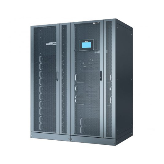
● If the system is configured with a bottom cabling cabinet, cables can be routed in and out from the bottom. 3.2 Cabinet Description Figure 3-2 UPS (1200 kVA) Issue 03 (2021-04-22) Copyright © Huawei Technologies Co., Ltd. - Page 34 (7) Bypass control module (8) Bypass modules Figure 3-4 UPS + top cabling component (1200 kVA) (1) Top cabling component (optional, including (2) UPS the top frame and transfer copper bar) Issue 03 (2021-04-22) Copyright © Huawei Technologies Co., Ltd.
- Page 35 (2) Transfer copper bar for (3) UPS (optional, including the bottom cabling (optional) enclosure frame) Figure 3-6 UPS + top air-flow cabinet (1200 kVA) (1) Top air-flow cabinet (optional) (2) UPS Issue 03 (2021-04-22) Copyright © Huawei Technologies Co., Ltd.
- Page 36 Figure 3-8 UPS + bottom cabling cabinet + top air-flow cabinet (1200 kVA) (1) Top air-flow cabinet (optional) (2) Bottom cabling cabinet (optional, including the enclosure frame) (3) Transfer copper bar for bottom cabling (4) UPS (optional) Issue 03 (2021-04-22) Copyright © Huawei Technologies Co., Ltd.
- Page 37 Figure 3-10 UPS structure with the door open (1600 kVA) (1) SPDs and SPD switches (2) Power modules (3) Surge protection boxes (4) Filler panel (for an optional (5) Control module (6) Filler panel (optional) ECM extended subrack) Issue 03 (2021-04-22) Copyright © Huawei Technologies Co., Ltd.
- Page 38 (1) Bottom cabling cabinet (2) Power cabinet 1 (3) Transfer copper bar for (optional, including the top bottom cabling (optional) frame and transfer copper bar) (4) Power cabinet 2 (5) Bypass cabinet Issue 03 (2021-04-22) Copyright © Huawei Technologies Co., Ltd.
-
Page 39: Component Description
(blinking at 0.5 Hz, on for 1s and off for 1s). intervals ● The inverter is not started (blinking at 0.2 Hz, on for 2.5s and off for 2.5s). Issue 03 (2021-04-22) Copyright © Huawei Technologies Co., Ltd. -
Page 40: Bypass Module
The power module overload times out. ● Both active and standby energy control modules (ECMs) in the system are abnormal. ● The system runs abnormally. ● The UPS is transferred to bypass mode manually. Issue 03 (2021-04-22) Copyright © Huawei Technologies Co., Ltd. - Page 41 Fault Steady on A critical alarm is generated for the indicator bypass. There is no critical alarm for the bypass, or the software is being upgraded. Issue 03 (2021-04-22) Copyright © Huawei Technologies Co., Ltd.
-
Page 42: Control Module
(13) RS485 port (14) FE port (15) COM2 port (16) COM1 port (17) Battery (18) Optional card temperature sensor subrack cover port NO TE Ports are protected by a security mechanism. Issue 03 (2021-04-22) Copyright © Huawei Technologies Co., Ltd. -
Page 43: Ecm
BSC cables are hot-swappable. NO TE No parallel cable is required for a single UPS. Table 4-6 Indicator description Indicator Color Status Description NORMAL Green Steady on This ECM is the active ECM. Issue 03 (2021-04-22) Copyright © Huawei Technologies Co., Ltd. -
Page 44: Dry Contact Card
The dry contact card allows the UPS to detect and manage the switch status of the battery system (including the external battery switch) and implement remote emergency power off (EPO). The dry contact card is 0.5 U high and hot- swappable. Issue 03 (2021-04-22) Copyright © Huawei Technologies Co., Ltd. - Page 45 (DG) mode mode ● Open: non-DG Port for signal ground mode BCB_OL Port for monitoring the ● Grounded: BCB Grounde battery circuit breaker (BCB) box connected ● Disconnected: BCB box not connected Issue 03 (2021-04-22) Copyright © Huawei Technologies Co., Ltd.
- Page 46 Port for signal ground is ON. STATUS_0V ● Open: The bypass input circuit breaker is OFF. Port for monitoring the ● Closed: The Closed input AC SPD input AC SPD is normal. Issue 03 (2021-04-22) Copyright © Huawei Technologies Co., Ltd.
-
Page 47: Monitoring Interface Card
● When multiple UPSs are connected in parallel, all dry contact signals to be used need to connect to each UPS. Figure 4-7 Monitoring interface card Issue 03 (2021-04-22) Copyright © Huawei Technologies Co., Ltd. - Page 48 Network port ● Supported protocols: Modbus-TCP, HTTPS, and SNMP ● Connects to the network port on a PC. ● Network port for connecting to the web service and for SNMP networking Issue 03 (2021-04-22) Copyright © Huawei Technologies Co., Ltd.
- Page 49 ● RS485 cables and FE cables must be shielded cables. Figure 4-8 Figure 4-9 are recommended wiring methods for DO ports. Figure 4-8 Wiring method 1 Figure 4-9 Wiring method 2 Issue 03 (2021-04-22) Copyright © Huawei Technologies Co., Ltd.
- Page 50 Figure 4-10 COM1 port pins Table 4-9 Pin definitions for the COM1 port Description RS485– RS485+ 12V_PORT Figure 4-11 COM2 port pins Table 4-10 Pin definitions for the COM2 port Description RS485+ RS485– Issue 03 (2021-04-22) Copyright © Huawei Technologies Co., Ltd.
- Page 51 User Manual (100 kVA Power Modules) 4 Component Description Description RS485+ RS485– CANH0 CANL0 Figure 4-12 RS485 port pins Table 4-11 Pin definitions for the RS485 port Description RS485_T+ RS485_T– RS485_R+ RS485_R– Issue 03 (2021-04-22) Copyright © Huawei Technologies Co., Ltd.
-
Page 52: Intelligent Detection Card
Indicates the CPU power status of the intelligent detection card. The indicator is steady on after the card is powered on and does not need to be controlled by the CPU. Issue 03 (2021-04-22) Copyright © Huawei Technologies Co., Ltd. - Page 53 50 m, the cross-sectional area must be 0.5–1.5 mm ● RS485 cables and FE cables must be shielded cables. Figure 4-14 COM_OUT port pins Table 4-14 Pin definitions for the COM_OUT port Description RS485+ RS485– RS485+ RS485– CANH CANL Issue 03 (2021-04-22) Copyright © Huawei Technologies Co., Ltd.
-
Page 54: Surge Protection Box
FE4_RX+ FE4_RX- 4.5 Surge Protection Box The surge protection box is used to improve the surge protection capability for the UPS. It applies to a three-phase four-wire + PE power system. Issue 03 (2021-04-22) Copyright © Huawei Technologies Co., Ltd. -
Page 55: Mdu
A minor alarm has been generated, and the buzzer buzzes intermittently at 2 Hz. Green The UPS is running properly or a warning has been generated. The MDU is powered off. Issue 03 (2021-04-22) Copyright © Huawei Technologies Co., Ltd. - Page 56 View or obtain UPS running information during inspection. NOTE Only Huawei service engineers or authorized service engineers are allowed to use the WiFi module. To ensure security, remove the WiFi module immediately after use. ● Insert a USB flash drive to import and export configuration files, export run logs, and upgrade software.
-
Page 57: Optional Components
Parallel cable 5 m/10 m/15 m Connects UPSs in parallel. Top air-flow cabinet Applies to the top airflow scenario. Currently, only the 1200 kVA model is supported. Issue 03 (2021-04-22) Copyright © Huawei Technologies Co., Ltd. -
Page 58: Dry Contact Extended Card
NO TE The ECM extended subrack does not support onsite installation. If you require this optional component, inform Huawei when you purchase the UPS so that Huawei can install the subrack before delivery. 5.2 Dry Contact Extended Card The dry contact extended card provides five groups of electric relay output ports for dry contact signals and five groups of signal input ports to implement various alarm and control functions as required. - Page 59 Door alarm and Water alarm. The default value is None. ● DI ports detect input dry contact signals which DI_3 are passive signals. DI_4 DI_5 The following wiring methods are recommended for DO ports. Issue 03 (2021-04-22) Copyright © Huawei Technologies Co., Ltd.
-
Page 60: Backfeed Protection Card
When energy backfeed occurs, the backfeed protection card sends signals to trigger alarm signals or quickly disconnect the feedback loop. The card is hot swappable. Figure 5-4 Appearance Figure 5-5 Ports on the backfeed protection card Issue 03 (2021-04-22) Copyright © Huawei Technologies Co., Ltd. -
Page 61: Bcb Box
RSV_NO Reserved (reserved) RSV_COM RSV_NC 5.4 BCB Box The BCB box controls the connection between battery strings and the UPS, and supports overload protection, short circuit protection, and remote trip control. Issue 03 (2021-04-22) Copyright © Huawei Technologies Co., Ltd. -
Page 62: Ambient T/H Sensor
32 to 44. A DIP switch has six binary toggle switches. The bit on the leftmost is the most significant bit, and the bit on the rightmost is the least significant bit. Bit 1 indicates ON, and bit 0 indicates OFF. Issue 03 (2021-04-22) Copyright © Huawei Technologies Co., Ltd. - Page 63 Figure 5-8 DIP switch on the ambient T/H sensor (1) DIP switch Table 5-4 DIP switch address mapping When the ambient T/H sensor is used as a battery temperature sensor, the DIP switch address ranges from 16 to 28. Issue 03 (2021-04-22) Copyright © Huawei Technologies Co., Ltd.
-
Page 64: Top Air-Flow Cabinet
Figure 5-9 Appearance (1) Fan power switch (2) Cover stopper (3) Fans Table 5-6 Specifications Item Specifications Dimensions (H x W x 2000 mm x 400 mm x 1000 mm Weight 150 kg Issue 03 (2021-04-22) Copyright © Huawei Technologies Co., Ltd. -
Page 65: Bottom Cabling Cabinet
Figure 5-10 Cabinet 5.8 Rear Copper Bar Protection Component Protects copper bars at the rear of the cabinet. Figure 5-11 Appearance 5.9 Top Cabling Component Applies to the top cabling scenario. Issue 03 (2021-04-22) Copyright © Huawei Technologies Co., Ltd. - Page 66 UPS5000-H-(1200 kVA-1600 kVA) User Manual (100 kVA Power Modules) 5 Optional Components Figure 5-12 Copper bar assembly (1200 kVA) Figure 5-13 Top frame (1200 kVA) Figure 5-14 Copper bar assembly (1600 kVA) Issue 03 (2021-04-22) Copyright © Huawei Technologies Co., Ltd.
- Page 67 UPS5000-H-(1200 kVA-1600 kVA) User Manual (100 kVA Power Modules) 5 Optional Components Figure 5-15 Top frame (1600 kVA) Issue 03 (2021-04-22) Copyright © Huawei Technologies Co., Ltd.
-
Page 68: Installation
Reserve a clearance of at least 500 mm from the rear of the cabinet for ventilation. – Reserve a clearance of at least 800 mm if you need to perform operations at the rear of the cabinet. Issue 03 (2021-04-22) Copyright © Huawei Technologies Co., Ltd. - Page 69 If the top air-flow cabinet is configured, no space is reserved at the rear. Figure 6-1 UPS installation clearances (1200 kVA) Figure 6-2 UPS + top cabling component installation clearances (1200 kVA) Issue 03 (2021-04-22) Copyright © Huawei Technologies Co., Ltd.
- Page 70 UPS5000-H-(1200 kVA-1600 kVA) User Manual (100 kVA Power Modules) 6 Installation Figure 6-3 UPS + bottom cabling cabinet installation clearances (1200 kVA) Figure 6-4 UPS + top air-flow cabinet installation clearances (1200 kVA) Issue 03 (2021-04-22) Copyright © Huawei Technologies Co., Ltd.
- Page 71 6 Installation Figure 6-5 UPS + top cabling component + top air-flow cabinet installation clearances (1200 kVA) Figure 6-6 UPS + bottom cabling cabinet + top air-flow cabinet installation clearances (1200 kVA) Issue 03 (2021-04-22) Copyright © Huawei Technologies Co., Ltd.
- Page 72 UPS5000-H-(1200 kVA-1600 kVA) User Manual (100 kVA Power Modules) 6 Installation Figure 6-7 UPS installation clearances (1600 kVA) Figure 6-8 UPS + top cabling component installation clearances (1600 kVA) Issue 03 (2021-04-22) Copyright © Huawei Technologies Co., Ltd.
-
Page 73: Tools And Instruments
Table 6-1 Tools and meters Tools and Meters Electric pallet Manual pallet Ladder Rubber mallet truck truck Hammer drill and Hand-held Alloy hole saw Heat gun drill bit Φ16 electric drill Issue 03 (2021-04-22) Copyright © Huawei Technologies Co., Ltd. - Page 74 Level instrument Polyvinyl chloride Cotton cloth Label Electrician's knife (PVC) insulation tape Electrostatic Protective gloves Insulated gloves Insulation discharge (ESD) protective shoes gloves Torque Cable cutter Brush Flat-head screwdriver screwdriver (2–5 mm) Issue 03 (2021-04-22) Copyright © Huawei Technologies Co., Ltd.
-
Page 75: Preparing Power Cables
If the top cabling component and bottom cabling cabinet are not configured, prepare wiring copper bars for mains input, bypass input, and output based on the following drawings and current requirements. Issue 03 (2021-04-22) Copyright © Huawei Technologies Co., Ltd. - Page 76 Copper bars must not be exposed.) (2) Space for the dense busway Issue 03 (2021-04-22) Copyright © Huawei Technologies Co., Ltd.
- Page 77 Figure 6-12 Front view of the distance between copper bars on the top (1200 kVA; unit: mm) Figure 6-13 Front view of the distance between copper bars on the top (1600 kVA; unit: mm) Issue 03 (2021-04-22) Copyright © Huawei Technologies Co., Ltd.
- Page 78 Figure 6-14 Input and output copper bar specifications (1200 kVA, unit: mm) Figure 6-15 Input and output copper bar specifications (1600 kVA, unit: mm) Figure 6-16 Battery copper bar wiring holes (1200 kVA, unit: mm) Issue 03 (2021-04-22) Copyright © Huawei Technologies Co., Ltd.
- Page 79 6 x 240 6 x 240 cross- sectional 5 x 240 5 x 240 6 x 240 6 x 240 area 5 x 240 5 x 240 6 x 240 6 x 240 Issue 03 (2021-04-22) Copyright © Huawei Technologies Co., Ltd.
- Page 80 (mm Table 6-3 Recommended power cable cross-sectional areas (1300–1600 kVA) Item 1300 kVA 1400 kVA 1500 kVA 1600 kVA Mains input Mains input 2415 2601 2787 2972 current (A) Issue 03 (2021-04-22) Copyright © Huawei Technologies Co., Ltd.
- Page 81 2 x 240 2 x 240 2 x 240 2 x 240 area Battery Nominal battery 2673 2879 3084 3290 input discharge current (SmartLi) Maximum battery 3355 3614 3871 4130 discharge current Issue 03 (2021-04-22) Copyright © Huawei Technologies Co., Ltd.
- Page 82 – Conductor material: 90°C flexible copper cable – It is recommended that AC power cables be no longer than 30 meters and DC power cables be no longer than 50 meters. Issue 03 (2021-04-22) Copyright © Huawei Technologies Co., Ltd.
- Page 83 3200 3200 3200 circuit A/3P A/3P A/3P A/3P A/3P A/3P A/3P A/3P breaker a: recommended model when the short-circuit current where the circuit breaker is located is less than 65 kA Issue 03 (2021-04-22) Copyright © Huawei Technologies Co., Ltd.
-
Page 84: Unpacking
Step 2 Remove the UPS outer packing. Step 3 After confirming that the UPS is intact, remove the bolts that secure the UPS to the pallet and remove the UPS from the pallet. Figure 6-18 Unpacking ----End Issue 03 (2021-04-22) Copyright © Huawei Technologies Co., Ltd. -
Page 85: Single Ups Installation (1200 Kva)
Figure 6-19 Preparing a cable terminal outside the cabinet NO TE Choose an appropriate cabling route based on the actual situation. The figure is for reference only. Issue 03 (2021-04-22) Copyright © Huawei Technologies Co., Ltd. -
Page 86: Installing The Ups
Partially tighten the expansion bolt and vertically insert it into the hole. Knock the expansion bolt using a rubber mallet until the expansion sleeve is fully inserted into the hole. Partially tighten the expansion bolt. Issue 03 (2021-04-22) Copyright © Huawei Technologies Co., Ltd. - Page 87 (2) Spring washer (3) Flat washer (4) Expansion sleeve (5) Expansion nut (6) Concrete floor Step 3 Secure the cabinets. Figure 6-22 Securing the cabinets Step 4 Install anchor baffle plates. Issue 03 (2021-04-22) Copyright © Huawei Technologies Co., Ltd.
- Page 88 ----End Installation on Channel Steel NO TICE ● Huawei does not provide channel steel or expansion bolts for securing channel steel. Customers need to purchase them by themselves. ● Ensure that the surface of channel steel is level. ● The procedure for installation on channel steel is similar to that for installation on the floor except the following steps: ●...
-
Page 89: Installing Cables
Step 2 (Optional) Remove the copper bars between the mains input and bypass input. NO TICE Perform this step only when the mains input and bypass input use different power sources. Issue 03 (2021-04-22) Copyright © Huawei Technologies Co., Ltd. - Page 90 The number and colors of cables are for reference only. The figure uses the cable connection between the UPS and the SmartLi as an example. Connect battery cables to each SmartLi. Issue 03 (2021-04-22) Copyright © Huawei Technologies Co., Ltd.
- Page 91 Step 4 Install top supports and covers of the battery terminal protective covers. Figure 6-30 Installing top supports and covers Step 5 Install input and output busbars. Issue 03 (2021-04-22) Copyright © Huawei Technologies Co., Ltd.
- Page 92 The figure uses the cable connection between the UPS and the SmartLi as an example. Figure 6-31 Installing signal cables between the UPS and the SmartLi (1) Monitoring interface unit in the master SmartLi cabinet ----End Issue 03 (2021-04-22) Copyright © Huawei Technologies Co., Ltd.
-
Page 93: Installing The Ups + Top Cabling Component
Procedure Step 1 Install conversion copper bars from right to left and remove the left and right connecting kits from the top of the cabinets. Figure 6-33 Installing conversion copper bars Issue 03 (2021-04-22) Copyright © Huawei Technologies Co., Ltd. - Page 94 Remove the copper bars. Reinstall the SPD. NO TICE The mains and bypass copper bars are heavy. To prevent personal injury or device damage, arrange for two persons to work together. Issue 03 (2021-04-22) Copyright © Huawei Technologies Co., Ltd.
- Page 95 The number and colors of cables are for reference only. The figure uses the cable connection between the UPS and the SmartLi as an example. Connect battery cables to each SmartLi. Issue 03 (2021-04-22) Copyright © Huawei Technologies Co., Ltd.
- Page 96 (1) Connect the ground cable of the battery string or its BBB box to the battery PE of the UPS or the ground bar in the equipment room based on the site survey. Step 5 Install top frames. Figure 6-39 Installing top frames Step 6 Install top covers. Issue 03 (2021-04-22) Copyright © Huawei Technologies Co., Ltd.
- Page 97 SmartLi cabinet to the COM2 port on the monitoring interface card. NO TE The figure uses the cable connection between the UPS and the SmartLi as an example. Issue 03 (2021-04-22) Copyright © Huawei Technologies Co., Ltd.
-
Page 98: Installing The Ups + Bottom Cabling Cabinet
Step 1 Determine the cabinet installation positions on the floor based on the holes in the marking-off template for floor installation. NO TE ● A: mounting holes on the channel steel ● B: mounting holes on the floor Issue 03 (2021-04-22) Copyright © Huawei Technologies Co., Ltd. - Page 99 NO TICE Knock the expansion bolt into the hole until the expansion sleeve completely fits into the hole. The expansion sleeve must be completely buried under the ground to facilitate subsequent installation. Issue 03 (2021-04-22) Copyright © Huawei Technologies Co., Ltd.
- Page 100 Step 3 Remove the UPS cabinet side panels. Step 4 Remove the front panel from the bottom cabling cabinet. Step 5 Combine the bottom cabling cabinet. Figure 6-45 Combining the bottom cabling cabinet Step 6 Secure the cabinets. Issue 03 (2021-04-22) Copyright © Huawei Technologies Co., Ltd.
- Page 101 ----End Installation on Channel Steel NO TICE ● Huawei does not provide channel steel or expansion bolts for securing channel steel. Customers need to purchase them by themselves. ● Ensure that the surface of channel steel is level. ● The procedure for installation on channel steel is similar to that for installation on the floor except the following steps: ●...
-
Page 102: Installing Cables
(5) Bypass input Procedure Step 1 Remove the top covers from the bottom cabling cabinet, some connecting kits, and battery copper bars. Figure 6-50 Removing the covers, connecting kits, and battery copper bars Issue 03 (2021-04-22) Copyright © Huawei Technologies Co., Ltd. - Page 103 Figure 6-52 Installing copper bars Step 4 Install bypass input copper bars (No. 20 to 23) and output copper bars (No. 24 to 27) from right to left. Issue 03 (2021-04-22) Copyright © Huawei Technologies Co., Ltd.
- Page 104 User Manual (100 kVA Power Modules) 6 Installation Figure 6-53 Installing copper bars Step 5 Remove the bottom cabling cover from the bottom cabling cabinet. Step 6 Install equipotential ground cable for cabinets. Issue 03 (2021-04-22) Copyright © Huawei Technologies Co., Ltd.
- Page 105 (1) Ground bar in the equipment room Step 7 Install mains input power cables. Figure 6-55 Installing mains input power cables Step 8 Install bypass input and output power cables. ● Two power sources Issue 03 (2021-04-22) Copyright © Huawei Technologies Co., Ltd.
- Page 106 Remove the copper bars. Reinstall the SPD. NO TICE The mains and bypass copper bars are heavy. To prevent personal injury or device damage, arrange for two persons to work together. Issue 03 (2021-04-22) Copyright © Huawei Technologies Co., Ltd.
- Page 107 Step 9 Install battery cables. Figure 6-59 Installing battery cables Step 10 Install signal cables. Issue 03 (2021-04-22) Copyright © Huawei Technologies Co., Ltd.
- Page 108 Figure 6-60 Installing signal cables between the UPS and the SmartLi (1) Monitoring interface unit in the master SmartLi cabinet Step 11 Install the removed side panels on both sides of the bottom cabling cabinet. Step 12 Install top frames. Issue 03 (2021-04-22) Copyright © Huawei Technologies Co., Ltd.
- Page 109 User Manual (100 kVA Power Modules) 6 Installation Figure 6-61 Installing top frames Step 13 Install the front and rear mounting plates. Figure 6-62 Installing mounting plates Step 14 Install top covers. Issue 03 (2021-04-22) Copyright © Huawei Technologies Co., Ltd.
-
Page 110: Installing The Ups And Top Air-Flow Cabinet
Step 1 Determine the positions for installing cabinets on the mounting surface based on holes in the marking-off template. NO TE ● A: mounting holes on the channel steel ● B: mounting holes on the floor Issue 03 (2021-04-22) Copyright © Huawei Technologies Co., Ltd. - Page 111 Remove the rear door panels from the UPS cabinets. Secure the PC panels to the inner side of the rear door panel from the outer side of the rear door using plastic rivets. Figure 6-65 Securing the PC panels Issue 03 (2021-04-22) Copyright © Huawei Technologies Co., Ltd.
- Page 112 Install anchor baffle plates at the rear of each cabinet. Figure 6-68 Installing anchor baffle plates at the rear of each cabinet (1) UPS cabinets (2) Top air-flow cabinet Step 4 Securing the cabinets Secure the UPS cabinets. Issue 03 (2021-04-22) Copyright © Huawei Technologies Co., Ltd.
- Page 113 Secure the top air-flow cabinet. Remove the power distribution cover and bottom cover from the top air- flow cabinet. Figure 6-70 Removing covers Install connecting kits from the bottom to the middle. Issue 03 (2021-04-22) Copyright © Huawei Technologies Co., Ltd.
- Page 114 Reinstall the power distribution cover and bottom cover. Step 5 Install the removed side panel on the side of the top air-flow cabinet. Step 6 Install the side and front anchor baffle plates. Issue 03 (2021-04-22) Copyright © Huawei Technologies Co., Ltd.
- Page 115 ----End Installation on Channel Steel NO TICE ● Huawei does not provide channel steel or expansion bolts for securing channel steel. Customers need to purchase them by themselves. ● Ensure that the surface of channel steel is level. ● The procedure for installation on channel steel is similar to that for installation on the floor except the following steps: ●...
-
Page 116: Installing Cables
UPS + Top Cabling Component. Install the fan power cables by referring to 6.2.5.2 Installing Cables Installing the UPS+ Top Air-flow Cabinet. Install the top frame for the top air-flow cabinet. Issue 03 (2021-04-22) Copyright © Huawei Technologies Co., Ltd. -
Page 117: Installing The Ups + Bottom Cabling Cabinet + Top Air-Flow Cabinet
Installation on the Floor NO TICE Ensure that the installation floor is flat. Step 1 Determine the positions for installing cabinets on the mounting surface based on holes in the marking-off template. Issue 03 (2021-04-22) Copyright © Huawei Technologies Co., Ltd. - Page 118 Remove the rear door panels from the UPS cabinets. Secure the PC panels to the inner side of the rear door panel from the outer side of the rear door using plastic rivets. Issue 03 (2021-04-22) Copyright © Huawei Technologies Co., Ltd.
- Page 119 Figure 6-81 Installing accessories of the top air-flow cabinet (rear view of the cabinets) Reinstall the door sills and rear door panels. Install anchor baffle plates at the rear of each cabinet. Issue 03 (2021-04-22) Copyright © Huawei Technologies Co., Ltd.
- Page 120 Secure the bottom cabling cabinet. Remove the UPS cabinet side panels. Remove the front panel from the bottom cabling cabinet. Install connecting kits. Figure 6-83 Installing connecting kits Secure the bottom cabling cabinet. Issue 03 (2021-04-22) Copyright © Huawei Technologies Co., Ltd.
- Page 121 Secure the top air-flow cabinet. Remove the power distribution cover and bottom cover from the top air- flow cabinet. Figure 6-85 Removing covers Install connecting kits from the bottom to the middle. Issue 03 (2021-04-22) Copyright © Huawei Technologies Co., Ltd.
- Page 122 Reinstall the power distribution cover and bottom cover. Step 5 Install the removed side panels on the side of the top air-flow cabinet and bottom cabling cabinet. Step 6 Install the side and front anchor baffle plates. Issue 03 (2021-04-22) Copyright © Huawei Technologies Co., Ltd.
- Page 123 ----End Installation on Channel Steel NO TICE ● Huawei does not provide channel steel or expansion bolts for securing channel steel. Customers need to purchase them by themselves. ● Ensure that the surface of channel steel is level. ● The procedure for installation on channel steel is similar to that for installation on the floor except the following steps: ●...
-
Page 124: Installing Cables
Figure 6-90 Power supply to the top air-flow cabinet Step 5 Install the top frame for the top air-flow cabinet. Figure 6-91 Installing the top frame Step 6 Install the mounting plates for the top air-flow cabinet. Issue 03 (2021-04-22) Copyright © Huawei Technologies Co., Ltd. -
Page 125: Single Ups Installation (1600 Kva)
Step 3 Pull the marked cable out of the cabinet, cut the cable from the marked position, strip the cable, and crimp a terminal. Issue 03 (2021-04-22) Copyright © Huawei Technologies Co., Ltd. -
Page 126: Installing The Ups
Step 1 Determine the cabinet installation positions on the floor based on the holes in the marking-off template for floor installation. NO TE ● A: mounting holes on the channel steel ● B: mounting holes on the floor Issue 03 (2021-04-22) Copyright © Huawei Technologies Co., Ltd. - Page 127 NO TICE Knock the expansion bolt into the hole until the expansion sleeve completely fits into the hole. The expansion sleeve must be completely buried under the ground to facilitate subsequent installation. Issue 03 (2021-04-22) Copyright © Huawei Technologies Co., Ltd.
- Page 128 Step 3 Move the cabinets to the mounting holes. Step 4 Remove the covers and take out the parallel copper bars. Figure 6-96 Removing the covers and copper bars Step 5 Combine cabinets. Issue 03 (2021-04-22) Copyright © Huawei Technologies Co., Ltd.
- Page 129 UPS5000-H-(1200 kVA-1600 kVA) User Manual (100 kVA Power Modules) 6 Installation Figure 6-97 Combining cabinets Step 6 Secure the cabinets. Figure 6-98 Securing the cabinets Step 7 Install anchor baffle plates. Issue 03 (2021-04-22) Copyright © Huawei Technologies Co., Ltd.
- Page 130 UPS5000-H-(1200 kVA-1600 kVA) User Manual (100 kVA Power Modules) 6 Installation Figure 6-99 Installing anchor baffle plates Step 8 Install the parallel copper bars. Figure 6-100 Installing copper bars 1 Issue 03 (2021-04-22) Copyright © Huawei Technologies Co., Ltd.
- Page 131 ----End Installation on Channel Steel NO TICE ● Huawei does not provide channel steel or expansion bolts for securing channel steel. Customers need to purchase them by themselves. ● Ensure that the surface of channel steel is level. ● The procedure for installation on channel steel is similar to that for installation on the floor except the following steps: ●...
-
Page 132: Installing Cables
● Perform this step only when the mains input and bypass input use different power sources. ● The mains and bypass copper bars are heavy. To prevent personal injury or device damage, arrange for two persons to work together. Issue 03 (2021-04-22) Copyright © Huawei Technologies Co., Ltd. - Page 133 (1) Connect the ground cable of the battery string or its BBB box to the battery PE of the UPS or the ground bar in the equipment room based on the site survey. Step 4 Install top supports and covers of the battery terminal protective covers. Issue 03 (2021-04-22) Copyright © Huawei Technologies Co., Ltd.
- Page 134 Cable Position of Wiring Terminal Position of Wiring Terminal Cabinet Port Cabinet Port Cable 1 Power cabinet PU XS1 Power cabinet PU XS1 Cable 2 Power cabinet Signal Power cabinet Signal Issue 03 (2021-04-22) Copyright © Huawei Technologies Co., Ltd.
- Page 135 SmartLi cabinet to the COM2 port on the monitoring interface card. NO TE The figure uses the cable connection between the UPS and the SmartLi as an example. Issue 03 (2021-04-22) Copyright © Huawei Technologies Co., Ltd.
-
Page 136: Installing The Ups + Top Cabling Component
Secure the cabinets by referring to 6.3.2.1 Installing Cabinets in Installing the UPS. 6.3.3.2 Installing Cables Context Figure 6-110 Copper bar positions (1) Battery input (2) Battery PE (3) Mains input Issue 03 (2021-04-22) Copyright © Huawei Technologies Co., Ltd. - Page 137 Remove the copper bars between the mains and bypass input wiring terminals. NO TICE The mains and bypass copper bars are heavy. To prevent personal injury or device damage, arrange for two persons to work together. Issue 03 (2021-04-22) Copyright © Huawei Technologies Co., Ltd.
- Page 138 Step 4 Install AC output power cables. Figure 6-115 Installing AC output power cables Issue 03 (2021-04-22) Copyright © Huawei Technologies Co., Ltd.
- Page 139 (1) Connect the ground cable of the battery string or its BBB box to the battery PE of the UPS or the ground bar in the equipment room based on the site survey. Step 6 Install top frames. Figure 6-117 Installing top frames Step 7 Install top covers. Issue 03 (2021-04-22) Copyright © Huawei Technologies Co., Ltd.
- Page 140 Cable Position of Wiring Terminal Position of Wiring Terminal Cabinet Port Cabinet Port Cable 1 Power cabinet PU XS1 Power cabinet PU XS1 Cable 2 Power cabinet Signal Power cabinet Signal Issue 03 (2021-04-22) Copyright © Huawei Technologies Co., Ltd.
- Page 141 SmartLi cabinet to the COM2 port on the monitoring interface card. NO TE The figure uses the cable connection between the UPS and the SmartLi as an example. Issue 03 (2021-04-22) Copyright © Huawei Technologies Co., Ltd.
-
Page 142: Installing The Ups + Bottom Cabling Cabinet
Step 1 Determine the cabinet installation positions on the floor based on the holes in the marking-off template for floor installation. NO TE ● A: mounting holes on the channel steel ● B: mounting holes on the floor Issue 03 (2021-04-22) Copyright © Huawei Technologies Co., Ltd. - Page 143 NO TICE Knock the expansion bolt into the hole until the expansion sleeve completely fits into the hole. The expansion sleeve must be completely buried under the ground to facilitate subsequent installation. Issue 03 (2021-04-22) Copyright © Huawei Technologies Co., Ltd.
- Page 144 (5) Expansion nut (6) Concrete floor Step 3 Combine cabinets. Remove the covers and take out the parallel copper bars. Figure 6-124 Removing the covers and copper bars Combine power cabinet 1. Issue 03 (2021-04-22) Copyright © Huawei Technologies Co., Ltd.
- Page 145 Remove the side panels from power cabinet 1 and the bypass cabinet. Remove the front panel of the bottom cabling cabinet and combine the bottom cabling cabinet. Figure 6-126 Combining the bottom cabling cabinet Step 4 Secure the cabinets. Issue 03 (2021-04-22) Copyright © Huawei Technologies Co., Ltd.
- Page 146 6 Installation Figure 6-127 Securing the cabinets Step 5 Install anchor baffle plates. Figure 6-128 Installing anchor baffle plates Step 6 Install the parallel copper bars. Figure 6-129 Installing copper bars 1 Issue 03 (2021-04-22) Copyright © Huawei Technologies Co., Ltd.
- Page 147 ----End Installation on Channel Steel NO TICE ● Huawei does not provide channel steel or expansion bolts for securing channel steel. Customers need to purchase them by themselves. ● Ensure that the surface of channel steel is level. ● The procedure for installation on channel steel is similar to that for installation on the floor except the following steps: ●...
-
Page 148: Installing Cables
Step 1 Remove the top covers from the bottom cabling cabinet, some connecting kits, and battery copper bars. Figure 6-133 Removing the covers, connecting kits, and battery copper bars Step 2 Install epoxy boards (No. 11 to 14 and 16 to 20). Issue 03 (2021-04-22) Copyright © Huawei Technologies Co., Ltd. - Page 149 Step 3 Install battery copper bars (No. 65 and 67 to 69). Figure 6-135 Installing battery copper bars Step 4 Install mains input copper bars (No. 55 to 59, 61 to 64, and 70) from right to left. Issue 03 (2021-04-22) Copyright © Huawei Technologies Co., Ltd.
- Page 150 6 Installation Figure 6-136 Installing mains input copper bars Step 5 Install bypass input copper bars (No. 40 to 47) and output copper bars (No. 48 to 54) from right to left. Issue 03 (2021-04-22) Copyright © Huawei Technologies Co., Ltd.
- Page 151 Figure 6-137 Installing bypass input and output copper bars Step 6 Install epoxy boards. Figure 6-138 Installing epoxy boards Step 7 Remove the bottom cabling cover from the bottom cabling cabinet. Step 8 Install equipotential ground cable for cabinets. Issue 03 (2021-04-22) Copyright © Huawei Technologies Co., Ltd.
- Page 152 (1) Ground bar in the equipment room Step 9 Install mains input power cables. Figure 6-140 Installing mains input power cables Step 10 Install bypass input and output power cables. ● Two power sources Issue 03 (2021-04-22) Copyright © Huawei Technologies Co., Ltd.
- Page 153 If the mains input and bypass input share a power source, you do not need to remove the copper bar between the mains and bypass input terminals or connect the bypass input power cable. Issue 03 (2021-04-22) Copyright © Huawei Technologies Co., Ltd.
- Page 154 Cable Position of Wiring Terminal Position of Wiring Terminal Cabinet Port Cabinet Port Cable 1 Power cabinet PU XS1 Power cabinet PU XS1 Cable 2 Power cabinet Signal Power cabinet Signal Issue 03 (2021-04-22) Copyright © Huawei Technologies Co., Ltd.
- Page 155 ● The figure uses the cable connection between the UPS and the SmartLi as an example. ● Bind signal cables to the cabinet nearby. Do not bind signal cables and power cables together. Issue 03 (2021-04-22) Copyright © Huawei Technologies Co., Ltd.
- Page 156 Step 14 Install the removed side panels on both sides of the bottom cabling cabinet. Step 15 Install the top frame. Figure 6-146 Installing the top frame Step 16 Install the front and rear mounting plates. Issue 03 (2021-04-22) Copyright © Huawei Technologies Co., Ltd.
-
Page 157: Parallel System Installation
UPS are the same. ● Connect power cables according to port silk screens. Procedure Step 1 Ground each UPS in a parallel system separately, and connect power cables and battery cables. Issue 03 (2021-04-22) Copyright © Huawei Technologies Co., Ltd. - Page 158 Figure 6-149 Conceptual diagram of a 1+1 parallel system A dual-bus parallel system consisting of two parallel subsystems is used as an example. Figure 6-150 Conceptual diagram of a dual-bus parallel system ----End Issue 03 (2021-04-22) Copyright © Huawei Technologies Co., Ltd.
-
Page 159: Connecting A Backfeed Protection Card
Table 6-11 Shunt release selection UPS Voltage System UPS Voltage Level Supply Voltage to Shunt Release Three-phase four-wire 380 V 220 V Three-phase four-wire 400 V 230 V Three-phase four-wire 415 V 240 V Issue 03 (2021-04-22) Copyright © Huawei Technologies Co., Ltd. - Page 160 If a third-party reliable power supply is used, use the power signal whose voltage is less than or equal to 240 V AC and current is less than 4 A. (1200 kVA and 1600 kVA UPSs support this feature.) Issue 03 (2021-04-22) Copyright © Huawei Technologies Co., Ltd.
-
Page 161: Connecting A Remote Epo Switch
6.6 Connecting a Remote EPO Switch NO TICE ● Huawei does not provide the EPO switch or cable. Prepare them by yourself. The recommended cable is 22 AWG. ● Equip the EPO switch with a protective cover to prevent misoperations, and protect the cable with a protective tube. -
Page 162: Verifying The Installation
UPS may be damaged. Table 6-12 Check items and acceptance criteria Item Acceptance Criteria Cabinet installation The cabinets are securely installed and do not tilt due to vibration. Issue 03 (2021-04-22) Copyright © Huawei Technologies Co., Ltd. - Page 163 3. There is no foreign matter around switch terminals. 4. There is no foreign matter on the bottom plates of the cabinets. 5. There is no foreign matter on the rear module subrack. Issue 03 (2021-04-22) Copyright © Huawei Technologies Co., Ltd.
- Page 164 2. After verifying the installation, reinstall all the covers. 3. Do not remove the dustproof cover before power-on to prevent dust from entering the cabinets. Issue 03 (2021-04-22) Copyright © Huawei Technologies Co., Ltd.
-
Page 165: Single Ups Commissioning
Step 1 Turn on the SPD switches 1QFS and 2QFS. Step 2 Turn on the upstream bypass and mains input switches. After the UPS is powered on, initialization begins. The MDU displays the Huawei logo and an initialization progress bar. -
Page 166: Obtaining Startup Password
Service Expert app. Skip this step if the UPS is not powered on for the first time. ● The Service Expert app can be downloaded from HUAWEI AppGallery and can only run on Android. 7.1.2.1 Obtaining Startup Password Procedure Step 1 Download and install the Service Expert app. - Page 167 ● Set all battery parameters correctly based on site requirements. Battery parameter settings are critical to battery maintenance, battery lifespan, and UPS discharge time. Figure 7-1 Settings Wizard Issue 03 (2021-04-22) Copyright © Huawei Technologies Co., Ltd.
-
Page 168: Starting The Inverter
NO TE You can also start the inverter by choosing System Info > Maintenance > Inv. ON. Step 2 On the displayed login screen, select a user name and enter the password. Issue 03 (2021-04-22) Copyright © Huawei Technologies Co., Ltd. -
Page 169: Powering On Loads
UPS. The No battery alarm on the MDU disappears. Step 2 Turn on the downstream output switch to supply power to loads. ----End Issue 03 (2021-04-22) Copyright © Huawei Technologies Co., Ltd. -
Page 170: Optional) Setting Parameters For The Bcb Box
Step 1 On the LCD, choose System Info > Settings > System Settings and set Top outlet cabinet to Enable. ----End 7.1.7 (Optional) Configuring the Bottom Cabling Cabinet Prerequisites The bottom cabling cabinet has been deployed. Issue 03 (2021-04-22) Copyright © Huawei Technologies Co., Ltd. -
Page 171: Optional) Setting The Backfeed Protection Card
You can also choose System Info > Maintenance > Inv. OFF to shut down the inverter. ● Shutting down the inverter on the WebUI Choose Monitoring > UPS System > Running Control, and click Inv. OFF. Issue 03 (2021-04-22) Copyright © Huawei Technologies Co., Ltd. - Page 172 UPS and then switch off the circuit breaker for each battery string. Step 4 Turn off the upstream mains and bypass input switches. ----End Issue 03 (2021-04-22) Copyright © Huawei Technologies Co., Ltd.
-
Page 173: Cold-Starting The Ups Using Batteries
1 Hz or is steady on, press and hold down the BATT START button on the UPS bypass control module for more than 2 seconds. The system automatically enters the battery cold start state. The MDU displays the Huawei logo and an initialization progress bar. -
Page 174: Transferring To Bypass Mode Manually
Step 1 On the LCD, choose System Info > Settings > System Settings and set Working mode to ECO. The information indicating that the UPS works in ECO mode is displayed on the LCD. Step 2 Set the ECO voltage range. Issue 03 (2021-04-22) Copyright © Huawei Technologies Co., Ltd. -
Page 175: Testing Batteries
Figure 7-7 System status in ECO mode ----End 7.6 Testing Batteries 7.6.1 Lead-Acid Battery Test 7.6.1.1 Performing a Forced Equalized Charging Test Context This item allows you to perform equalized charging on batteries forcibly. Issue 03 (2021-04-22) Copyright © Huawei Technologies Co., Ltd. -
Page 176: Performing A Shallow Discharge Test
This item allows you to partially discharge batteries. A shallow discharge test is conducted to test the battery loop reliability and short-time discharge capacity when the batteries have not been discharged for a long time. Issue 03 (2021-04-22) Copyright © Huawei Technologies Co., Ltd. - Page 177 Step 1 On the home screen of the LCD, choose System Info > Maintenance > Battery Maint. Step 2 Tap Start on the right of Shallow Dis. Test to start a shallow discharge test. Figure 7-9 Starting a shallow discharge test Issue 03 (2021-04-22) Copyright © Huawei Technologies Co., Ltd.
-
Page 178: Performing A Capacity Test
Step 1 On the home screen of the LCD, choose System Info > Maintenance > Battery Maint. Step 2 Tap Start on the right of Capacity Test to start a capacity test. Figure 7-10 Starting a capacity test Issue 03 (2021-04-22) Copyright © Huawei Technologies Co., Ltd. -
Page 179: Lithium Battery Test
Manual Shallow Discharge Test On the home screen of the LCD, choose System Info > Maintenance > Battery Maint. Tap Start on the right of Shallow Dis. Test to start a shallow discharge test. Issue 03 (2021-04-22) Copyright © Huawei Technologies Co., Ltd. -
Page 180: Performing A Capacity Test
● The mains, batteries, charger, and discharger are normal. No overload alarm is generated. ● The SmartLi generates no alarms related to lithium batteries. Procedure Step 1 On the home screen of the LCD, choose System Info > Maintenance > Battery Maint. Issue 03 (2021-04-22) Copyright © Huawei Technologies Co., Ltd. -
Page 181: Performing A Group Capacity Test
(When a SmartLi is fully discharged, charge the SmartLi until its SOC reaches 100%, and then discharge the next SmartLi until all SmartLi cabinets are fully discharged.) A deep discharge test is conducted to obtain the battery discharge performance data. Issue 03 (2021-04-22) Copyright © Huawei Technologies Co., Ltd. -
Page 182: Downloading The Test Data
The test is complete when the minimum cell voltage reaches 2.75 V. The test data is obtained from the group capacity test. Save the test data obtained from the latest 36 tests. ----End 7.6.3 Downloading the Test Data Issue 03 (2021-04-22) Copyright © Huawei Technologies Co., Ltd. -
Page 183: Transferring To Maintenance Bypass Mode
LCD. Step 3 Turn on the maintenance bypass switch for external power distribution. Then, the Maint. breaker closed and Bypass mode alarms are displayed on the LCD. ----End Issue 03 (2021-04-22) Copyright © Huawei Technologies Co., Ltd. -
Page 184: Transferring From Maintenance Bypass Mode To Inverter Mode
4-pin terminal on the EPO port of the dry contact card of the bypass unit. Figure 7-16 EPO ports After you press the EPO button, the EPO and No power supplied alarms are displayed on the LCD. 7.10 Clearing the EPO State Issue 03 (2021-04-22) Copyright © Huawei Technologies Co., Ltd. -
Page 185: Exporting Data
The following data can be exported: ● Historical alarms ● Active alarms ● Performance data ● Operation logs ● E-label ● Fault information NO TE This procedure describes how to export historical alarms. Issue 03 (2021-04-22) Copyright © Huawei Technologies Co., Ltd. -
Page 186: Setting Hibernation Mode
Step 1 On the WebUI, choose Monitoring > UPS System > Running Parameter > System Settings, and set Paral sys hibernate to Enable. Step 2 Set Module cycle hiber period(d) to an integer ranging from 1 to 100. The default value is 30. Issue 03 (2021-04-22) Copyright © Huawei Technologies Co., Ltd. - Page 187 UPS5000-H-(1200 kVA-1600 kVA) User Manual (100 kVA Power Modules) 7 Single UPS Commissioning Figure 7-18 System settings NO TE Click Submit after setting parameters on the WebUI. ----End Issue 03 (2021-04-22) Copyright © Huawei Technologies Co., Ltd.
-
Page 188: Parallel System Commissioning
Use a multimeter to measure the impedance between phases A, B, and C of the mains/bypass input and AC output of any UPS. If the measured result is low conducted resistance, check whether the cables to each UPS are short- circuited. Issue 03 (2021-04-22) Copyright © Huawei Technologies Co., Ltd. - Page 189 If the input power is normal, the rectifier starts automatically. The MDU starts and displays the Huawei logo and a progress bar. Wait until the MDU starts properly. NO TE If the input SPD circuit breaker is not switched on, the system can start properly, but an Input surge arrester alarm will be reported.
- Page 190 The system may generate alarms such as Rack quantity mismatch, Insufficient redundant racks, and Inter-rack par. cable alarm. The alarms are automatically cleared 1 minute after you connect all parallel cables. Step 7 Synchronize parallel parameters. Issue 03 (2021-04-22) Copyright © Huawei Technologies Co., Ltd.
- Page 191 Exercise caution when performing operations with power on. There are many electrified parts in the UPS wiring area. It is recommended that the test be performed in the external power distribution area of the UPS. Issue 03 (2021-04-22) Copyright © Huawei Technologies Co., Ltd.
-
Page 192: Shutting Down And Powering Off A Parallel System
Step 2 Turn off the general load switch, external output power distribution switch for each UPS, battery switch, and external input power distribution switch (or the mains and bypass input switches on the external PDC). Issue 03 (2021-04-22) Copyright © Huawei Technologies Co., Ltd. -
Page 193: Performing Epo
Then, the UPS has no output, and the other UPSs continue to work in inverter mode. Step 3 Turn off the output switch of the faulty UPS or the external output power distribution switch. Issue 03 (2021-04-22) Copyright © Huawei Technologies Co., Ltd. -
Page 194: Restoring An Isolated Ups In A Parallel System
Expanding Capacity in Bypass Mode The following operations apply to scenarios where the system works in bypass mode. If the system works in inverter mode, refer to section "Expanding Capacity in Inverter Mode." Issue 03 (2021-04-22) Copyright © Huawei Technologies Co., Ltd. - Page 195 The system may generate alarms such as Rack quantity mismatch, Insufficient redundant racks, and Inter-rack par. cable alarm. The alarms are automatically cleared 1 minute after you connect all parallel cables. Step 5 Set parallel parameters for the new UPS. Issue 03 (2021-04-22) Copyright © Huawei Technologies Co., Ltd.
- Page 196 EPO, ECC800, and dry contact signal cables. ● If two racks are far away from each other, prepare a longer parallel cable. Issue 03 (2021-04-22) Copyright © Huawei Technologies Co., Ltd.
- Page 197 UPS shut down and the UPS transfers to bypass mode. Ensure that the output circuit breaker is OFF. Step 2 Check that the bypass phase sequence of the new UPS and the original UPSs is correct. Issue 03 (2021-04-22) Copyright © Huawei Technologies Co., Ltd.
- Page 198 Table 8-5 System Settings Item Setting Description Single/Parallel Set it to Parallel. Parallel ID Set this The parallel number of each UPS must parameter to be unique. the original maximum parallel ID plus Issue 03 (2021-04-22) Copyright © Huawei Technologies Co., Ltd.
- Page 199 Step 13 Turn on the battery switches for the new UPSs (if there are multiple battery strings, turn on the switch for each battery string and then the general switch between battery strings and the UPSs). Issue 03 (2021-04-22) Copyright © Huawei Technologies Co., Ltd.
-
Page 200: Commissioning A Dual-Bus System
Set the BSC master and slave systems to master and slave modes respectively. Procedure Step 1 Connect BSC cables. Figure 8-2 Parallel cable connections in a dual-bus parallel system Issue 03 (2021-04-22) Copyright © Huawei Technologies Co., Ltd. - Page 201 On the LCD, choose System Info > Settings > System Settings and set BSC master/slave mode to BSC slave system Step 5 Check that the valid phase voltage difference between UPS systems is less than 5 ----End Issue 03 (2021-04-22) Copyright © Huawei Technologies Co., Ltd.
-
Page 202: Routine Maintenance
Customers are not allowed to maintain components behind protective covers that can be removed only using tools. If the components are to be maintained, contact Huawei technical support. ● Only maintenance engineers can maintain power modules and bypass modules. -
Page 203: Monthly Maintenance
Table 9-2 Quarterly maintenance Check Item Expected Result Troubleshooting Cleanliness Wipe the cabinet surface Remove the dust, especially using a white paper and the from the front panel. paper does not turn black. Issue 03 (2021-04-22) Copyright © Huawei Technologies Co., Ltd. -
Page 204: Annual Maintenance
● Replace the circuit breaker through-current cables meet load breaker. capacity requirements. ● Replace the cable. The actual cable through-current capacity is greater than the circuit breaker specifications. 9.2 Lead-Acid Battery Maintenance Issue 03 (2021-04-22) Copyright © Huawei Technologies Co., Ltd. -
Page 205: Precautions For Battery Maintenance
Huawei technical support. 2. The battery terminals are intact. 3. Batteries are free from damage and cracks. 4. Batteries are free from acid leakage. 5. Batteries are not deformed or bulged. Issue 03 (2021-04-22) Copyright © Huawei Technologies Co., Ltd. -
Page 206: Quarterly Maintenance
2. Replace the battery than 3°C. temperature sensor. Battery management The settings of battery Set parameters correctly. parameter settings management parameters meet the requirements in the user manual. Issue 03 (2021-04-22) Copyright © Huawei Technologies Co., Ltd. -
Page 207: Annual Maintenance
1. Locate the cause when an discharge a battery to the exception is identified. undervoltage alarm threshold, 2. If the fault persists, contact to refresh the capacity of the Huawei technical support. battery. Issue 03 (2021-04-22) Copyright © Huawei Technologies Co., Ltd. - Page 208 (A torque wrench is used for checking the torque. After checking that the battery screws meet the requirements, mark the screws for later check.) Issue 03 (2021-04-22) Copyright © Huawei Technologies Co., Ltd.
-
Page 209: Troubleshooting
EOD voltage and 11.3 V/cell. For details about how to rectify common faults, see Table 10-1. If any UPS5000 & SmartLi Alarm Reference or contact unmentioned faults occur, see the Huawei technical support. Issue 03 (2021-04-22) Copyright © Huawei Technologies Co., Ltd. - Page 210 The buzzer buzzes, The bypass Replace the bypass is abnormal. and the fault thyristor is module. indicator is on. damaged. The bypass module Reduce the load, or experiences improve ventilation. overtemperature. Issue 03 (2021-04-22) Copyright © Huawei Technologies Co., Ltd.
- Page 211 UPS5000-H-(1200 kVA-1600 kVA) User Manual (100 kVA Power Modules) 10 Troubleshooting NO TE For details about component replacement and maintenance involved in Troubleshooting UPS5000 & SmartLi Alarm Reference , consult Huawei maintenance engineers. Issue 03 (2021-04-22) Copyright © Huawei Technologies Co., Ltd.
-
Page 212: Technical Specifications
2300 mm x 2000 mm x 1000 mm (with a top cabling component + top air-flow cabinet) 2200 mm x 2800 mm x 1000 mm (with a bottom cabling cabinet + top air-flow cabinet) Issue 03 (2021-04-22) Copyright © Huawei Technologies Co., Ltd. - Page 213 IEC 62040-3. The upper limit of the altitude is 4000 m. Table 11-3 Safety compliance Safety Certification Standard EN 62040-1:2013 IEC 62040-1:2013 EN 62040-1:2013 CQC 3108-2011 GB 7260.1-2008 YD/T 2165-2017 IEC62040-2 Issue 03 (2021-04-22) Copyright © Huawei Technologies Co., Ltd.
- Page 214 30–40°C: not derated at 342–485 V AC, derated from 100% load to 45% load at 342–191 V AC, and derated from 45% load to 35% load at 191–138 V AC Rated frequency 50 Hz/60 Hz Frequency range 40–70 Hz Issue 03 (2021-04-22) Copyright © Huawei Technologies Co., Ltd.
- Page 215 50 Hz/60 Hz±6 Hz (adjustable with a tolerance of 0.5– 6 Hz, ±2 Hz by default) Input mode The mains input and bypass input share a power source (by default) or use different power sources. Issue 03 (2021-04-22) Copyright © Huawei Technologies Co., Ltd.
- Page 216 ● Default float charging voltage: 2.25 V/cell Battery type ● VRLA ● SmartLi NO TICE SmartLi The UPS supports the SmartLi. For details about the parameters, see the User Manual . Issue 03 (2021-04-22) Copyright © Huawei Technologies Co., Ltd.
- Page 217 ● Non-linear load THD < 3% (50–100% load balancing) Power factor Transfer time Uninterruptible transfer: 0 ms; interruptible transfer: ≤ 5 ms (normal) Output voltage Voltage imbalance: ±1% imbalance Phase imbalance: 120±1° Issue 03 (2021-04-22) Copyright © Huawei Technologies Co., Ltd.
- Page 218 1 minute or longer (ambient temperature ≤ 30°C) ● 125% < load ≤ 150%: transfers to bypass mode after 20 seconds or more (ambient temperature > 30°C) Issue 03 (2021-04-22) Copyright © Huawei Technologies Co., Ltd.
- Page 219 1 minute, and the hardware depends on overtemperature protection. ● Load > 1000%: runs for 100 ms Table 11-9 System electrical specifications Item Specifications Parallel system Redundant parallel signals reliability Issue 03 (2021-04-22) Copyright © Huawei Technologies Co., Ltd.
- Page 220 Number of parallel 1200 kVA: A maximum of four UPSs can be connected UPSs in parallel. 1600 kVA: Only a single UPS is supported. Power distribution TN-C, TN-S, TN-C-S, TT system Issue 03 (2021-04-22) Copyright © Huawei Technologies Co., Ltd.
-
Page 221: A (Optional) Tn-C System Application
The figure uses the 1200 kVA UPS as an example. ● Recommended cable cross-sectional area: 240 mm ● Recommended screw: M16 Figure A-1 Short-circuiting the input N and PE (side view of the 1200 kVA UPS) Issue 03 (2021-04-22) Copyright © Huawei Technologies Co., Ltd. -
Page 222: B Lifting Trolley
You can decide whether to choose it based on site requirements. Appearance Figure B-1 Lifting trolley (1) Tabletop (2) Handle (3) Lowering switch (4) Elevating pedal (5) Foot brake Issue 03 (2021-04-22) Copyright © Huawei Technologies Co., Ltd. - Page 223 Step 3 Repeatedly step on the elevating pedal to raise the tabletop to a proper height. Step 4 Lift the lowering switch to slowly lower the tabletop to the required height. ----End Issue 03 (2021-04-22) Copyright © Huawei Technologies Co., Ltd.
-
Page 224: C Installing Optional Rear Copper Bar Protection Components
Procedure Step 1 Remove the UPS rear door panels. Step 2 Install rear optional copper bar protection components. Figure C-1 Installing rear optional copper bar protection components (1200 kVA) Issue 03 (2021-04-22) Copyright © Huawei Technologies Co., Ltd. - Page 225 C Installing Optional Rear Copper Bar Protection User Manual (100 kVA Power Modules) Components Figure C-2 Installing rear optional copper bar protection components (1600 kVA) Step 3 Reinstall the UPS rear door panels. ----End Issue 03 (2021-04-22) Copyright © Huawei Technologies Co., Ltd.
-
Page 226: D Replacing A Fan In The Top Air-Flow Cabinet
Step 1 Switch off the circuit breaker and remove the cover. Switch off the circuit breaker. Remove screws from the covers. Move the positioning kit upwards. Remove the covers. Figure D-1 Removing the covers Issue 03 (2021-04-22) Copyright © Huawei Technologies Co., Ltd. - Page 227 Step 4 Install the new fan, and install the fan power cable and signal cable. Step 5 Reinstall the fan cover. Step 6 Reinstall the fan assembly and install cables. Step 7 Reinstall the covers. Issue 03 (2021-04-22) Copyright © Huawei Technologies Co., Ltd.
- Page 228 UPS5000-H-(1200 kVA-1600 kVA) User Manual (100 kVA Power Modules) D Replacing a Fan in the Top Air-flow Cabinet Figure D-4 Reinstalling the covers ----End Issue 03 (2021-04-22) Copyright © Huawei Technologies Co., Ltd.
-
Page 229: E Acronyms And Abbreviations
American wire gauge bus synchronization controller BCB-BOX battery circuit breaker BBB-BOX battery bus bar box Conformite Europeenne digital signal processing economic control operation emergency power off energy control module end of discharge Issue 03 (2021-04-22) Copyright © Huawei Technologies Co., Ltd. - Page 230 Recommended Standard state of charge static transfer switch SNMP Simple Network Management Protocol THDi total distortion of the input current waveform THDv total harmonic distortion of output voltage uninterruptible power system Issue 03 (2021-04-22) Copyright © Huawei Technologies Co., Ltd.
- Page 231 UPS5000-H-(1200 kVA-1600 kVA) User Manual (100 kVA Power Modules) E Acronyms and Abbreviations Universal Serial Bus VRLA valve-regulated lead acid battery Issue 03 (2021-04-22) Copyright © Huawei Technologies Co., Ltd.
Need help?
Do you have a question about the UPS5000-H-1200 kVA and is the answer not in the manual?
Questions and answers