
Related Manuals for Huawei UPS5000-H-600 kVA-FT


Summary of Contents for Huawei UPS5000-H-600 kVA-FT
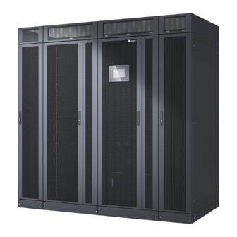
- Page 1 UPS5000-H-600 kVA-FT User Manual (PowerPOD, 100 kVA Power Module) Issue Date 2022-05-12 HUAWEI TECHNOLOGIES CO., LTD.
- Page 2 Notice The purchased products, services and features are stipulated by the contract made between Huawei and the customer. All or part of the products, services and features described in this document may not be within the purchase scope or the usage scope. Unless otherwise specified in the contract, all statements, information, and recommendations in this document are provided "AS IS"...
-
Page 3: About This Document
Indicates a hazard with a low level of risk which, if not avoided, could result in minor or moderate injury. Issue 01 (2022-05-12) Copyright © Huawei Technologies Co., Ltd. - Page 4 NOTE is used to address information not related to personal injury, equipment damage, and environment deterioration. Change History Issue Date Description 2022-05-12 This is the first official release. Issue 01 (2022-05-12) Copyright © Huawei Technologies Co., Ltd.
-
Page 5: Table Of Contents
3 Product Introduction......................26 3.1 Model Description................................26 3.2 Cabinet Description................................27 4 Component Description....................... 28 4.1 Power Module..................................28 4.2 Bypass Module..................................29 4.3 Control Module..................................31 4.3.1 Overview....................................31 Issue 01 (2022-05-12) Copyright © Huawei Technologies Co., Ltd. - Page 6 7.6.1.2 Performing a Shallow Discharge Test........................78 7.6.1.3 Performing a Capacity Test............................79 7.6.2 Lithium Battery Test................................. 81 7.6.2.1 Performing a Shallow Discharge Test........................81 7.6.2.2 Performing a Capacity Test............................82 7.6.2.3 Performing a Group Capacity Test........................... 83 Issue 01 (2022-05-12) Copyright © Huawei Technologies Co., Ltd.
- Page 7 11.6 Bypass Input Electrical Specifications........................111 11.7 Battery Electrical Specifications..........................111 11.8 Output Electrical Specifications..........................112 11.9 System Electrical Specifications..........................114 A User Interface........................115 B Alarm List..........................116 C Lifting Trolley........................117 D Acronyms and Abbreviations................... 119 Issue 01 (2022-05-12) Copyright © Huawei Technologies Co., Ltd.
-
Page 8: Safety Information
● Failure to follow the operation instructions and safety precautions on the product and in this document ● Equipment damage due to force majeure, such as earthquakes, fire, and storms Issue 01 (2022-05-12) Copyright © Huawei Technologies Co., Ltd. - Page 9 ● Keep irrelevant people away from the equipment. Only operators are allowed to access the equipment. ● Use insulated tools or tools with insulated handles, as shown in the following figure. Issue 01 (2022-05-12) Copyright © Huawei Technologies Co., Ltd.
- Page 10 Do not change the structure or installation sequence of equipment without permission. ● Do not touch a running fan with your fingers, components, screws, tools, or boards before the fan is powered off or stops running. Issue 01 (2022-05-12) Copyright © Huawei Technologies Co., Ltd.
-
Page 11: Personnel Requirements
Do not operate the equipment in the absence of a properly installed ground conductor. ● Ensure that the equipment is connected permanently to the protective ground. Before operating the equipment, check its electrical connection to ensure that it is securely grounded. Issue 01 (2022-05-12) Copyright © Huawei Technologies Co., Ltd. - Page 12 0°C. Handle cables with caution, especially at a low temperature. – Cables stored at subzero temperatures must be stored at room temperature for at least 24 hours before they are laid out. Issue 01 (2022-05-12) Copyright © Huawei Technologies Co., Ltd.
-
Page 13: Installation Environment Requirements
Install the equipment in an area far away from liquids. Do not install it under areas prone to condensation, such as under water pipes and air exhaust vents, or areas prone to water leakage, such as air conditioner vents, ventilation Issue 01 (2022-05-12) Copyright © Huawei Technologies Co., Ltd. - Page 14 Any violations must be promptly pointed out by the site manager or safety supervisor and the involved personnel should be prompted for correction. Personnel who fail to stop violations will be forbidden from working. Issue 01 (2022-05-12) Copyright © Huawei Technologies Co., Ltd.
-
Page 15: Mechanical Safety
Ensure that the wider end of the ladder is at the bottom, or protective measures have been taken at the bottom to prevent the ladder from sliding. Issue 01 (2022-05-12) Copyright © Huawei Technologies Co., Ltd. - Page 16 D ANGER When removing a heavy or unstable component from a cabinet, be aware of unstable or heavy objects on the cabinet. ● Be cautious to avoid injury when moving heavy objects. Issue 01 (2022-05-12) Copyright © Huawei Technologies Co., Ltd.
-
Page 17: Device Running Safety
Issue 01 (2022-05-12) Copyright © Huawei Technologies Co., Ltd. - Page 18 A UPS can be used to serve resistive-capacitive loads, resistive loads, and micro- inductive loads. It is recommended that a UPS not be used for pure capacitive loads, pure inductive loads, and half-wave rectification loads. A UPS does not apply to regeneration loads. Issue 01 (2022-05-12) Copyright © Huawei Technologies Co., Ltd.
-
Page 19: Battery Safety
Wear goggles, rubber gloves, and protective clothing to avoid damage caused by electrolyte in the case of electrolyte overflow. If a battery overflows, protect the skin or eyes from the leaking liquid. If the skin or eyes come in Issue 01 (2022-05-12) Copyright © Huawei Technologies Co., Ltd. - Page 20 Battery short circuits can generate high instantaneous current and release a great amount of energy, which may cause equipment damage or personal injury. To avoid battery short circuit, do not maintain batteries with power on. Issue 01 (2022-05-12) Copyright © Huawei Technologies Co., Ltd.
- Page 21 A battery can be replaced only with a battery of the same or similar model recommended by the manufacturer. ● When handling a lithium battery, do not place it upside down, tilt it, or bump it with other objects. Issue 01 (2022-05-12) Copyright © Huawei Technologies Co., Ltd.
-
Page 22: Others
UPS output voltage level or frequency. Doing so may affect the power supply to equipment. ● Exercise caution when setting battery parameters. Incorrect settings will affect the power supply and battery lifespan. Issue 01 (2022-05-12) Copyright © Huawei Technologies Co., Ltd. -
Page 23: Product Overview
● The power supply and distribution status is monitored in real time. Core parameters of the UPS power supply and distribution system are automatically inspected, so manual inspection is not required. Issue 01 (2022-05-12) Copyright © Huawei Technologies Co., Ltd. -
Page 24: Application Scenarios
Application Scenario Description Single UPS Supplies power to common loads. Parallel system Supplies power to large-sized data centers or important loads. It features high reliability and strong transient overload resistance capability. Issue 01 (2022-05-12) Copyright © Huawei Technologies Co., Ltd. - Page 25 Energy control modules (ECMs) on different UPSs are connected over parallel cables to synchronize UPS outputs to supply power to loads. If one UPS fails, another UPS continues supplying power to loads, which ensures system reliability. Issue 01 (2022-05-12) Copyright © Huawei Technologies Co., Ltd.
- Page 26 (BSC) provided in standard configuration. The UPS systems work in inverter mode or bypass mode. Figure 2-3 Typical application scenario of a dual-bus system consisting of single UPS systems Issue 01 (2022-05-12) Copyright © Huawei Technologies Co., Ltd.
-
Page 27: Working Principle
DC power into AC output. At the same time, the rectifier charges batteries over a charger. The two conversions ensure high-precision and high- quality output voltages, protecting loads from interferences such as input harmonics, glitches, and voltage transients. Issue 01 (2022-05-12) Copyright © Huawei Technologies Co., Ltd. -
Page 28: Bypass Mode
If the mains input is abnormal or the rectifier becomes abnormal, the UPS transfers to battery mode. The power module obtains energy from batteries, and the energy is converted into AC output by the inverter. Issue 01 (2022-05-12) Copyright © Huawei Technologies Co., Ltd. -
Page 29: S-Eco Mode
10%), the UPS works in inverter mode preferentially. ● In either bypass mode or inverter mode, the rectifier is started all the time and charges batteries using a charger. Issue 01 (2022-05-12) Copyright © Huawei Technologies Co., Ltd. -
Page 30: Eco Mode (The System Can Work In Eco Mode If The Model Or Hardware Does Not Support S-Eco)
In either bypass mode or inverter mode, the rectifier is started all the time and charges batteries using a charger. The ECO mode delivers a high efficiency. Figure 2-9 UPS conceptual diagram in ECO mode Issue 01 (2022-05-12) Copyright © Huawei Technologies Co., Ltd. -
Page 31: Source-Share Mode
2.5.7 Maintenance Bypass Mode When the UPS works in maintenance bypass mode, the current flows through the maintenance bypass instead of the power module. You can maintain the circuit inside the cabinet. Issue 01 (2022-05-12) Copyright © Huawei Technologies Co., Ltd. - Page 32 UPS5000-H-600 kVA-FT User Manual (PowerPOD, 100 kVA Power Module) 2 Product Overview Figure 2-11 UPS conceptual diagram in maintenance bypass mode Issue 01 (2022-05-12) Copyright © Huawei Technologies Co., Ltd.
-
Page 33: Product Introduction
The UPS5000-H-600K-FT uses 100 kVA power modules. It can expand to a maximum of 600 kVA and is compatible downwards to 200 kVA. This document uses the 600 kVA model as an example. Issue 01 (2022-05-12) Copyright © Huawei Technologies Co., Ltd. -
Page 34: Cabinet Description
(9) Intelligent detection card (10) Bypass module (11) Power modules NO TE Switches share one switch handle. Take out the handle when you operate different switches and reinstall it after the operations are complete. Issue 01 (2022-05-12) Copyright © Huawei Technologies Co., Ltd. -
Page 35: Component Description
(blinking at 0.5 Hz, on for 1s and off for 1s). ● The inverter is not started (blinking at 0.2 Hz, on for 2.5s and off for 2.5s). Issue 01 (2022-05-12) Copyright © Huawei Technologies Co., Ltd. -
Page 36: Bypass Module
The power module overload times out. ● Both active and standby energy control modules (ECMs) in the system are abnormal. ● The system runs abnormally. ● The power supply is switched is to the bypass manually. Issue 01 (2022-05-12) Copyright © Huawei Technologies Co., Ltd. - Page 37 There is no critical alarm for the bypass, or the software is being upgraded. Table 4-4 Specifications Item Specifications Dimensions (H x W x D) 200 mm x 600 mm x 600 mm Weight ≤ 50 kg Issue 01 (2022-05-12) Copyright © Huawei Technologies Co., Ltd.
-
Page 38: Control Module
The ECM controls the running of a single UPS and a parallel system, and reports the UPS status information to other monitoring modules. ● The system provides three types of CAN communication: monitoring CAN communication, intra-rack parallel CAN communication, and inter-rack parallel CAN communication. Issue 01 (2022-05-12) Copyright © Huawei Technologies Co., Ltd. - Page 39 The ECM has a minor alarm, but it does not need to be replaced. The ECM has no minor alarm or the software of the ECM is being upgraded. FAULT Steady on The ECM has a critical alarm. Issue 01 (2022-05-12) Copyright © Huawei Technologies Co., Ltd.
-
Page 40: Dry Contact Card
24 V AC and 0.6 A and the maximum values are 30 V AC and 1.0 A. During cable connection, ensure that the voltage and current do not exceed these maximum values. Issue 01 (2022-05-12) Copyright © Huawei Technologies Co., Ltd. - Page 41 Port for signal ground EPO_NO If the normally open (NO) Closing the EPO Open signal port is connected to port triggers EPO. the EPO_12V port, emergency power-off (EPO) is triggered. EPO_12V +12 V Issue 01 (2022-05-12) Copyright © Huawei Technologies Co., Ltd.
-
Page 42: Monitoring Interface Card
The MDU monitors the UPS, allows users to set parameters, delivers commands, reports system information, and displays key UPS information and parameters on the LCD. Issue 01 (2022-05-12) Copyright © Huawei Technologies Co., Ltd. - Page 43 Batt. SOC below thres., Abnormal mains, Sys maint breaker enable, Sys outp breaker enable, Maint. breaker closed, No power supplied, Mains supplies power, ECO mode, Battery test, Batt. volt. below thres, Rack output overload, Issue 01 (2022-05-12) Copyright © Huawei Technologies Co., Ltd.
- Page 44 50 m, the cross-sectional area must be 0.5–1.5 mm ● RS485 cables and FE cables must be shielded cables. Figure 4-8 Figure 4-9 are recommended wiring methods for DO ports. Figure 4-8 Wiring method 1 Issue 01 (2022-05-12) Copyright © Huawei Technologies Co., Ltd.
- Page 45 User Manual (PowerPOD, 100 kVA Power Module) 4 Component Description Figure 4-9 Wiring method 2 Figure 4-10 COM1 port pins Table 4-9 Pin definitions for the COM1 port Description RS485– RS485+ 12V_PORT Issue 01 (2022-05-12) Copyright © Huawei Technologies Co., Ltd.
- Page 46 User Manual (PowerPOD, 100 kVA Power Module) 4 Component Description Figure 4-11 COM2 port pins Table 4-10 Pin definitions for the COM2 port Description RS485+ RS485– RS485+ RS485– CANH0 CANL0 Figure 4-12 RS485 port pins Issue 01 (2022-05-12) Copyright © Huawei Technologies Co., Ltd.
-
Page 47: Intelligent Detection Card
Detects the temperatures of copper bars for batteries, bypass input, mains input, and output. ● Detects the status of the mains and bypass input switches. ● Hot-swappable and 1 U high. Figure 4-13 Intelligent detection card Issue 01 (2022-05-12) Copyright © Huawei Technologies Co., Ltd. - Page 48 ● Signal cables must be double-insulated twisted cables. If the cable length is within 25– 50 m, the cross-sectional area must be 0.5–1.5 mm ● RS485 cables and FE cables must be shielded cables. Figure 4-14 COM_OUT port pins Issue 01 (2022-05-12) Copyright © Huawei Technologies Co., Ltd.
- Page 49 Table 4-14 Pin definitions for the COM_OUT port Description RS485+ RS485– RS485+ RS485– CANH CANL Figure 4-15 FE_1 port pins Table 4-15 Pin definitions for the FE_1 port Description FE4_TX+ FE4_TX- FE4_RX+ FE4_RX- Issue 01 (2022-05-12) Copyright © Huawei Technologies Co., Ltd.
-
Page 50: Mdu
The UPS is running properly or a warning has been generated. The MDU is powered off. NO TE The indicator on the MDU panel is yellow when the bypass supplies power in non-ECO mode. Issue 01 (2022-05-12) Copyright © Huawei Technologies Co., Ltd. - Page 51 Reserved DIP switch Implements specific functions by using the DIP switch and specific buttons; controls the CAN communication build-out resistor in a parallel system. Issue 01 (2022-05-12) Copyright © Huawei Technologies Co., Ltd.
-
Page 52: Internal Switch
Rated operating 690 V AC voltage Service life (times) Mechanical life: 6000 Electrical life: 500 Dimensions (H x W x 306 mm x 106 mm x 380 mm Weight 15 kg Issue 01 (2022-05-12) Copyright © Huawei Technologies Co., Ltd. -
Page 53: Optional Components
● PDU8000-063 0DCV8- BXA001 ● PDU8000-080 0DCV8- BXA001 Battery Monitors the battery temperature. temperature sensor Parallel cable 5 m/10 m Connects UPSs in parallel. Issue 01 (2022-05-12) Copyright © Huawei Technologies Co., Ltd. -
Page 54: Installation
Rear space: Air flows out from the top of the cabinet for heat dissipation. The cabinet can be installed with the rear against a wall. If operations need to be performed at the rear, reserve at least 800 mm space for operations. Issue 01 (2022-05-12) Copyright © Huawei Technologies Co., Ltd. -
Page 55: Tools And Instruments
Prepare tools based on site requirements. Table 6-1 Tools and instruments Tools and Instruments Electric forklift Manual forklift Step ladder Rubber mallet Hammer drill (with a Hand-held electric drill Hole saw Heat gun Φ16 drill bit) Issue 01 (2022-05-12) Copyright © Huawei Technologies Co., Ltd. - Page 56 Tools and Instruments Diagonal pliers Crimping tool Wire strippers Electro-hydraulic pliers Clamp meter Multimeter Cable tie Level Insulation tape Cotton cloth Labels Electrician's knife ESD gloves Protective gloves Insulation gloves Insulated protective shoes Issue 01 (2022-05-12) Copyright © Huawei Technologies Co., Ltd.
- Page 57 User Manual (PowerPOD, 100 kVA Power Module) 6 Installation Tools and Instruments Torque screwdriver Cable cutter Brush Flat-head screwdriver (2–5 mm) Phillips screwdriver Insulated torque wrench Heat-shrink tubing Insulated adjustable wrench (M3/M4/M5/M6/M8) (M6/M8/M12/M16) Lifting trolley Issue 01 (2022-05-12) Copyright © Huawei Technologies Co., Ltd.
-
Page 58: Power Cable Selection
Mains input current 1115 Bypass input Bypass input current Output Output current (A) Battery input Nominal battery 1108 1330 (lead-acid discharge current (A) battery) Maximum battery 1062 1327 1593 discharge current (A) Issue 01 (2022-05-12) Copyright © Huawei Technologies Co., Ltd. - Page 59 Battery cables are routed over a ladder or bracket in a single layer (F in IEC60364-5-52). – Ambient temperature: 30°C – The AC voltage loss is less than 3%, and the DC voltage loss is less than Issue 01 (2022-05-12) Copyright © Huawei Technologies Co., Ltd.
-
Page 60: Unpacking
Step 2 Unpack the UPS. Step 3 After confirming that the UPS is intact, remove the bolts that secure the UPS to the pallet and remove the UPS from the pallet. Issue 01 (2022-05-12) Copyright © Huawei Technologies Co., Ltd. -
Page 61: Ups Cable Connection Reference
Step 3 Pull the marked cable out of the cabinet, cut the cable from the marked position, strip the cable, and crimp a terminal. Issue 01 (2022-05-12) Copyright © Huawei Technologies Co., Ltd. -
Page 62: Single Ups Installation
● The customer needs to purchase the expansion bolts used for securing the cabinets. Step 1 Install the cabinet. Determine the mounting holes for the cabinet using the marking-off template based on site requirements. Issue 01 (2022-05-12) Copyright © Huawei Technologies Co., Ltd. - Page 63 Drill holes and install expansion sleeves. Move the cabinet to the installation position and secure it to the floor. Install anchor baffle plates. Figure 6-5 Installing the cabinet (unit: mm) ----End Issue 01 (2022-05-12) Copyright © Huawei Technologies Co., Ltd.
- Page 64 The channel steel model, installation mode, whether holes need to be drilled on its sides, hole size, and the actual number of cabinets are determined based on site survey data. Issue 01 (2022-05-12) Copyright © Huawei Technologies Co., Ltd.
-
Page 65: Installing Copper Bars And Cables Between Cabinets
● Do not bind signal cables and power cables together. ● RS485 cables and FE cables must be shielded cables. ● The figure uses the cable connection between the UPS and the SmartLi as an example. Issue 01 (2022-05-12) Copyright © Huawei Technologies Co., Ltd. -
Page 66: Parallel System Installation
Step 2 Choose a parallel mode and connect power cables to the parallel system based on site requirements. The typical scenario of a 1+1 parallel system is used as an example. Issue 01 (2022-05-12) Copyright © Huawei Technologies Co., Ltd. -
Page 67: Connecting A Remote Epo Switch
Figure 6-10 Conceptual diagram of a 1+1 parallel system A dual-bus parallel system consisting of two parallel subsystems is used as an example. Figure 6-11 Conceptual diagram of a dual-bus parallel system ----End 6.5 Connecting a Remote EPO Switch Issue 01 (2022-05-12) Copyright © Huawei Technologies Co., Ltd. -
Page 68: Verifying The Installation
● When you use the NO status, ensure that the jumper is connected between EPO_NC and EPO_12V. When you turn on the EPO switch, EPO is triggered. 6.6 Verifying the Installation Step 1 Check that each item meets the acceptance criteria according to the following table. Issue 01 (2022-05-12) Copyright © Huawei Technologies Co., Ltd. - Page 69 0.1 ohm. AC phase sequence The mains input, bypass input, and output phase sequences are correct. Battery cables The battery strings are correctly connected to the UPS. Issue 01 (2022-05-12) Copyright © Huawei Technologies Co., Ltd.
- Page 70 Step 2 Reinstall all covers. Step 3 Close the cabinet door. The dust cover needs to be removed only prior to power- Figure 6-14 Dust cover (1) Dust cover ----End Issue 01 (2022-05-12) Copyright © Huawei Technologies Co., Ltd.
-
Page 71: System Commissioning
Insert the switch handle in place, and then rotate the switch handle. Pull out the switch handle and place it back on the tray of the front door. Ensure that the triangle arrow on the flange points to ON. Issue 01 (2022-05-12) Copyright © Huawei Technologies Co., Ltd. -
Page 72: Initial Startup
● If the UPS is powered on for the first time, you need to obtain the startup password from the Service Expert app. Skip this step if the UPS is not powered on for the first time. ● The Service Expert app can be downloaded from HUAWEI AppGallery and can only run on Android. Prerequisites The Service Expert app has been installed and registered. - Page 73 ● Set Output frequency correctly. Otherwise, loads may be affected and the UPS may not work properly. ● Set all battery parameters correctly based on site requirements. Battery parameter settings are critical to battery maintenance, battery lifespan, and UPS discharge time. Issue 01 (2022-05-12) Copyright © Huawei Technologies Co., Ltd.
- Page 74 Step 3 After you set parameters on the Settings Wizard screen, the system displays the Bypass mode and No battery alarms, which do not need to be handled. Other alarms need to be handled. Issue 01 (2022-05-12) Copyright © Huawei Technologies Co., Ltd.
-
Page 75: Starting The Inverter
Step 3 In the displayed dialog box, tap Yes to start the inverter. ----End Starting the Inverter on the WebUI Step 1 Open a browser (Internet Explorer 11 as an example) and choose Tools > Internet Options. Issue 01 (2022-05-12) Copyright © Huawei Technologies Co., Ltd. -
Page 76: Powering On Loads
A BCB box is installed. Procedure Step 1 Choose System Info > Settings > Dry Contact Set, set MUE05A connection to Enable, and set BCB connection [OL] and Battery breaker [STA] to Enable. Issue 01 (2022-05-12) Copyright © Huawei Technologies Co., Ltd. -
Page 77: Shutting Down And Powering Off The Ups
Choose Monitoring > UPS System > Running Control, and click Inv. OFF. If the inverter shuts down and the bypass is normal, the UPS transfers to bypass mode. The Bypass mode alarm is displayed on the LCD. Issue 01 (2022-05-12) Copyright © Huawei Technologies Co., Ltd. - Page 78 Insert the switch handle in place, and then rotate the switch handle. Pull out the switch handle and place it back on the tray of the front door. Ensure that the triangle arrow on the flange points to OFF. Issue 01 (2022-05-12) Copyright © Huawei Technologies Co., Ltd.
-
Page 79: Transferring To Bypass Mode Manually
The system is working in inverter mode. Context ● By default, the system works in a mode other than S-ECO. To enable the system to work in S-ECO mode, set the working mode to S-ECO mode. Issue 01 (2022-05-12) Copyright © Huawei Technologies Co., Ltd. - Page 80 After you tap OK, the system transfers to the ECO mode (5 ms interruption may occur during the transfer of the ECO mode). If the hardware supports this mode but the conditions are not met, the system works in normal mode. Issue 01 (2022-05-12) Copyright © Huawei Technologies Co., Ltd.
- Page 81 Figure 7-9 S-ECO mode parameters 1 Figure 7-10 S-ECO mode parameters 2 Figure 7-11 S-ECO mode parameters 3 Step 3 (Optional) If you set S-ECO mode in bypass mode, manually start the UPS inverter. Issue 01 (2022-05-12) Copyright © Huawei Technologies Co., Ltd.
- Page 82 If the inverter is not started, the UPS stops supplying power when the bypass is abnormal, and the system may power off. Figure 7-12 S-ECO system status (VFI) Figure 7-13 S-ECO system status (VFD) Figure 7-14 S-ECO system status (VI) ----End Issue 01 (2022-05-12) Copyright © Huawei Technologies Co., Ltd.
-
Page 83: Setting Eco Mode
LCD. Step 2 Set the ECO voltage range. Figure 7-15 ECO specifications Step 3 (Optional) If you set ECO mode in bypass mode, manually start the UPS inverter. Issue 01 (2022-05-12) Copyright © Huawei Technologies Co., Ltd. -
Page 84: Testing Batteries
● Batteries are properly connected. ● Batteries are not in equalized charging mode. Procedure Step 1 On the home screen of the LCD, choose System Info > Maintenance > Battery Maint. Issue 01 (2022-05-12) Copyright © Huawei Technologies Co., Ltd. -
Page 85: Performing A Shallow Discharge Test
UPS UI, the battery capacity displayed on the monitoring UI of the SmartLi should be used during a shallow discharge test. Otherwise, batteries may be completely discharged. Issue 01 (2022-05-12) Copyright © Huawei Technologies Co., Ltd. -
Page 86: Performing A Capacity Test
● An alarm is generated. ----End 7.6.1.3 Performing a Capacity Test Context This item allows you to fully discharge batteries. A deep discharge test is conducted to obtain the battery discharge performance data. Issue 01 (2022-05-12) Copyright © Huawei Technologies Co., Ltd. - Page 87 Save the test data obtained from the latest 36 tests. ----End Issue 01 (2022-05-12) Copyright © Huawei Technologies Co., Ltd.
-
Page 88: Lithium Battery Test
● The SmartLi generates no alarms related to lithium batteries. On the home screen of the LCD, choose System Info > Maintenance > Battery Maint. Tap Start on the right of Shallow Dis. Test to start a shallow discharge test. Issue 01 (2022-05-12) Copyright © Huawei Technologies Co., Ltd. -
Page 89: Performing A Capacity Test
Step 1 On the home screen of the LCD, choose System Info > Maintenance > Battery Maint. Step 2 Tap Start on the right of Capacity Test to start a capacity test. Issue 01 (2022-05-12) Copyright © Huawei Technologies Co., Ltd. -
Page 90: Performing A Group Capacity Test
No generator is connected to the UPS. ● The mains, batteries, charger, and discharger are normal. No overload alarm is generated. ● The SmartLi generates no alarms related to lithium batteries. Issue 01 (2022-05-12) Copyright © Huawei Technologies Co., Ltd. -
Page 91: Downloading The Test Data
Step 1 On the WebUI, choose Query > Battery Test Records, choose logs that need to be queried from the Log drop-down list box, and click Query. Figure 7-23 Battery Test Records Issue 01 (2022-05-12) Copyright © Huawei Technologies Co., Ltd. -
Page 92: Performing Epo
Choose System Info > Alarms and tap Clear Faults. After confirmation, the EPO alarm is cleared. ● On the WebUI Choose Monitoring > UPS System > Running Control > System Commands and Tests and click Clear Faults. The EPO alarm is cleared. Issue 01 (2022-05-12) Copyright © Huawei Technologies Co., Ltd. -
Page 93: Exporting Data
Figure 7-25 Exporting data WebUI ● Exporting fault information Choose Maintenance > Fault Information, set Encryption password for export, click Export Fault Information, and specify a path to save the exported data. Issue 01 (2022-05-12) Copyright © Huawei Technologies Co., Ltd. -
Page 94: Setting Hibernation Mode
This improves the system efficiency in the case of small load power and increases the power module service life. The hibernation function can be set on the WebUI. Issue 01 (2022-05-12) Copyright © Huawei Technologies Co., Ltd. - Page 95 ● WebUI: Inverter hibernation is displayed on the home page. You can choose Monitoring > Module Summary > Module N > Running Information to view the running data of the module. Issue 01 (2022-05-12) Copyright © Huawei Technologies Co., Ltd.
- Page 96 UPS5000-H-600 kVA-FT User Manual (PowerPOD, 100 kVA Power Module) 7 System Commissioning Figure 7-30 Inverter hibernation 1 Figure 7-31 Inverter hibernation 2 ----End Issue 01 (2022-05-12) Copyright © Huawei Technologies Co., Ltd.
-
Page 97: Parallel System Commissioning
Step 3 Remove the two ECMs from the upper part of the UPS cabinet control module. Loosen the captive screws on an ECM. Push the micro switch on the ejector lever. Pull the ejector lever outwards to remove the ECM from the subrack. Remove the ECM. Issue 01 (2022-05-12) Copyright © Huawei Technologies Co., Ltd. - Page 98 Step 6 Remove the jumper caps from other UPSs in the same way. Step 7 Disconnect the ground cable of the ESD wrist strap, and remove the ESD wrist strap and ESD gloves. ----End Issue 01 (2022-05-12) Copyright © Huawei Technologies Co., Ltd.
-
Page 99: Starting A Parallel System
0570-002 BPM unit abnormal. In this case, you need to power off the rack to clear the alarm. Figure 8-3 Schematic diagram Issue 01 (2022-05-12) Copyright © Huawei Technologies Co., Ltd. - Page 100 If a single UPS is not powered off after commissioning, verify on the monitoring screen that EPO has been activated successfully. Step 3 Install parallel cables between parallel cabinets. Figure 8-4 Control cable connections in a parallel system of four UPSs Issue 01 (2022-05-12) Copyright © Huawei Technologies Co., Ltd.
- Page 101 UPSs. UPSs. Battery Settings: On the LCD, choose System Info > Settings > Battery Settings. Alternatively, on the WebUI, choose Monitoring > Battery System > Running Parameter > Battery Settings. Issue 01 (2022-05-12) Copyright © Huawei Technologies Co., Ltd.
- Page 102 Step 10 Measure the output voltage of each UPS. Check that no Bypass abnormal alarm is generated for any UPS in the system. Then, all UPSs in the system supply power in bypass mode. Issue 01 (2022-05-12) Copyright © Huawei Technologies Co., Ltd.
- Page 103 Paral. Inv. ON on the LCD screen Common Functions. ----End Issue 01 (2022-05-12) Copyright © Huawei Technologies Co., Ltd.
-
Page 104: Shutting Down And Powering Off A Parallel System
● If you need to power off the entire UPS system, perform all the preceding steps. ----End 8.4 Performing EPO Procedure Step 1 Press the EPO switches connected to the dry contact cards on all UPSs one by one or press the general EPO switch. ----End Issue 01 (2022-05-12) Copyright © Huawei Technologies Co., Ltd. -
Page 105: Routine Maintenance
● Only maintenance engineers are allowed to maintain power modules and bypass modules. ● Maintain UPSs regularly based on the following requirements. Otherwise, the UPSs may fail to operate properly and the service life may be shortened. Issue 01 (2022-05-12) Copyright © Huawei Technologies Co., Ltd. -
Page 106: Monthly Maintenance
Table 9-2 Quarterly maintenance Check Item Expected Result Troubleshooting Cleanliness Wipe the cabinet surface using Remove the dust, especially a white paper and the paper from the front panel. does not turn black. Issue 01 (2022-05-12) Copyright © Huawei Technologies Co., Ltd. -
Page 107: Annual Maintenance
● Replace the cables. The allowed through- current capacity of cables is greater than the circuit breaker specifications. 9.2 Lead-Acid Battery Maintenance Issue 01 (2022-05-12) Copyright © Huawei Technologies Co., Ltd. -
Page 108: Precautions For Battery Maintenance
2. The battery terminals are intact. 3. Batteries are free from damage and cracks. 4. Batteries are free from acid leakage. 5. Batteries are not deformed or bulged. Issue 01 (2022-05-12) Copyright © Huawei Technologies Co., Ltd. -
Page 109: Quarterly Maintenance
2. Replace the battery than 3°C. temperature sensor. Battery management The settings of battery Set parameters correctly. parameter settings management parameters meet the requirements in the user manual. Issue 01 (2022-05-12) Copyright © Huawei Technologies Co., Ltd. -
Page 110: Annual Maintenance
When the UPS is backed up, 1. Locate the fault cause. discharge a battery to the 2. If the fault persists, contact undervoltage alarm threshold technical support. to refresh the capacity of the battery. Issue 01 (2022-05-12) Copyright © Huawei Technologies Co., Ltd. - Page 111 (A torque wrench is used for checking the torque. After checking that the battery screws meet the requirements, mark the screws for later check.) Issue 01 (2022-05-12) Copyright © Huawei Technologies Co., Ltd.
-
Page 112: Troubleshooting
EOD voltage and 11.3 V/cell. For details about how to rectify common faults, see Table 10-1. If any UPS5000 & SmartLi Alarm Reference or contact unmentioned faults occur, see the technical support. Issue 01 (2022-05-12) Copyright © Huawei Technologies Co., Ltd. - Page 113 The buzzer buzzes, The bypass thyristor Replace the bypass bypass is and the fault is damaged. module. abnormal indicator is on. Issue 01 (2022-05-12) Copyright © Huawei Technologies Co., Ltd.
- Page 114 Possible Cause Measure The bypass module Reduce the load, or experiences improve ventilation. overtemperature. NO TE For details about component replacement and maintenance involved in Troubleshooting and Alarm List, consult maintenance engineers. Issue 01 (2022-05-12) Copyright © Huawei Technologies Co., Ltd.
-
Page 115: Technical Specifications
Output 690 V AC/1250 A/3P 690 V AC/1250 A/3P 690 V AC/1250 A/3P Table 11-3 Internal fuse specifications AC Input Output 690 V AC/1800 A/3 PCS 690 V AC/1800 A/3 PCS Issue 01 (2022-05-12) Copyright © Huawei Technologies Co., Ltd. -
Page 116: Environmental Specifications
CQC 3108-2011 GB 7260.1-2008 YD/T 2165-2017 IEC 62040-2 Table 11-6 EMC EMC Test Item Standard Conducted emission EN/IEC 62040-2 Radiated emission EN/IEC 62040-2 Low-frequency signal interference IEC 61000-2-2 ESD immunity IEC 61000-4-2 Issue 01 (2022-05-12) Copyright © Huawei Technologies Co., Ltd. -
Page 117: Mains Input Electrical Specifications
191 V, and derated from 45% load to 35% load at 191–138 V Rated 50 Hz/60 Hz frequency Frequency 40–70 Hz range Power factor ● > 0.99 (100% load) ● > 0.98 (50% load) ● > 0.94 (30% load) Issue 01 (2022-05-12) Copyright © Huawei Technologies Co., Ltd. -
Page 118: Bypass Input Electrical Specifications
The UPS supports the SmartLi. For details about the parameters, see the User Manual . Table 11-9 Battery electrical specifications Item Specifications Battery type ● Lead-acid battery (VRLA) ● SmartLi: SmartLi 2.0 and SmartLi 3.0 are supported. Issue 01 (2022-05-12) Copyright © Huawei Technologies Co., Ltd. -
Page 119: Output Electrical Specifications
Three-phase four-wire + PE system Frequency ● In normal mode, the frequency is synchronous with the bypass input frequency. ● In battery mode, the frequency is 50 Hz/60 Hz with a tolerance of ±0.05%. Issue 01 (2022-05-12) Copyright © Huawei Technologies Co., Ltd. - Page 120 If the load of the bypass single-phase or three-phase is greater than 200%, the bypass will be shut down in 1 min, and the hardware depends on overtemperature protection. Issue 01 (2022-05-12) Copyright © Huawei Technologies Co., Ltd.
-
Page 121: System Electrical Specifications
11.9 System Electrical Specifications Table 11-11 System electrical specifications Item Specifications Parallel system reliability Redundant parallel signals ECO in a parallel system Supported Number of parallel UPSs Power distribution system TN-S, TN-C-S Issue 01 (2022-05-12) Copyright © Huawei Technologies Co., Ltd. -
Page 122: A User Interface
UPS5000-H-600 kVA-FT User Manual (PowerPOD, 100 kVA Power Module) A User Interface User Interface NO TE For details, see the UPS5000-H Monitoring Module User Manual . Issue 01 (2022-05-12) Copyright © Huawei Technologies Co., Ltd. -
Page 123: B Alarm List
UPS5000-H-600 kVA-FT User Manual (PowerPOD, 100 kVA Power Module) B Alarm List Alarm List NO TE For details about alarms, see the UPS5000 & SmartLi Alarm Reference . Issue 01 (2022-05-12) Copyright © Huawei Technologies Co., Ltd. -
Page 124: C Lifting Trolley
You can decide whether to choose it based on site requirements. Appearance Figure C-1 Lifting trolley (1) Tabletop (2) Handle (3) Lowering switch (4) Elevating pedal (5) Foot brake Issue 01 (2022-05-12) Copyright © Huawei Technologies Co., Ltd. - Page 125 Step 3 Repeatedly step on the elevating pedal to raise the tabletop to a proper height. Step 4 Lift the lowering switch to slowly lower the tabletop to the required height. ----End Issue 01 (2022-05-12) Copyright © Huawei Technologies Co., Ltd.
-
Page 126: D Acronyms And Abbreviations
Acronyms and Abbreviations American wire gauge bus synchronization controller BCB-BOX battery circuit breaker BBB-BOX battery bus bar box Conformite Europeenne economic control operation emergency power off energy control module end of discharge Issue 01 (2022-05-12) Copyright © Huawei Technologies Co., Ltd. - Page 127 SNMP Simple Network Management Protocol S-ECO super economy control operation THDi total distortion of the input current waveform THDv total harmonic distortion of output voltage Issue 01 (2022-05-12) Copyright © Huawei Technologies Co., Ltd.
- Page 128 UPS5000-H-600 kVA-FT User Manual (PowerPOD, 100 kVA Power Module) D Acronyms and Abbreviations uninterruptible power system Universal Serial Bus VRLA valve-regulated lead acid battery voltage frequency independent voltage frequency dependent voltage independent Issue 01 (2022-05-12) Copyright © Huawei Technologies Co., Ltd.
Need help?
Do you have a question about the UPS5000-H-600 kVA-FT and is the answer not in the manual?
Questions and answers