
Related Manuals for Huawei UPS5000-H-1200 Series


Summary of Contents for Huawei UPS5000-H-1200 Series
- Page 1 UPS5000-H-1200 kVA User Manual (100 kVA Power Modules) Issue Date 2020-07-15 HUAWEI TECHNOLOGIES CO., LTD.
- Page 2 Notice The purchased products, services and features are stipulated by the contract made between Huawei and the customer. All or part of the products, services and features described in this document may not be within the purchase scope or the usage scope. Unless otherwise specified in the contract, all statements, information, and recommendations in this document are provided "AS IS"...
-
Page 3: About This Document
Indicates a potentially hazardous situation which, if not avoided, could result in equipment damage, data loss, performance deterioration, or unanticipated results. NOTICE is used to address practices not related to personal injury. Issue 01 (2020-07-15) Copyright © Huawei Technologies Co., Ltd. - Page 4 Change History Changes between document issues are cumulative. The latest document issue contains all updates made in previous issues. Issue 01 (2020-07-15) This issue is the first release. Issue 01 (2020-07-15) Copyright © Huawei Technologies Co., Ltd.
-
Page 5: Table Of Contents
2.4.2.4 ECO Mode ..............................23 2.4.2.5 Joint Power Mode ............................24 2.5 System Components .............................26 2.5.1 Appearance ................................26 2.5.2 Structure ................................27 2.5.3 Power Module ..............................28 2.5.4 Bypass Module ..............................30 2.5.5 Control Module ..............................31 2.5.5.1 Overview ................................31 Issue 01 (2020-07-15) Copyright © Huawei Technologies Co., Ltd. - Page 6 4 User Interface .......................... 83 4.1 LCD Interface ..............................83 4.1.1 Main Menu ................................83 4.1.2 System Info ...............................84 4.1.2.1 Module Data ..............................85 4.1.2.2 Runn. Info..............................85 4.1.2.3 Alarms ................................89 4.1.2.4 Settings................................90 4.1.2.5 Maintenance ..............................113 Issue 01 (2020-07-15) Copyright © Huawei Technologies Co., Ltd.
- Page 7 5.8 Clearing the EPO State ............................150 5.9 Exporting Data ..............................150 5.10 Setting Hibernation Mode ..........................151 6 Routine Maintenance ......................153 6.1 UPS Maintenance ............................... 153 6.1.1 Monthly Maintenance ............................153 6.1.2 Quarterly Maintenance............................. 154 Issue 01 (2020-07-15) Copyright © Huawei Technologies Co., Ltd.
- Page 8 6.2.4 Annual Maintenance ............................157 7 Troubleshooting ........................158 8 Technical Specifications ...................... 160 A (Optional) TN-C System Application ................165 B Alarm List ..........................166 C Acronyms and Abbreviations .................... 177 Issue 01 (2020-07-15) Copyright © Huawei Technologies Co., Ltd.
-
Page 9: Safety Information
The "NOTICE", "CAUTION", "WARNING", and "DANGER" statements in this document do not cover all the safety instructions. They are only supplements to the safety instructions. Huawei will not be liable for any consequence caused by the violation of general safety requirements or design, production, and usage safety standards. - Page 10 Keep irrelevant people away from the equipment. Only operators are allowed to access the equipment. Use insulated tools or tools with insulated handles, as shown in the following figure. Issue 01 (2020-07-15) Copyright © Huawei Technologies Co., Ltd.
- Page 11 To avoid electric shock, do not connect safety extra-low voltage (SELV) circuits to telecommunication network voltage (TNV) circuits. Issue 01 (2020-07-15) Copyright © Huawei Technologies Co., Ltd.
-
Page 12: Personnel Requirements
Do not power on the equipment before it is installed or confirmed by professionals. 1.2 Personnel Requirements Personnel who plan to install or maintain Huawei equipment must receive thorough training, understand all necessary safety precautions, and be able to correctly perform all operations. - Page 13 When selecting, connecting, and routing cables, follow local safety regulations and rules. The static electricity generated by human bodies may damage the electrostatic-sensitive components on boards, for example, the large-scale integrated (LSI) circuits. Issue 01 (2020-07-15) Copyright © Huawei Technologies Co., Ltd.
-
Page 14: Installation Environment Requirements
Ensure that the equipment room provides good heat insulation, and the walls and floor are dampproof. Install a rat guard at the door of the equipment room. Issue 01 (2020-07-15) Copyright © Huawei Technologies Co., Ltd. -
Page 15: Mechanical Safety
Before hoisting objects, ensure that hoisting tools are firmly secured onto a load-bearing object or wall. Ensure that the angle formed by two hoisting cables is no more than 90 degrees, as shown in the following figure. Issue 01 (2020-07-15) Copyright © Huawei Technologies Co., Ltd. - Page 16 Do not climb higher than the fourth rung of the ladder from the top. Ensure that your body's center of gravity does not shift outside the legs of the ladder. Issue 01 (2020-07-15) Copyright © Huawei Technologies Co., Ltd.
-
Page 17: Device Running Safety
Metal shavings from drilling may short-circuit boards inside the equipment. Obtain the consent from the customer, subcontractor, and Huawei before drilling. Wear goggles and protective gloves when drilling holes. ... - Page 18 Any operation on any electrical device in an environment that has inflammable air can cause extreme danger. Strictly obey the operating environmental requirements specified in related user manuals when using or storing the device. Issue 01 (2020-07-15) Copyright © Huawei Technologies Co., Ltd.
-
Page 19: Battery Safety
Move batteries in the required direction. Do not place a battery upside down or tilt it. Keep the battery loop disconnected during installation and maintenance. Use batteries of specified models. Using batteries of other models may damage the batteries. Issue 01 (2020-07-15) Copyright © Huawei Technologies Co., Ltd. - Page 20 The site must be equipped with qualified fire extinguishing facilities, such as firefighting sands and powder fire extinguishers. To ensure battery safety and battery management accuracy, use batteries provided with the UPS by Huawei. Huawei is not responsible for any battery faults caused by batteries not provided by Huawei. Battery Installation Before installing batteries, observe the following safety precautions: ...
- Page 21 Use batteries within the allowed temperature range; otherwise, the battery performance and safety will be compromised. Do not throw a lithium battery in fire. When maintenance is complete, return the waste lithium battery to the maintenance office. Issue 01 (2020-07-15) Copyright © Huawei Technologies Co., Ltd.
-
Page 22: Others
UPS output voltage level or frequency. Doing so may affect the power supply to equipment. Exercise caution when setting battery parameters. Incorrect settings will affect the power supply and battery lifespan. Issue 01 (2020-07-15) Copyright © Huawei Technologies Co., Ltd. -
Page 23: Overview
2.2 Product Positioning and Features 2.2.1 Positioning The UPS5000-H is a high-end modular UPS launched by Huawei. It adopts online double conversion and modular redundancy design for components. Based on the digital signal processing (DSP) technology, the UPS5000-H features high efficiency and power density. -
Page 24: Highlights
50% compared with traditional solutions of combining cabinets. Easy Management and Monitoring The UPS is configured with an SNMP card, which reduces the management cost and features simple and flexible configurations. Huawei NetEco 6000 easily implements remote centralized management. 2.2.3 Features High Reliability ... -
Page 25: Application Scenarios
The UPS5000-H is suitable for power systems in various indoor scenarios, including large-sized data centers or communications centers, equipment rooms of large-sized enterprises, equipment rooms of financial systems, industrial automated equipment, and scheduling centers. Issue 01 (2020-07-15) Copyright © Huawei Technologies Co., Ltd. - Page 26 UPS5000-H-1200 kVA User Manual (100 kVA Power Modules) 2 Overview Figure 2-2 Typical application scenario of a single UPS Figure 2-3 Typical application scenario of 1+1 parallel system Issue 01 (2020-07-15) Copyright © Huawei Technologies Co., Ltd.
-
Page 27: Working Principle
The UPS uses the DSP technology for intelligent control. The power module consists of a rectifier, inverter, and DC/DC converter. The UPS converts inputs into pure high-quality sine wave outputs by using the high-frequency switching technology. Issue 01 (2020-07-15) Copyright © Huawei Technologies Co., Ltd. -
Page 28: Working Modes
DC power into AC output. At the same time, the rectifier charges batteries over a charger. The two conversions ensure high-precision and high-quality output voltages, protecting loads from interferences such as input harmonics, glitches, and voltage transients. Issue 01 (2020-07-15) Copyright © Huawei Technologies Co., Ltd. -
Page 29: Bypass Mode
The bypass power supply is not protected by the UPS and therefore is prone to the mains outage, abnormal AC voltage waveform, or abnormal frequency. Issue 01 (2020-07-15) Copyright © Huawei Technologies Co., Ltd. -
Page 30: Battery Mode
If the mains input is abnormal or the rectifier becomes abnormal, the UPS transfers to battery mode. The power module obtains DC power from batteries, and the power is converted into AC output by the inverter. Issue 01 (2020-07-15) Copyright © Huawei Technologies Co., Ltd. -
Page 31: Eco Mode
ECO voltage range, the UPS transfers from bypass mode to inverter mode. In bypass mode or inverter mode, the rectifier keeps working and charges batteries using a charger. The ECO mode delivers a high efficiency. Issue 01 (2020-07-15) Copyright © Huawei Technologies Co., Ltd. -
Page 32: Joint Power Mode
If the UPS works properly and the AC input power of the rectifiers is insufficient, the UPS transfers to joint power mode. In this case, the power module obtains energy from both the mains and batteries, and the energy is converted into AC outputs over the inverter. Issue 01 (2020-07-15) Copyright © Huawei Technologies Co., Ltd. - Page 33 UPS5000-H-1200 kVA User Manual (100 kVA Power Modules) 2 Overview Figure 2-10 Conceptual diagram in joint power mode Issue 01 (2020-07-15) Copyright © Huawei Technologies Co., Ltd.
-
Page 34: System Components
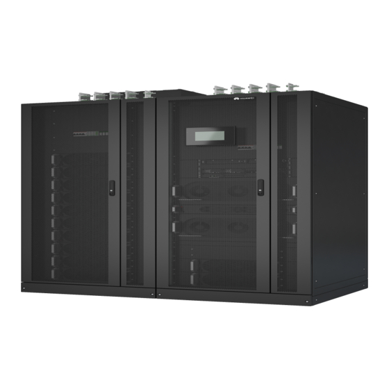
UPS5000-H-1200 kVA User Manual (100 kVA Power Modules) 2 Overview 2.5 System Components 2.5.1 Appearance Figure 2-11 Appearance Issue 01 (2020-07-15) Copyright © Huawei Technologies Co., Ltd. -
Page 35: Structure
Figure 2-12 Structure with the door open (1) Surge protective devices (2) Power (3) Surge (4) Control (SPDs) and SPD switches modules protection boxes module (5) Intelligent detection card (6) Bypass (7) Bypass control module modules Issue 01 (2020-07-15) Copyright © Huawei Technologies Co., Ltd. -
Page 36: Power Module
The module is not configured, the inverter software at short and rectifier software are being upgraded, or the intervals inverter software is being upgraded (blinking at 4 Hz, on for 0.125s and off for 0.125s). Issue 01 (2020-07-15) Copyright © Huawei Technologies Co., Ltd. - Page 37 The inverter (DC/AC) converts the inputs into sine wave outputs. Specifications Dimensions (H x W x D): 130 mm x 442 mm x 750 mm Weight: < 55 kg Rated output capacity: 100 kVA/100 kW Issue 01 (2020-07-15) Copyright © Huawei Technologies Co., Ltd.
-
Page 38: Bypass Module
(blinking at 4 Hz, on for intervals 0.125s and off for 0.125s). The bypass software is being upgraded. Alarm Yellow Steady on A minor alarm is generated for the bypass. Issue 01 (2020-07-15) Copyright © Huawei Technologies Co., Ltd. -
Page 39: Control Module
(from left to right). The four cards are hot swappable. One subrack is reserved above the dry contact card. A backfeed protection card or dry contact extended card can be inserted into this subrack. Issue 01 (2020-07-15) Copyright © Huawei Technologies Co., Ltd. -
Page 40: Ecm
Figure 2-16 ECM Table 2-4 ECM functions Silk Screen Description PARALLEL The PARALLEL port transmits parallel signals between racks. The BSC port is used in a dual-bus system to synchronize output Issue 01 (2020-07-15) Copyright © Huawei Technologies Co., Ltd. - Page 41 The ECM controls the running of a single UPS and a parallel system, and reports the UPS status information to other monitoring modules. The system provides three types of CAN communication: monitoring CAN communication, intra-rack parallel CAN communication, and inter-rack parallel CAN communication. Issue 01 (2020-07-15) Copyright © Huawei Technologies Co., Ltd.
-
Page 42: Dry Contact Card
Table 2-6 Functions of control signal ports on the dry contact card Silk Screen Signal Description Status Description Initial Status Port for monitoring battery Closed: There is a Open grounding failures battery grounding Issue 01 (2020-07-15) Copyright © Huawei Technologies Co., Ltd. - Page 43 OFF. SWITCH Port for monitoring the Open: The Open STATUS_MT maintenance switch maintenance switch is ON. SWITCH Port for signal ground Closed: The STATUS_0V maintenance switch is OFF. Issue 01 (2020-07-15) Copyright © Huawei Technologies Co., Ltd.
-
Page 44: Monitoring Interface Card
The dry contact card allows the UPS to detect and manage the switch status of the battery system (including the external battery switch) and implement remote EPO. Specifications Hot-swappable 0.5 U high 2.5.5.4 Monitoring Interface Card Issue 01 (2020-07-15) Copyright © Huawei Technologies Co., Ltd. - Page 45 Low battery SOC, Abnormal mains, DO_3 Sys maint breaker enable, Sys outp breaker enable, Maint. breaker closed, No power supplied, Mains supplies power, ECO mode, Battery test, and Batt. Volt. Below Thres. DO_4 Issue 01 (2020-07-15) Copyright © Huawei Technologies Co., Ltd.
- Page 46 0.5–1.5 mm RS485 cables and FE cables must be shielded cables. Figure 2-20 and Figure 2-21 are recommended wiring methods for DO ports. Figure 2-20 Wiring method 1 Issue 01 (2020-07-15) Copyright © Huawei Technologies Co., Ltd.
- Page 47 UPS5000-H-1200 kVA User Manual (100 kVA Power Modules) 2 Overview Figure 2-21 Wiring method 2 Figure 2-22 COM1 port pins Table 2-8 Pin definitions for the COM1 port Description RS485– RS485+ 12V_PORT Issue 01 (2020-07-15) Copyright © Huawei Technologies Co., Ltd.
- Page 48 User Manual (100 kVA Power Modules) 2 Overview Figure 2-23 COM2 port pins Table 2-9 Pin definitions for the COM2 port Description RS485+ RS485– RS485+ RS485– CANH0 CANL0 Figure 2-24 RS485 port pins Issue 01 (2020-07-15) Copyright © Huawei Technologies Co., Ltd.
-
Page 49: Intelligent Detection Card
RS485+. Twist cables to pin 2 and pin 5 into one and then connect it to RS485–. 2.5.6 Intelligent Detection Card Appearance Figure 2-25 Intelligent detection card Table 2-11 Intelligent detection card function Silk Screen Description FE_1 Reserved COM_OUT Reserved Issue 01 (2020-07-15) Copyright © Huawei Technologies Co., Ltd. - Page 50 Signal cables must be double-insulated twisted cables. If the cable length is within 25–50 m, the cross-sectional area must be 0.5–1.5 mm FE cables are shielded cables. Figure 2-26 COM_OUT port pins Table 2-13 Pin definitions for the COM_OUT port Description RS485+ RS485– RS485+ Issue 01 (2020-07-15) Copyright © Huawei Technologies Co., Ltd.
- Page 51 In the integrated UPS solution, the intelligent detection card detects the temperatures of the copper bars, switches, and environments of the battery, bypass input, mains input, output, bypass input of the switch cabinet, mains input of the switch cabinet, and output of the switch Issue 01 (2020-07-15) Copyright © Huawei Technologies Co., Ltd.
-
Page 52: Mdu
The UPS is running properly or a warning has been generated. The MDU is powered off. The indicator on the MDU panel is yellow when the bypass supplies power in non-ECO mode. Issue 01 (2020-07-15) Copyright © Huawei Technologies Co., Ltd. - Page 53 UPS over the Service Expert app. Obtain the initial startup password during deployment. View or obtain UPS running information during inspection. NOTE Only Huawei service engineers or authorized service engineers are allowed to use the WiFi module. To ensure security, remove the WiFi module immediately after use. ...
-
Page 54: Typical Configurations
ECMs on different UPSs are connected over parallel cables to synchronize UPS outputs to supply power to loads. If one UPS fails, another UPS continues supplying power to loads, which ensures system reliability. Issue 01 (2020-07-15) Copyright © Huawei Technologies Co., Ltd. -
Page 55: Dual-Bus System
You can install an optional static transfer switch (STS) to start a bus synchronization controller (BSC) provided in standard configuration. The UPS systems work in inverter mode or bypass mode. Issue 01 (2020-07-15) Copyright © Huawei Technologies Co., Ltd. -
Page 56: Optional Components
The position for installing the surge protection box subrack and ECM extended subrack is the same, and therefore the two types of subracks cannot be used simultaneously. Issue 01 (2020-07-15) Copyright © Huawei Technologies Co., Ltd. - Page 57 The fan speed can be adjusted. The ECM extended subrack does not support onsite installation. If you require this optional component, inform Huawei when you purchase the UPS so that Huawei can install the subrack before delivery. Figure 2-32 Signal cable connections for optional components Issue 01 (2020-07-15) Copyright ©...
-
Page 58: Installation
The optimal operating temperatures for valve-regulated lead-acid batteries (VRLA batteries) are 20–30° C. Operating temperatures higher than 30° C shorten the battery lifespan and operating temperatures lower than 20° C reduce the battery backup time. Issue 01 (2020-07-15) Copyright © Huawei Technologies Co., Ltd. -
Page 59: Installation Clearances
Insulate installation tools to prevent electric shocks. Prepare the following tools and meters indicated in Table 3-1 for installation. Table 3-1 Tools and meters Tools and Meters Electric pallet truck Manual pallet truck Ladder Rubber mallet Issue 01 (2020-07-15) Copyright © Huawei Technologies Co., Ltd. - Page 60 Level instrument Polyvinyl chloride Cotton cloth Label Electrician's knife (PVC) insulation tape Electrostatic Protective gloves Insulated gloves Insulation protective discharge (ESD) shoes gloves Torque screwdriver Cable cutter Brush Flat-head screwdriver (2–5 mm) Issue 01 (2020-07-15) Copyright © Huawei Technologies Co., Ltd.
-
Page 61: Preparing Power Cables And Copper Bars
Copper bars need to be prepared for the mains input, bypass input, and output, and cannot be directly connected using cables. Prepare mains input, bypass input, and output copper bars based on the following drawings and current requirements. Issue 01 (2020-07-15) Copyright © Huawei Technologies Co., Ltd. - Page 62 (1) The areas marked by the line boxes are the recommended areas for installing connector boxes. (2) The area marked by the line box is reserved for the dense busway. Figure 3-3 Front view of the distance between copper bars on the top (unit: mm) Issue 01 (2020-07-15) Copyright © Huawei Technologies Co., Ltd.
- Page 63 The rated voltage of the SmartLi is 512 V. The voltage is 408 V at the maximum discharge current. The currents listed in the table are measured at a rated voltage of 380 V. When selecting, connecting, and routing power cables, follow local safety regulations and rules. Issue 01 (2020-07-15) Copyright © Huawei Technologies Co., Ltd.
- Page 64 47 N· m input terminals Battery Crimped DT 55 mm 120 N· m input terminals Output Crimped DT 45 mm 47 N· m terminals Crimped DT 45 mm 47 N· m Issue 01 (2020-07-15) Copyright © Huawei Technologies Co., Ltd.
-
Page 65: Unpacking
If multiple loads are connected, use recommended specifications for branch circuit breakers. The circuit breaker selection principle is to protect loads and cables, and the cascading principle is to achieve specific protection. 3.1.4 Unpacking Context Issue 01 (2020-07-15) Copyright © Huawei Technologies Co., Ltd. -
Page 66: Single Ups Installation
When you install the UPS and connect cables, do not step on the front door baffle plate and the door support at the bottom of the cabinet to prevent paint flake-off and deformation. Otherwise, the front door will not be properly closed. Issue 01 (2020-07-15) Copyright © Huawei Technologies Co., Ltd. -
Page 67: Installing A Cabinet
B: mounting holes on the floor Figure 3-6 Hole dimensions (unit: mm) Step 2 Use a hammer drill to drill holes for installing expansion bolts and then install expansion sleeves in the holes. Issue 01 (2020-07-15) Copyright © Huawei Technologies Co., Ltd. - Page 68 Partially tighten the expansion bolt and vertically insert it into the hole. Knock the expansion bolt using a rubber mallet until the expansion sleeve is fully inserted into the hole. Partially tighten the expansion bolt. Remove the bolt, spring washer, and flat washer. Issue 01 (2020-07-15) Copyright © Huawei Technologies Co., Ltd.
-
Page 69: Channel Steel Installation
----End 3.2.1.2 Channel Steel Installation Prerequisites Huawei does not provide channel steel or expansion bolts used for securing channel steel. Ensure that the surface of channel steels is smooth. Figure 3-10 Recommended channel steel dimensions (unit: mm) Issue 01 (2020-07-15) -
Page 70: Ups Cable Connection Reference
Prepare terminals onsite. The length of the copper wire should be the same as that of the part of the terminal that covers the conductor. Procedure Step 1 Route a cable into the cabinet and bind it to a nearby beam. Issue 01 (2020-07-15) Copyright © Huawei Technologies Co., Ltd. -
Page 71: Installing Cables And Copper Bars
Step 4 Connect the cable with a crimped terminal to the corresponding copper bar. Step 5 Clean foreign matter inside the cabinet. ----End 3.2.3 Installing Cables and Copper Bars Context Figure 3-13 Copper bar positions (1) Battery input (2) Mains input (3) Battery PE Issue 01 (2020-07-15) Copyright © Huawei Technologies Co., Ltd. - Page 72 Step 2 (Optional) Remove the copper bars between the mains input and bypass input. Perform this step only when the mains input and bypass input use different power sources. Remove the covers. Issue 01 (2020-07-15) Copyright © Huawei Technologies Co., Ltd.
- Page 73 Remove the screws that secure the guide rail of the SPD. Place the SPD on the horizontal plate (without removing the cables). Remove the copper bars. Reinstall the SPD. Figure 3-16 Removing copper bars Step 3 Install battery cables. Issue 01 (2020-07-15) Copyright © Huawei Technologies Co., Ltd.
- Page 74 Step 4 Install top supports and covers of the battery terminal protective covers. Figure 3-18 Installing top supports and covers Step 5 Connect input and output busbars based on the top copper bar position diagram. Issue 01 (2020-07-15) Copyright © Huawei Technologies Co., Ltd.
-
Page 75: Installing Optional Components
Step 7 Install a signal cable. Figure 3-19 Installing a signal cable ----End 3.2.4 Installing Optional Components 3.2.4.1 Installing the Top Air-Flow Cabinet Install the top air-flow cabinet when the UPS is installed against a wall. Issue 01 (2020-07-15) Copyright © Huawei Technologies Co., Ltd. - Page 76 UPS5000-H-1200 kVA User Manual (100 kVA Power Modules) 3 Installation Appearance Figure 3-20 Appearance (1) Top air-flow cabinet (2) UPS Issue 01 (2020-07-15) Copyright © Huawei Technologies Co., Ltd.
- Page 77 Step 1 Determine the positions for installing cabinets on the mounting surface based on holes in the marking-off template. A: mounting holes on the channel steel B: mounting holes on the floor Figure 3-22 Fan unit hole dimensions (unit: mm) Issue 01 (2020-07-15) Copyright © Huawei Technologies Co., Ltd.
- Page 78 Remove the rear door panels from the UPS cabinets. Secure the PC panel to the inner side of the rear door panel from the outer side of the rear door using plastic rivets. Issue 01 (2020-07-15) Copyright © Huawei Technologies Co., Ltd.
- Page 79 Figure 3-24 Securing the PC panel Remove the door sills from the rear of the UPS cabinets. Figure 3-25 Removing door header sills (rear view of the cabinets) Install the accessories of the top air-flow cabinet. Issue 01 (2020-07-15) Copyright © Huawei Technologies Co., Ltd.
- Page 80 (2) UPS cabinets Step 5 Secure the cabinets. Use M12x60 expansion bolts to secure the UPS cabinets to the expansion bolt mounting holes on the floor. Figure 3-28 Securing UPS cabinets Issue 01 (2020-07-15) Copyright © Huawei Technologies Co., Ltd.
- Page 81 Remove an accessory cover from the top of the top air-flow cabinet. Connect the power cable to the 380~480V System port on the UPS and the signal cable to the XS2 port. Issue 01 (2020-07-15) Copyright © Huawei Technologies Co., Ltd.
- Page 82 If a fan is faulty, perform the following steps to replace it. Step 1 Switch off the circuit breaker, remove the cover stoppers, and remove the covers. Figure 3-31 Removing covers Step 2 Remove the cables and fan assembly. Issue 01 (2020-07-15) Copyright © Huawei Technologies Co., Ltd.
- Page 83 Figure 3-33 Removing the faulty fan Step 4 Install the new fan, and install the fan power cable and signal cable. Step 5 Reinstall the fan cover. Step 6 Reinstall the fan assembly and install cables. Issue 01 (2020-07-15) Copyright © Huawei Technologies Co., Ltd.
-
Page 84: Connecting Cables Between The Ups And The Smartli
The number and colors of cables are for reference only. Figure 3-34 Cable connection diagram (1) Connect the ground cable of the SmartLi to the battery PE of the UPS or the ground bar Issue 01 (2020-07-15) Copyright © Huawei Technologies Co., Ltd. -
Page 85: Remote Epo
----End 3.2.5 Remote EPO Huawei does not provide the EPO switch or cable. If the cable is required, the recommended cable is 22 AWG. Equip the EPO switch with a protective cover to prevent misoperations, and cover the cable with protective tubing. -
Page 86: Parallel System Installation
Step 2 Choose a parallel mode and connect cables to the parallel system based on site requirements. Figure 3-37 Conceptual diagram of a 1+1 parallel system Connect power cables according to port silk screens. Issue 01 (2020-07-15) Copyright © Huawei Technologies Co., Ltd. -
Page 87: Connecting Signal Cables
The power cables include bypass input power cables and UPS output power cables. ----End 3.3.2 Connecting Signal Cables Connecting Signal Cables to a Parallel System Figures show only the CM, which stands for the UPS. Issue 01 (2020-07-15) Copyright © Huawei Technologies Co., Ltd. - Page 88 Figure 3-39 Connecting signal cables in a 1+1 parallel system Figure 3-40 Connecting signal cables in a single UPS dual-bus system Connecting Other Signal Cables Connect signal cables for each UPS. Issue 01 (2020-07-15) Copyright © Huawei Technologies Co., Ltd.
-
Page 89: Verifying The Installation
2. There is no foreign matter on the copper bar terminals. 3. There is no foreign matter around switch terminals. 4. There is no foreign matter on the bottom plates of the cabinets. Issue 01 (2020-07-15) Copyright © Huawei Technologies Co., Ltd. - Page 90 2. After verifying the installation, reinstall all the covers. 3. Do not remove the dustproof cover before power-on to prevent dust from entering the cabinets. Issue 01 (2020-07-15) Copyright © Huawei Technologies Co., Ltd.
-
Page 91: User Interface
The LCD screen is divided into three parts: status bar, alarm bar, and information area. Figure 4-1 shows the default main menu. Table 4-1 describes the functions of the areas on the menu. Figure 4-1 Main menu Table 4-1 Main menu description Area Function Issue 01 (2020-07-15) Copyright © Huawei Technologies Co., Ltd. -
Page 92: System Info
Scrolls the page up. Returns to the upper-level menu. Logs a user out. 4.1.2 System Info On the main menu, tap System Info to access the System Info screen, as shown in Figure 4-2. Issue 01 (2020-07-15) Copyright © Huawei Technologies Co., Ltd. -
Page 93: Module Data
Select a module to view its running data. indicates the selected module, as shown in Figure 4-3. Figure 4-3 Module data 4.1.2.2 Runn. Info. On System Info, tap . The Runn. Info. screen is displayed. Issue 01 (2020-07-15) Copyright © Huawei Technologies Co., Ltd. - Page 94 AC output phase voltage Line voltage (V) AC output line voltage Phase current (A) AC output phase current Frequency (Hz) AC output frequency Power factor Proportion of output active power to output apparent power Issue 01 (2020-07-15) Copyright © Huawei Technologies Co., Ltd.
- Page 95 Bypass input line voltage Phase current (A) Bypass input phase current Frequency (Hz) Bypass input frequency Power factor Proportion of the bypass input active power to the bypass input apparent power Issue 01 (2020-07-15) Copyright © Huawei Technologies Co., Ltd.
- Page 96 If the value is greater than or equal to 1 and less than 2, the value takes 1. Table 4-9 Environment Data Item Description Ambient temperature (° C) Temperature measured by the ambient temperature and humidity sensor (An ambient temperature and humidity Issue 01 (2020-07-15) Copyright © Huawei Technologies Co., Ltd.
-
Page 97: Alarms
The alarm severity, alarm name, alarm ID, location, and generation time are displayed in the record. Historical Alarms The alarm severity, alarm name, alarm ID, location, generation time, and clearance time are displayed. Issue 01 (2020-07-15) Copyright © Huawei Technologies Co., Ltd. -
Page 98: Settings
When the UPS communicates with the northbound NMS, the function determines the position of the UPS in the NMS layout diagram. 4.1.2.4 Settings On System Info, tap . The Settings screen is displayed. Figure 4-7 Settings screen 1 Figure 4-8 Settings screen 2 Issue 01 (2020-07-15) Copyright © Huawei Technologies Co., Ltd. - Page 99 If the MDU is connected to a computer over a LAN switch or router with the DHCP function, the IP address can be allocated manually or automatically. Manual allocation is used by default. Issue 01 (2020-07-15) Copyright © Huawei Technologies Co., Ltd.
- Page 100 Specifies the subnet mask of the 255.255.255.0 0.0.0.0–255.255. Ethernet. 255.255 Gateway Specifies the Ethernet gateway. 192.168.0.1 1.0.0.0–223.255. 255.255 MAC Address Defines the physical address of network equipment and is not configurable. Issue 01 (2020-07-15) Copyright © Huawei Technologies Co., Ltd.
- Page 101 When the UPS is connected over the serial port Modbus, set this parameter based on the frame format that the upstream device Modbus supports. Northbound Set the northbound protocol type. ModbusRTU ModbusRTU, protocol type Issue 01 (2020-07-15) Copyright © Huawei Technologies Co., Ltd.
- Page 102 Figure 4-14 Ambient temperature and humidity sensor Item Description Default Value Value Range Start address 32–44 Quantity Number of cascaded ambient 0–4 temperature and humidity sensors Issue 01 (2020-07-15) Copyright © Huawei Technologies Co., Ltd.
- Page 103 Start address 16–28 Quantity Number of cascaded battery 0–4 temperature sensors Figure 4-16 BMU Item Description Default Value Value Range Start address Quantity Number of cascaded battery 0–12 monitor units (BMUs) Issue 01 (2020-07-15) Copyright © Huawei Technologies Co., Ltd.
- Page 104 Item Description Default Value Range Value Refers to a secure encrypted Enable Disable, Enable transmission protocol used to access the UPS with a terminal tool. Disable: The SSH port is disabled Issue 01 (2020-07-15) Copyright © Huawei Technologies Co., Ltd.
- Page 105 Enable: All functions are available. ModbusRTU Refers to a Modbus protocol based Enable Disable, Enable, on the RS485 bus, which is used to Read-only, connect to the NetEco. NetEco Disable: The Modbus RTU Issue 01 (2020-07-15) Copyright © Huawei Technologies Co., Ltd.
- Page 106 NetEco are enabled. Enable: All functions are available. Figure 4-19 Battery System Item Description Default Value Range Value SmartLi start SmartLi communication address address when the UPS queries SmartLi data Issue 01 (2020-07-15) Copyright © Huawei Technologies Co., Ltd.
- Page 107 User Manual (100 kVA Power Modules) 4 User Interface System Settings Figure 4-20 System Settings screen 1 Figure 4-21 System Settings screen 2 If lead-acid batteries are used, you can set Batt. temp. sensor [B_TEMP]. Issue 01 (2020-07-15) Copyright © Huawei Technologies Co., Ltd.
- Page 108 BSC master system and BSC slave system respectively in the BSC master/slave system setting. (The two UPS systems cannot be BSC master systems or BSC slave Issue 01 (2020-07-15) Copyright © Huawei Technologies Co., Ltd.
- Page 109 #1 module in rack 1 does not have a start delay. Batt. temp. The optional negative Disable Disable, Enable sensor temperature coefficient (NTC) resistor monitors the ambient Issue 01 (2020-07-15) Copyright © Huawei Technologies Co., Ltd.
- Page 110 D.G. mode Set this parameter to Enable Disable Disable, Enable when a DG connects to the input power distribution cabinet (PDC). The UPS enters the DG mode when a DG is detected Issue 01 (2020-07-15) Copyright © Huawei Technologies Co., Ltd.
- Page 111 415 V, the default upper limit is +10%.) Output volt. The output voltage can be The default 380 V: adjustment(V) slightly adjusted based on the value is 220.0, 209.0–231.0 Issue 01 (2020-07-15) Copyright © Huawei Technologies Co., Ltd.
- Page 112 If EOD restart is set to Enable, 1–1440 delay(min) the UPS starts working after the time set for EOD restart delay when the input recovers from a power failure upon battery EOD. Issue 01 (2020-07-15) Copyright © Huawei Technologies Co., Ltd.
- Page 113 ± 4.0, ± 5.0, ± 6.0 frequency bypass input frequency and the range (Hz) rated frequency is greater than the specified value, the system determines that the bypass frequency is abnormal, and the bypass is unavailable. Issue 01 (2020-07-15) Copyright © Huawei Technologies Co., Ltd.
- Page 114 Value Range Battery type Specifies the type of batteries VRLA batt. VRLA batt., connected to the UPS. lithium batt. Battery Specifies the capacity of lithium capacity(Ah) batteries connected to the UPS Issue 01 (2020-07-15) Copyright © Huawei Technologies Co., Ltd.
- Page 115 Specifies the time for a scheduled 00:00 - 06:00 00:00 - 06:00, dis. test time shallow discharge test. 06:00 - 12:00, 12:00 - 18:00, 18:00 - 24:00 Sched. shallow Specifies the interval for a 30–90 Issue 01 (2020-07-15) Copyright © Huawei Technologies Co., Ltd.
- Page 116 If lead-acid batteries are used and Number of iBOXs in System Info > Settings > iBOX Settings > Basic Param. is not 0, Batt. String Config is displayed on the iBOX Settings screen. Issue 01 (2020-07-15) Copyright © Huawei Technologies Co., Ltd.
- Page 117 Hall sensor Hall sensor Hall effect sensor used to detect 200A 200A, Hall iBOX current. sensor 600A Batt. abnormal Specifies whether BCB trips Disable Disable, Enable BCB trip when batteries are abnormal. Issue 01 (2020-07-15) Copyright © Huawei Technologies Co., Ltd.
- Page 118 DG, BCB, and PDC. Backfeed protection card (MUE06A): provides backfeed protection signals. This card can be enabled or disabled. Monitoring interface card (MUS05A): provides four configurable system output dry contact signals. Issue 01 (2020-07-15) Copyright © Huawei Technologies Co., Ltd.
- Page 119 MUS05A DO_2 Action, MUS05A DO_3 Action, MUS05A DO_4 Action MUE07A DO_1 Action, Controls the status of DO ports on the MUE07A dry MUE07A DO_2 Action, contact extended card. MUE07A DO_3 Action, Issue 01 (2020-07-15) Copyright © Huawei Technologies Co., Ltd.
- Page 120 Italian, Polish, Portuguese, Russian, Swedish, Turkish Password 000001 password If the password complexity Enable Disable, Enable complexity check is set to Disable, the user check password is required to be a Issue 01 (2020-07-15) Copyright © Huawei Technologies Co., Ltd.
-
Page 121: Maintenance
Set the date and time to the actual date and time. Time Zone Figure 4-33 Time Zone settings Set the local time zone. 4.1.2.5 Maintenance On System Info, tap . The Maintenance screen is displayed. Issue 01 (2020-07-15) Copyright © Huawei Technologies Co., Ltd. - Page 122 A proportion of battery capacity discharges during battery maintenance. This reduces the discharge time before the next charge. Do not perform battery maintenance when a generator is connected. Battery maintenance items include Forced Equalized Charging, Shallow Dis. Test, and Capacity Test. Issue 01 (2020-07-15) Copyright © Huawei Technologies Co., Ltd.
- Page 123 USB Operations You can export Fault Data, and perform Export Config., Upgrade Software, BSP Upgrade, and Import Config. on USB Operations. Issue 01 (2020-07-15) Copyright © Huawei Technologies Co., Ltd.
- Page 124 Item Description Reset Allows you to restart an iBOX or iBAT. Blink Allows you to start or stop the super fast blinking of the red indicator on the iBAT. Issue 01 (2020-07-15) Copyright © Huawei Technologies Co., Ltd.
- Page 125 Bus Capacitor Life Estimate If the service life of a capacitor is about to end, that is, Module X bus capacitor life (y) is less than 1.0, contact Huawei technical support to replace the power module. Wizard Startup The wizard startup can be used to test the bypass, mains inverter, inverter/bypass switch, battery inverter, battery charging capability, battery switch tripping, and other functions.
-
Page 126: About
[OL] to Enable. Wizard Startup can be used to test the battery switch tripping function. 4.1.2.6 About On System Info, tap About to view the model, manufacturer, monitoring version, and power version. To view the detailed version information, tap Version Info. Issue 01 (2020-07-15) Copyright © Huawei Technologies Co., Ltd. -
Page 127: System Status
User Manual (100 kVA Power Modules) 4 User Interface Figure 4-40 About screen 4.1.3 System Status On the System Status to view the mains input, bypass input, load, and battery information. Figure 4-41 System status Issue 01 (2020-07-15) Copyright © Huawei Technologies Co., Ltd. -
Page 128: Common Functions
Step 1 Open the browser and choose Tools > Internet Options. Step 2 On the Advanced tab page, ensure that Use TLS 1.0, and Use TLS 1.1 are selected and click Issue 01 (2020-07-15) Copyright © Huawei Technologies Co., Ltd. - Page 129 Other control and maintenance functions that may affect system operation are invisible and parameters cannot be set. browser Only browses the system running information. (browsing user) Issue 01 (2020-07-15) Copyright © Huawei Technologies Co., Ltd.
-
Page 130: Home
Figure 4-45 Home Item Description System View the operation status of the mains input, bypass input, battery, and Overview AC output of the system. Active Alarm View the active alarms of the system. Issue 01 (2020-07-15) Copyright © Huawei Technologies Co., Ltd. -
Page 131: Monitoring
EPO detection Specifies whether to enable EPO. EPO is Disable Disable, Enable performed only when this parameter is enabled and the EPO switch is triggered. When EPO detection is changed from Disable Issue 01 (2020-07-15) Copyright © Huawei Technologies Co., Ltd. - Page 132 Key update interval(d) 30–1095 BCB trips in case of If this parameter is set to Enable, the BCB trips Enable Disable, Enable in case of EOD. Issue 01 (2020-07-15) Copyright © Huawei Technologies Co., Ltd.
- Page 133 Specifies whether to automatically clear the Enable Disable, Enable recovery alarm and restart the power module when the rectifier or inverter shuts down due to a bus overvoltage alarm. If Bus overvoltage Issue 01 (2020-07-15) Copyright © Huawei Technologies Co., Ltd.
- Page 134 Specifies whether to start bypass mode when Enable Disable, Enable overtemp. overtemperature occurs. Battery System Battery parameter settings are critical to battery maintenance, battery lifespan, and UPS discharge time. When you set battery parameters, note the following: Issue 01 (2020-07-15) Copyright © Huawei Technologies Co., Ltd.
- Page 135 Max. batt. dis. time(h) Set the maximum battery discharge time. When 0–48 the discharge time reaches this value, the UPS Issue 01 (2020-07-15) Copyright © Huawei Technologies Co., Ltd.
- Page 136 If this parameter is set to Enable, the intelligent Disable Disable, Enable battery hibernation function is enabled. Class 1 grid hiber. time Specifies the hibernation time for class 1 power 0–30 grids. Issue 01 (2020-07-15) Copyright © Huawei Technologies Co., Ltd.
-
Page 137: Query
Performance Data, and perform Export Data. Figure 4-47 Query Item Description Historical Queries historical alarms of the system or components. Alarm Battery Test Query and export Cap. test logs and Common test logs. Issue 01 (2020-07-15) Copyright © Huawei Technologies Co., Ltd. -
Page 138: System Settings
Performance Data. 4.2.5 System Settings Figure 4-48 System settings (lead-acid battery) Figure 4-49 System settings (lithium battery) Site Configuration Table 4-16 System type Item Description Name Site name. Location Site location. Issue 01 (2020-07-15) Copyright © Huawei Technologies Co., Ltd. - Page 139 Key file of the certificate. Key password Decryption password of the key. Confirm key password Confirm the decryption password of the key. Alarm Parameters Enable or disable alarm information for components in the system. Issue 01 (2020-07-15) Copyright © Huawei Technologies Co., Ltd.
- Page 140 TLS, SSL, and No encryption are supported. SMTP port The default value is 587. Outbox Outbox address. User authentication for After Enable is selected, user authentication is required mailbox server login for server login. Issue 01 (2020-07-15) Copyright © Huawei Technologies Co., Ltd.
-
Page 141: Maintenance
Queries and exports e-labels of devices in the system. User Allows users to perform Add, Modify, Delete, Lock, and Unlock Management operations, and set passwords. Fault Exports fault information. Information BSP Upgrade Upgrades the BSP version. Issue 01 (2020-07-15) Copyright © Huawei Technologies Co., Ltd. -
Page 142: Operations
Step 1 Turn on the SPD switches 1QFS and 2QFS. Step 2 Turn on the upstream bypass and mains input switches. After the UPS is powered on, initialization begins. The MDU displays the Huawei logo and an initialization progress bar. -
Page 143: Obtaining Startup Password
Step 1 Set the language, time, network parameters, system parameters, and battery parameters on the Settings Wizard screen. Set system parameters with caution because the settings determine whether the UPS can operate normally. Issue 01 (2020-07-15) Copyright © Huawei Technologies Co., Ltd. - Page 144 Step 2 After you set parameters on the Settings Wizard screen, the system displays the Bypass mode and No battery alarms, which do not need to be handled. Other alarms need to be handled. Issue 01 (2020-07-15) Copyright © Huawei Technologies Co., Ltd.
-
Page 145: Starting The Inverter
Step 1 Open a browser (Internet Explorer 11 as an example) and choose Tools > Internet Options. Step 2 Click the Advanced tab, check that Use TLS 1.0 and Use TLS 1.1 are selected, and click Issue 01 (2020-07-15) Copyright © Huawei Technologies Co., Ltd. -
Page 146: Powering On Loads
----End 5.1.4 Powering On Loads Context After the inverter starts, the UPS transfers to inverter mode, and the Bypass mode alarm on the MDU disappears. Issue 01 (2020-07-15) Copyright © Huawei Technologies Co., Ltd. -
Page 147: Optional) Setting Parameters For The Bcb Box
5.1.6 (Optional) Setting Parameters for the Top Air-Flow Cabinet Prerequisites A top air-flow cabinet is configured. Procedure Step 1 Choose System Info > Settings > System Settings, and set Top outlet cabinet to Enable. ----End Issue 01 (2020-07-15) Copyright © Huawei Technologies Co., Ltd. -
Page 148: Shutting Down And Powering Off The Ups
Choose Monitoring > UPS System > Running Control, and click Inv. OFF. If the inverter shuts down and the bypass is normal, the UPS transfers to bypass mode. The Bypass mode alarm is displayed on the LCD. Figure 5-5 Normal bypass Issue 01 (2020-07-15) Copyright © Huawei Technologies Co., Ltd. -
Page 149: Cold-Starting The Ups Using Batteries
Step 4 Press and hold down the BATT START button on the bypass control module for more than 2 seconds. The system automatically enters the battery cold start state. The MDU displays the Huawei logo and an initialization progress bar. Step 5 After the initialization is complete, start the inverter on the LCD. -
Page 150: Transferring To Bypass Mode Manually
Hz or is steady on, press and hold down the BATT START button on the UPS bypass control module for more than 2 seconds. The system automatically enters the battery cold start state. The MDU displays the Huawei logo and an initialization progress bar. Step 6 After the MDU initialization is complete, start the inverter. - Page 151 When the bypass is abnormal, the UPS transfers to inverter mode immediately. If the inverter is not started, the UPS stops supplying power when the bypass is abnormal, and the system may power off. Figure 5-8 System status in ECO mode ----End Issue 01 (2020-07-15) Copyright © Huawei Technologies Co., Ltd.
-
Page 152: Testing Batteries
The test duration reaches the forced equalized charging protection time (12–24 h, 18 h by default). The UPS generates a battery overtemperature, overvoltage, or overcurrent alarm. An alarm is generated. ----End Issue 01 (2020-07-15) Copyright © Huawei Technologies Co., Ltd. -
Page 153: Performing A Shallow Discharge Test
The battery discharge capacity reaches the specified value (10%–50%, 20% by default). The discharge voltage reaches the warning threshold (calculated in real time). The load rate fluctuation exceeds 10%. Issue 01 (2020-07-15) Copyright © Huawei Technologies Co., Ltd. -
Page 154: Performing A Capacity Test
Based on monthly capacity test data, select the test data obtained from a capacity test that has the maximum discharge capacity as the current-month test data. Save the test data obtained from the latest 36 tests. ----End Issue 01 (2020-07-15) Copyright © Huawei Technologies Co., Ltd. -
Page 155: Lithium Battery Test
The battery discharge capacity reaches the specified value (10%–50%, 20% by default). The discharge voltage reaches the warning threshold (calculated in real time). The load rate fluctuation exceeds 10%. Issue 01 (2020-07-15) Copyright © Huawei Technologies Co., Ltd. -
Page 156: Performing A Capacity Test
The test is complete when the minimum cell voltage reaches 2.65 V. The test data is obtained from the capacity test. Save the test data obtained from the latest 36 tests. ----End Issue 01 (2020-07-15) Copyright © Huawei Technologies Co., Ltd. -
Page 157: Downloading The Test Data
EPO port of the dry contact card. Figure 5-15 EPO ports After you press the EPO button, the EPO and No power supplied alarms are displayed on the LCD. Issue 01 (2020-07-15) Copyright © Huawei Technologies Co., Ltd. -
Page 158: Clearing The Epo State
The following data can be exported: Historical alarms Active alarms Performance data Operation logs E-label Fault information This procedure describes how to export historical alarms. Issue 01 (2020-07-15) Copyright © Huawei Technologies Co., Ltd. -
Page 159: Setting Hibernation Mode
Step 1 On the WebUI, choose Monitoring > UPS System > Running Parameter, and set Paral sys hibernate to Enable. Step 2 Set Module cycle hiber period(d) to an integer ranging from 1 to 100. The default value is Issue 01 (2020-07-15) Copyright © Huawei Technologies Co., Ltd. - Page 160 UPS5000-H-1200 kVA User Manual (100 kVA Power Modules) 5 Operations Figure 5-17 System settings Click Submit after setting parameters on the WebUI. ----End Issue 01 (2020-07-15) Copyright © Huawei Technologies Co., Ltd.
-
Page 161: Routine Maintenance
Input voltage: 380 V AC, 400 If the input voltage is environment V AC, or 415 V AC (line abnormal, check the power grid voltage) status and input cable Issue 01 (2020-07-15) Copyright © Huawei Technologies Co., Ltd. -
Page 162: Quarterly Maintenance
The insulation layer of Replace the cables. (between the UPS and the cables is intact and terminals Secure the output power distribution cabinet) are free from black marks terminals. Issue 01 (2020-07-15) Copyright © Huawei Technologies Co., Ltd. -
Page 163: Lead-Acid Battery Maintenance
1. Identify the cause of an Battery temperature is 25± 5° C. abnormal battery operating operating temperature. temperature 2. The battery operating temperature is lower than 2. If the fault persists, contact Issue 01 (2020-07-15) Copyright © Huawei Technologies Co., Ltd. -
Page 164: Quarterly Maintenance
Replace the faulty cable. insulation layer does not crack. 1. Check whether the Battery voltage Equalized charging equalized charging voltage voltage: 2.35 V/cell ± 0.02 and float charging voltage V/cell Issue 01 (2020-07-15) Copyright © Huawei Technologies Co., Ltd. -
Page 165: Annual Maintenance
(A torque wrench is used for checking the torque. After checking that the battery screws meet the requirements, mark the screws for later check.) Issue 01 (2020-07-15) Copyright © Huawei Technologies Co., Ltd. -
Page 166: Troubleshooting
Close the battery switch and charge batteries until each battery has a voltage greater than the EOD voltage and 11.3 V/cell. For details about how to rectify common faults, see Table 7-1. If any unmentioned faults occur, see the alarm list chapter, or contact Huawei technical support. Table 7-1 Troubleshooting Case... - Page 167 The bypass module Reduce the load, or normal. experiences improve ventilation. overtemperature. For details about component replacement and maintenance involved in Troubleshooting and Alarm List, consult Huawei maintenance engineers. Issue 01 (2020-07-15) Copyright © Huawei Technologies Co., Ltd.
-
Page 168: Technical Specifications
When the altitude is greater than 1000 m, the power is derated as described in IEC 62040-3. The upper limit of the altitude is 4000 m. Table 8-3 Safety compliance Safety Certification Standard Issue 01 (2020-07-15) Copyright © Huawei Technologies Co., Ltd. - Page 169 0–30° C: not derated at 324–485 V AC, derated from 100% load to 45% load at 324–191 V AC, and derated from 45% load to 35% load at 191–139 V AC Issue 01 (2020-07-15) Copyright © Huawei Technologies Co., Ltd.
- Page 170 Under rated conditions, the maximum charge power of a module is 15 kW, and the charge current is limited to 30 A. Battery string sharing Supported in a parallel system (VRLA battery) Issue 01 (2020-07-15) Copyright © Huawei Technologies Co., Ltd.
- Page 171 UPS transfers to bypass mode after 200 ms or longer. Bypass overload capability: The UPS runs continuously at 135% load at 30° C; the UPS generates only alarms and uses overtemperature protection Issue 01 (2020-07-15) Copyright © Huawei Technologies Co., Ltd.
- Page 172 The UPS runs for 100 ms when the load exceeds 1000%. Table 8-9 System electrical specifications Item Specifications Parallel system reliability Redundant parallel signals ECO in a parallel system Supported Number of parallel UPSs Power distribution system TN, TN-C, TN-CS, TT Issue 01 (2020-07-15) Copyright © Huawei Technologies Co., Ltd.
-
Page 173: A (Optional) Tn-C System Application
If the TN-C system is adopted, short-circuit the input N and PE, and connect the input PE and N to terminals on the N bar. Recommended cable cross-sectional area: 240 mm Recommended screw: M16 Figure A-1 Short-circuiting the input N and PE (side view) Issue 01 (2020-07-15) Copyright © Huawei Technologies Co., Ltd. -
Page 174: B Alarm List
UPS5000-H-1200 kVA User Manual (100 kVA Power Modules) B Alarm List Alarm List This table lists only common alarms. For more information, contact Huawei technical support. Alarm ID Alarm Name Severity Possible Cause Suggestion (Alarm ID-Cause 1. Check whether cables to mains are... - Page 175 PDU is normal. If yes, the battery sampling circuit of the power module is faulty. Replace the faulty power module. 0021-1 Battery EOD Critical The battery If a BCB box is installed, check whether the Issue 01 (2020-07-15) Copyright © Huawei Technologies Co., Ltd.
- Page 176 The battery failure detector is faulty by replacing it ground with a new one. monitoring 3. If no battery grounding failure detector cable is is available, check on the dry contact faulty. Issue 01 (2020-07-15) Copyright © Huawei Technologies Co., Ltd.
- Page 177 Replace the power module if the fans ventilation are faulty. channel of the power module is obstructed. 0043-1 Fan abnormal Critical The fans of Replace the faulty power module. the power Issue 01 (2020-07-15) Copyright © Huawei Technologies Co., Ltd.
- Page 178 If all modules generate the alarm, switch off the bypass input circuit breaker. After the inverter relay is closed, switch on the bypass input circuit breaker 10s Issue 01 (2020-07-15) Copyright © Huawei Technologies Co., Ltd.
- Page 179 2. Check that the ambient temperature does ventilation not exceed 40° C. channel is 3. Check that there is no overload. blocked. The ambient temperature exceeds the Issue 01 (2020-07-15) Copyright © Huawei Technologies Co., Ltd.
- Page 180 The parallel CAN bus is disconnected. 0584-2 Inter-rack par. Minor The inter-rack Replace the inter-rack parallel cable. cable alarm parallel cable is faulty. 0584-4 The inter-rack industrial-freque synchronization cable is Issue 01 (2020-07-15) Copyright © Huawei Technologies Co., Ltd.
- Page 181 The running status is displayed. See details supplied supplied. about how to handle other alarms. 0332 Output Minor The output is The running status is displayed. See details disabled disabled. about how to handle other alarms. Issue 01 (2020-07-15) Copyright © Huawei Technologies Co., Ltd.
- Page 182 1. Check the bypass input voltage and 0096-1 ECO volt. Minor The ECO frequency. Abnormal bypass voltage or 2. Check that the rated voltage, rated Issue 01 (2020-07-15) Copyright © Huawei Technologies Co., Ltd.
- Page 183 0101-1 BSC signal Minor The dual bus abnormal connector is 2. Check the parameter settings. loose. 3. The master BSC system is not supplying power. Parameters are set incorrectly. Issue 01 (2020-07-15) Copyright © Huawei Technologies Co., Ltd.
- Page 184 5. Check that the output is grounded. Derating 6. If the alarm persists, replace the power reduces the unit or module. rated system power. The module is damaged. Issue 01 (2020-07-15) Copyright © Huawei Technologies Co., Ltd.
-
Page 185: C Acronyms And Abbreviations
BCB box BBB box battery bus bar box Conformite Europeenne digital signal processing economic control operation emergency power off energy control module end of discharge International Electrotechnical Commission Issue 01 (2020-07-15) Copyright © Huawei Technologies Co., Ltd. - Page 186 SNMP Simple Network Management Protocol total distortion of the input THDi current waveform total harmonic distortion of THDv output voltage uninterruptible power system Universal Serial Bus valve-regulated lead acid VRLA Issue 01 (2020-07-15) Copyright © Huawei Technologies Co., Ltd.
Need help?
Do you have a question about the UPS5000-H-1200 Series and is the answer not in the manual?
Questions and answers