AMX Modero NXD-700Vi Operation/Reference Manual
G4 touch panels 7” modero widescreen video touch panels with full duplex intercom
Hide thumbs
Also See for Modero NXD-700Vi:
- Operation/reference manual (274 pages) ,
- Datasheet (2 pages) ,
- Quick start manual (2 pages)

Related Manuals for AMX Modero NXD-700Vi


Summary of Contents for AMX Modero NXD-700Vi
- Page 1 Operation/Reference Guide Modero NXD-700Vi ® G4 Touch Panels 7” Modero Widescreen Video Touch Panels with Full Duplex Intercom L as t R e vi s ed: 1 /2 2 /20 0 9 To u ch P a n e l s...
- Page 2 Products repaired under this policy will carry a ninety (90) day warranty on material and labor. • AMX will notify the AMX Authorized Partner with the cost of repair, if cost is greater than the Standard Repair Fee, within five (5) days of receipt.
- Page 3 LICENSE GRANT. AMX grants to Licensee the non-exclusive right to use the AMX Software in the manner described in this License. The AMX Software is licensed, not sold. This license does not grant Licensee the right to create derivative works of the AMX Software.
-
Page 4: Fcc Information
FCC Information This device complies with Part 15 of the FCC Rules. Operation is subject to the following two conditions: (1) this device may not cause harmful interference, and (2) this device must accept any interference received; including interference that may cause undesired operation. Federal Communications Commission (FCC) Statement This equipment has been tested and found to comply with the limits for a Class B digital device, pursuant to Part 15 of... -
Page 5: Table Of Contents
Installing the NXD into drywall using Expansion Clips ... 18 Installing the NXD into a Flat Surface using #4 screws ... 21 Installing an NXD-700Vi into an (optional) Rack Mount Kit (NXA-RK7) ... 23 Wiring Guidelines for the NXD-700Vi Panels... 24 Preparing captive wires... - Page 6 If Calibration Is Not Working... 29 Configuring Communication ...31 Modero Setup and System Settings ... 31 Accessing the Setup and Protected Setup Pages... 31 Setting the Panel’s Device Number... 32 Wireless Settings Page - Wireless Access Overview ... 32 Hot Swapping... 32 Configuring a Wireless Network Access ...
- Page 7 Setup Page ... 64 Information ... 65 Project Information Page ... 66 Panel Information Page ... 67 Time & Date Setup Page ... 69 Volume Page ... 70 Supported sampling rates for WAV ... 72 Video Adjustment Page ... 72 Protected Setup Navigation Buttons ...
- Page 8 Table of Contents Checking the Panel Statistics... 114 Refreshing the Panel Statistics ... 114 Clearing the Panel Statistics ... 114 Connection Utility Page... 114 Using the Connection Utility... 116 EAP Security & Server Certificates ...117 Overview ... 117 Full Duplex Intercom ...119 Overview ...
- Page 9 EAP Authentication... 197 EAP characteristics ... 197 EAP communication overview ... 198 AMX Certificate Upload Utility ... 199 Configuring your G4 Touch Panel for USB Communication ... 199 Step 1: Setup the Panel and PC for USB Communication ... 199 Step 2: Confirm the Installation of the USB Driver on the PC ...
-
Page 11: Introduction
(either Composite or S-Video), data (via Ethernet), and audio to Modero touch panels located up to 200 feet (60.96 m) from the breakout box. NXD-700Vi panels are ideally suited for displaying full motion video and audio with overlay graphics for applications with demanding visual requirements. - Page 12 The wireless solution includes an NXA-WC80211GCF internal Wi-Fi card (FG2255-07) that allows the NXD-700Vi to communicate with a NetLinx Master via a standard 802.11g Wireless Access Point. NXD-700Vi panels feature programmable firmware that can be upgraded via either the Ethernet port, wireless interface card, or the mini-USB port.
-
Page 13: Nxd-700Vi Specifications
(4 RU - rack units high) 6.97" x 19.0" x 0.50" (17.70 cm x 48.26 cm x 1.27 cm) • NXD-700Vi (with faceplate): 5.93" x 7.87" x 3.28" (15.06 cm x 20.00 cm x 8.33 cm) • CB-TP7 Conduit/Wallbox (optional): 5.47" x 7.23" x 3.40"... - Page 14 (10 Mbps or 100 Mbps), and whether to use half duplex or full duplex mode. • NXD-700Vi panels communicate with the NetLinx Master using the ICSP protocol over Ethernet. • LEDs show communication activity and connection information: A-activity - Yellow LED lights when receiving or transmitting Ethernet data packets.
- Page 15 A/V panel over CAT5 cable (up to 200’/60.96m) and accepts either Composite or S-Video. - Although the NXD-700Vi is only sold as part of a KIT configuration, the breakout box can be purchased as a separate accessory.
-
Page 16: Nxd-700Vi Panels - Connector Layout
Mini-USB (Program) PR OG RA M FIG. 3 Connector layout on the NXD-700Vi touch panels • Upgrade Compact Flash (factory programmed with firmware): NXA-700CF256M, 256 MB COMPACT FLASH CARD (FG2116-73) NXA-700CF512M, 512 MB COMPACT FLASH CARD (FG2116-74) NXA-700CF1G, 1 G COMPACT FLASH CARD (FG2116-75) -
Page 17: Nxa-Avb/Ethernet Breakout Box
NXA-AVB/ETHERNET Breakout Box NXA-AVB/ETHERNET Breakout Box The NXA-AVB/ETHERNET Breakout Box (FIG. 4) is included as part of the NXD-700Vi Kit configuration (panel and box) but can be purchased as a separate accessory. This box facilitates the installation and distribution of video, data, and audio to Modero touch panels located up to 200 feet (60.96 m) from the AVB box. -
Page 18: Product Specifications
• Provides video/audio distribution to the video-capable touch panels over CAT5 cable up to 200 ft.(60.9 m) • This unit is included with CV5, CV7, CV10, NXD-700Vi, NXD-1000V,i and 1200V-Series Kit configurations • 2-pin 3.5 mm Phoenix connector for power to the touch panel •... -
Page 19: Wiring The Nxa-Avb/Ethernet Connectors And Cables
Indirect Connect 12 VDC power supply Power supplied via NXA-AVB box 12 VDC power supply Direct Connect FIG. 5 Sample wiring configuration on video-capable panels using this breakout box A 12 VDC-compliant power supply can also directly provide power through the unit to a target Modero panel. - Page 20 Mic Out port. This signal can be fed as a Line Level In to either an amplifier or an AMX VOL card. Either a balanced (+, -, and GND) or unbalanced (+ and GND) audio signal can be connected to this output.
-
Page 21: Wiring The Nxa-Avb/Ethernet For Unbalanced Audio
Wiring the NXA-AVB/ETHERNET for Unbalanced Audio Most domestic audio equipment has unbalanced audio inputs and outputs. This means that the audio output (left, right, or mono) appears on a single wire, and is referenced to "0 V" or "Ground". Typical connectors used are RCA "phono"... - Page 22 When connecting the MIC OUT connector to a balanced audio input (FIG. 9), use all three audio terminals (+, -, and GND), then connect the "+" terminal to the "live" signal, the "-" terminal to the "return" signal, and the "GND" terminal to the ground signal. Ground signal Return signal Balanced OUT...
-
Page 23: Nxd-700Vi Touch Panel Accessories
NXD-700Vi Touch Panel Accessories The following section outlines and describes the other AMX equipment available for these touch panels. NXA-WC80211B/CF 802.11b Wireless Card (FG2255-03) These touch panels can connect to a wireless network using an optional AMX 802.11b Wireless Interface Card shown in FIG. 1. This internal card is field-upgradeable within both models of panels. -
Page 24: Nxa-Wc80211Gcf 802.11G Wireless Card (Fg2255-07)
NXA-WC80211GCF 802.11g Wireless Card (FG2255-07) These panels can also connect to a wireless network using the (optional) 802.11g Wi-Fi CF card. This internal WIC (FIG. 2) can be purchased separately as a Wi-Fi upgrade kit from AMX. FIG. 2 NXA-WC80211GCF 802.11g wireless card This interface card (FG2255-07) is a 2.4 GHz Wi-Fi LAN CF Card which upgrades a Modero panel’s... - Page 25 If the CF metal cover plate is not present over the wireless card slot on a NXD-700Vi, NXD-1000Vi, CV7, or CV10 panel, you can use the adhesive tape to secure the terminal antenna to the surface of the new card (atop the product label).
- Page 26 - 13: (Ch 1 - 13) - Japan (802.11g) - 14: (Ch 1 - 14) - Japan (802.11b) Note: To alter the card’s default country code (North America), please contact an AMX Technical Support representative for detailed procedures and information. Operating Environment: •...
- Page 27 • EAP-TTLS • WEP 64 & 128 • WPA-PSK Touch Panel • MVP-7500 (FG5965-01) Compatibility: • MVP-8400 (FG5965-02) • NXD-700Vi (FG2258-04) • NXD-1000Vi (FGXXXXX) • NXD-CV10 (FG2259-02) • NXT-CV10 (FG2259-01/03) • NXD-CV7 (FG2258-02) • NXT-CV7 (FG2258-01) Included Accessories: • Double-sided adhesive tape •...
-
Page 29: Nxa-Cfsp Compact Flash (Fg2116-7X)
NXA-CFSP Compact Flash (FG2116-7x) Every NXD-700Vi Modero panel is shipped with a 128 MB Compact Flash card (NXA-CFSP). If possible, upgrade the panel’s internal components (Compact Flash or wireless interface cards) prior to installing or using the panel. The NXA-CFSP Compact Flash card is factory programmed with specific panel firmware and can be... -
Page 31: Installation And Upgrade Of The Internal Nxd Components
Pressing down releases the connector overlay from atop the connectors. The overlay connector must first be released before the rear back box can be removed from the NXD-CV7/NXD-700Vi panel. 4. Gently slide the connector overlay away from the back box housing. -
Page 32: Step 2: Install The New Compact Flash Memory Card
Wireless CF card (Slot #2 is located on the top slot) FIG. 4 6. Carefully lift-off the back box housing and angle it over to the side of the unit where the wires are connected to the circuit board. 7. Gently lay the back box to one side of the unit. This exposes the internal circuit board (FIG. 4). Take care not to place undue strain on the speaker cables. -
Page 33: Step 3: Close And Resecure The Nxd Panel Enclosure
6. To complete the upgrade process, either upgrade the remaining wireless card (Step 3) or close and re-secure the enclosure using the procedures in Step 3: Close and Resecure the NXD Panel Enclosure section on page 11. Card removal grooves Insert with arrow facing towards the pins FIG. -
Page 35: Installation
It is recommended that if you are planning on upgrading your flash memory, you do so before beginning any panel installations. The NXD-700Vi panel is shipped from AMX with the default Button Trim Ring already installed. The unit is also shipped with an included Trim Ring containing no button openings (a No-Button Trim Ring) that allows you, if desired, to change the default configuration of the NXD panel Faceplate to that with no-button openings. - Page 36 Trim Ring and the outer surface of the Faceplate. 10. Place the Faceplate back onto the main NXD-700Vi unit. Make sure to align the Microphone, Light, and PIR Motion sensor locations on the main unit to their respective openings on the Faceplate assembly.
- Page 37 Faceplate, and the Button Trim Ring is securely fastened. Verify the Button Trim Ring is firmly inserted onto the Faceplate and that there are no gaps between this Trim Ring and the outer surface of the Faceplate. NXD-700Vi Panel/enclosure Button latch Light Pipe latch...
- Page 38 10. Place the Faceplate back onto the main NXD-700Vi unit. Make sure to align the Microphone, Light, and PIR Motion sensor locations on the main unit to their respective openings on the Faceplate assembly. Wall Mount panels (NXDs) are contained within an outer housing (back box). This back box is not removed when installing the NXD into a Conduit Box (CB-TP7).
-
Page 39: Pre-Wall Installation Of The Conduit Box
5. Install the drywall/sheetrock before inserting the main NXD unit into the CB-TP7. The NXD-700Vi can be installed either directly into the (optional) CB-TP7 or other solid surface environment using the two different mounting options: drywall clips or solid surface screws. The following sections describe mounting the touch panel directly into a pre-wall conduit box, a solid surface or drywall, and optional NXA-RK7 Rack Mount Kit. -
Page 40: Installing The Nxd Into Drywall Using Expansion Clips
6. Carefully slide the main NXD-700Vi unit (B in FIG. 12) into the conduit box, so that all Mounting Tabs lie flush against the conduit box (C in FIG. 12). - Page 41 FIG. 13 3. Remove the Faceplate/bezel (A in FIG. 14) from the main NXD unit (B in FIG. 14) by gripping the faceplate and pulling with gentle outward force. 4. Thread the incoming power, RJ-45, Ethernet, USB, and any optional audio/video wiring (from their terminal locations) through the surface opening.
- Page 42 9. Carefully insert the main unit (with expansion clips) into the cutout until the Mounting Tabs on the NXD unit lie flush against the wall. The drywall clip set must be re-ordered from AMX if the drywall clip is bent accidentally during an installation or removed during a re-installation.
-
Page 43: Installing The Nxd Into A Flat Surface Using #4 Screws
Mounting screws (#4-40, included) are secured through two sets of circular holes located at the left and right sides of the NXD-700Vi. The most important thing to remember when mounting the NXD Wall Mount is that the outer frame (Mounting Tabs) must be installed flush against the mounting surface. - Page 44 Don’t disconnect the connectors from the touch panel. The unit must be installed with the necessary connectors before being inserted into the solid surface. 8. Carefully slide the main unit into the cutout until the Mounting Tabs of the NXD-700Vi unit lie flush against the wall.
-
Page 45: Installing An Nxd-700Vi Into An (Optional) Rack Mount Kit (Nxa-Rk7)
The NXA-RK7 is a 19" (48.3 cm) wide metal rack-mount (with black matte finish) measuring 4 rack units high. 1. Remove the Faceplate/Trim Ring assembly from the main NXD-700Vi unit. 2. Thread the incoming power, RJ-45 audio/video, Ethernet, and USB wiring (from their terminal sources) through the surface opening, leaving enough slack in the wiring to accommodate any re-positioning of the panel. -
Page 46: Wiring Guidelines For The Nxd-700Vi Panels
Wiring Guidelines for the NXD-700Vi Panels NXD-700Vi panels use a 12 VDC-compliant power supply to provide power to the panel via the 2-pin 3.5 mm mini-Phoenix PWR connector. Use the previously provided power requirement information to determine the power draw. -
Page 47: Ethernet/Rj-45 Port: Connections And Wiring
The following table shows the signal and pinout/pairing information used on the RJ-45 Audio and Video connections. Audio/Video RJ-45 Pinout Information Wire Color Function Orange/White Right Audio In Orange Right Audio In Green/White Video In Blue Mic Out White/Blue Mic Out Green Video In White/Brown... - Page 48 FIG. 19 RJ-45 wiring diagram The NXD-700Vi panel can have up to two USB-capable input devices connected for use on its different firmware and TPD4 panel pages. These input devices can consist of a keyboard or mouse. USB-connected input devices are not detected and recognized by the panel until power is cycled to the unit.
- Page 49 Modero panels are factory setup with specific demo touch panel pages. The first splash screen that appears indicates the panel is receiving power, beginning to load firmware, and preparing to display the default touch panel pages. When the panel is ready, the AMX Splash Screen is replaced by the Initial Panel Page (FIG. 20).
-
Page 50: Testing Your Calibration
FIG. 22 If the calibration was improperly set and you cannot return to the Calibration page (through the panel’s firmware); you can then access this firmware page via G4 WebControl where you can navigate to the Protected Setup page and press the Calibrate button through your VNC window. -
Page 51: If Calibration Is Not Working
If Calibration Is Not Working Cycling power to the panel should provide a baseline calibration for the particular touch panel. Re- calibrate the panel. -
Page 53: Configuring Communication
G4 panel is powered-up. The panel will not detect a USB connection of this type until after the unit cycles power. AMX Modero panels feature on-board Setup pages. Use the options in the Setup pages to access panel information and make various configuration changes. -
Page 54: Setting The Panel's Device Number
The Wireless Access Point communication parameters must match those of the pre-installed wireless CF card inside the panel. The panels allow users to connect to a wireless network through their use of the pre-installed AMX 802.11g wireless interface card to communicate with a Wireless Access Point (WAP) such as the NXA-WAP200G). -
Page 55: Configuring A Wireless Network Access
Configuring a Wireless Network Access When working with a wireless card, the first step is to configure wireless communication parameters within the Wireless Settings page. This page only configures the card to communicate to a target WAP (such as the NXA-WAP200G), it is still necessary to tell the panel which Master it should be communicating with. -
Page 56: Step 2: Configure The Card's Wireless Security Settings
This information can be found in either the Workspace - System name > Define Device section of your code (that defines the properties for your panel), or in the Device Addressing/Network Addresses section of the Tools > NetLinx Diagnostics dialog. 6. - Page 57 FIG. 27 In the Protected Setup page: 1. Press the Wireless Settings button (located on the lower-left) to open the Wireless Settings page. 2. Navigate to the Access Point MAC Address section of this page and press the on-screen Site Survey button. This action launches the Site Survey page which displays a listing of all detected WAPs in the communication range of the internal card.
- Page 58 4. Select a desired Access Point by touching the corresponding row. The up arrow and down arrow will be grayed out if there are ten or less access points detected. If there are more, then they will be enabled as appropriate so that the user can scroll through the list. 5.
-
Page 59: Configuring The Modero's Wireless Card For Unsecured Access To A Wap200G
Configuring the Modero’s wireless card for unsecured access to a WAP200G In the Protected Setup page: 1. Press the Wireless Settings button (located on the lower-left) to open the Wireless Settings page. Panel connection IP info. FIG. 28 2. Enter the SSID information by either: Automatically having it filled in by pressing the Site Survey button and from the Site Survey page, choosing an Open WAP from within the Site Survey page and then pressing the Connect button. -
Page 60: Required Information
The card should be given the SSID used by the target WAP. If this field is left blank, the unit will attempt to connect to the first available WAP. By default, all WAP200Gs use AMX as their assigned SSID value. - Page 61 After logging into the WAP200G, the default Status page appears within the web browser. These read-only values are "pulled" from some of the other user-configurable Configuration Utility pages. By default, wireless Modero panels are configured for unsecured communication to a Wireless Access Point.
- Page 62 The card should be given the SSID used by the target WAP. If this field is left blank, the unit will attempt to connect to the first available WAP. By default, all WAP200Gs use AMX as their assigned SSID value.
- Page 63 As an example, if you use TECHPUBS as your SSID, you must match this word and the case within both the Network Name (SSID) field on the touch panel’s Network Name SSID field and on the WAP’s Basic Wireless Configuration page. 5.
- Page 64 As an example, enter the word AMXPanel using a 128-bit hex digit encryption. After pressing Done, the on-screen Current Key field displays a long string of characters (separated by colons) which represents the encryption key equivalent to the word AMXPanel. This series of hex digits (26 hex digits for a 128-bit encryption key) should be entered as the Current Key into both the WAP and onto other communicating Modero panels by using the WEP Key dialog (FIG.
-
Page 65: Configuring The Modero's Wireless Card For Secured Access To A Wap200G
NetLinx Studio can be setup to run a Virtual Master where the PC acts as the Master by supplying its own IP Address for communication to the panel. For a PC to establish a USB connection with a Modero panel, it must have the AMX USBLAN driver installed. -
Page 66: Usb
The AMX USBLAN driver is included with both NetLinx Studio2 and TPDesign4, and can also be downloaded as a stand-alone application from www.amx.com. If you haven’t already done so, download and install the latest versions of NetLinx Studio2 and TPDesign4 (from www.amx.com), and restart your PC. -
Page 67: Configure A Virtual Netlinx Master Using Netlinx Studio
It also indicates that the AMX USBLAN driver does not contain a Microsoft signature. FIG. 38 8. Click Yes to proceed with the driver installation. Once the installation is complete, the panel and PC are ready to communicate via USB. - Page 68 FIG. 39 3. Click the Communications Settings button to open the Communications Settings dialog. 4. Click the NetLinx Master radio button (from the Platform Selection section). 5. Click the Virtual Master radio button (from the Transport Connection Option section). 6. Click the Edit Settings button to open the Virtual NetLinx Master Settings dialog (FIG. 39). 7.
- Page 69 1. Verify the panel has been configured to communicate with the Wireless Access Point and verify the signal strength quality bargraph is On. 2. Launch NetLinx Studio 2.x (default location is Start > Programs > AMX Control Disc > NetLinx Studio 2 > NetLinx Studio 2).
- Page 70 Enter this IP into the Master IP/URL field on the System Settings page FIG. 40 4. Click the Communications Settings button to open the Communications Settings dialog. 5. Click on the NetLinx Master radio button (from the Platform Selection section) to indicate that you are working as a NetLinx Master.
-
Page 71: Ethernet
By selecting URL, the System Number field becomes read-only (grey) because the panel pulls this value directly from the communicating target Master (virtual or not). A Virtual Master system value can be set within the active AMX software applications such as: NetLinx Studio, TPD4, or IREdit. - Page 72 Refer to the G4 Web Control Page section on page 100 for more detailed field information. Verify your NetLinx Master (ME260/64 or NI-Series) has been installed with the latest firmware KIT file from www.amx.com. Refer to your NetLinx Master instruction manual for more detailed information on the use of the new web-based NetLinx Security.
- Page 73 9. From the Web Name keyboard, enter a unique alpha-numeric string to identify this panel. This information is used by the NetLinx Security Web Server to display on-screen links to the panel. The on-screen links use the IP Address of the panel and not the name for communication (FIG. 43). FIG.
- Page 74 If the Master has been previously configured for secured communication, click OK to accept the AMX SSL certificate (if SSL is enabled) and then enter a valid username and password into the fields within the Login dialog. 4. Click OK to enter the information and proceed to the Master’s Manage WebControl Connections window.
- Page 75 6. Click on the G4 panel name link associated with the target panel. A secondary web browser window appears on the screen (FIG. 45). FIG. 45 7. Click Yes from the Security Alert popup window to agree to the installation of the G4 WebControl application on your computer.
- Page 76 10. Enter the Web Control session password into the Session Password field (FIG. 46). This password was previously entered into the Web Control Password field within the G4 Web Control page on the panel. 11. Click OK to send the password to the panel and begin the session. A confirmation message appears stating "Please wait, Initial screen loading..".
-
Page 77: Upgrading Modero Firmware
Panel Calibration section on page 27. The latest NXD-700Vi firmware kit file is now panel-specific. Only NXD-700Vi firmware should be loaded onto ithis specific panel type. This new firmware also provides both backwards compatibility with the previous 802.11b cards and new security protocols for the new 802.11g wireless CF card. - Page 78 (turning the System Connection icon green). 8. Navigate back to the System Settings page. 1. Launch NetLinx Studio 2.x (default location is Start > Programs > AMX Control Disc > NetLinx Studio 2 > NetLinx Studio 2).
-
Page 79: Step 3: Confirm And Upgrade The Firmware Via The Usb Port
7. From within this dialog enter the System number (default is 1). 8. Click OK three times to close the open dialogs, save your settings, and return to the main NetLinx Studio application. 9. Click the OnLine Tree tab in the Workspace window to view the devices on the Virtual System. The default System value is one. - Page 80 5. If the panel firmware being used is not current, download the latest Kit file by first logging in to www.amx.com and then navigate to Tech Center > Firmware Files and from within the Modero section of the web page locate your Modero panel.
- Page 81 NetLinx Master instruction manual to use an address. Note the IP Address and Gateway information. 2. Launch NetLinx Studio 2.x (default location is Start > Programs > AMX Control Disc > NetLinx Studio 2 > NetLinx Studio 2).
- Page 82 By selecting URL, the System Number field becomes read-only (grey) because the panel pulls this value directly from the communicating target Master (virtual or not). A Virtual Master system value can be set within the active AMX software applications such as: NetLinx Studio, TPD4, or IREdit.
- Page 83 4. If the panel firmware being used is not current, download the latest Kit file by first logging in to www.amx.com and then navigate to Tech Center > Firmware Files and from within the Modero section of the web page locate your Modero panel.
- Page 84 Selected Firmware file FIG. 52 7. Select the panel’s Kit file from the Files section (FIG. 52). 8. Enter the Device value associated with the panel and the System number associated with the Master (listed in the OnLine Tree tab of the Workspace window). The Port field is greyed-out. 9.
-
Page 85: Protected Setup
This section describes each firmware page and their specific functional elements. These Setup Navigation Buttons (FIG. 53) appear on the left of the panel screen when the Setup page is currently active. Closes the Setup page Press to access the Protected Setup page for panel calibration and to access security release passwords and connection settings. - Page 86 This page (FIG. 54) centers around basic Modero panel properties such as: Connection Status of the panel, Display Timeout, Inactivity Page Flip Time, Inactivity page file, and the Panel Brightness. FIG. 54 The elements of the Setup page are described in the table below: Exit: Returns you to the Main touch panel page.
- Page 87 Inactivity Page Flip Sets the number of minutes of inactivity before the panel automatically flips to a Timeout: pre-selected touch panel page. When the device goes into this inactivity mode, the LCD does not power-down. • Press the UP/DN buttons to increase/decrease the time the panel can remain inactive before it flips to the preset page.
-
Page 88: Project Information Page
Displays the purchase order information. AMX IR 38k Assigned Port: Displays the AMX 38 kHz IR channel port used by the IR receiver on the panel. • This information is pulled by the panel from AMX IR Receivers section of the TPD4 Project Properties >... -
Page 89: Panel Information Page
AMX IR 455k Displays the AMX 455 kHz IR channel port used by the IR receiver on the Assigned Port: panel. This information is pulled by the panel from AMX IR Receivers section of the TPD4 Project Properties > IR Emitters & Receivers tab. - Page 90 Displays the pixel width being used to display the incoming video signal on the Modero panel. • Maximum available screen width on a NXD-700Vi Modero panel is 800 pixels. Screen Height: Displays the pixel height being used to display the incoming video signal on the Modero panel.
-
Page 91: Time & Date Setup Page
Time & Date Setup Page The options on the Time & Date Setup page (FIG. 58) allow you to set and adjust time and date information on the NetLinx Master. If the time and/or date on the Master is modified, all connected devices will be updated to reflect the new information. -
Page 92: Volume Page
Time & Date Setup Page (Cont.) Set Date/Time: Use the UP/DN arrow buttons to adjust the Master’s calendar date and time. The blue icon indicates which field is currently selected (see FIG. 58). • Year range = 2000 - 2037 •... -
Page 93: Volume Page
Volume Page Elements (Cont.) Default Panel Sounds: Sets the Modero panel to play various sounds. • Activating the Button Hit button plays a default sound when you touch an active button. • Activating the Button Miss button plays a default sound when you touch a non-active button or any area outside of the active button •... -
Page 94: Supported Sampling Rates For Wav
Supported sampling rates for WAV The following is a listing of supported sampling rates associated for WAV files played on NXD-700Vi panels. Some WAV files currently played on Modero's may not work on these panels. The supported sampling rates for WAV files are: Supported WAV Sampling Rates •... - Page 95 The elements of the Video Setup page are described in the table below: Back: Saves the changes and returns you to the previously active touch panel page. Connection Status icon: This visual display of the connection status allows the user to have a current visual update of the panel’s connection status regardless of what page is currently active.
-
Page 96: Protected Setup Navigation Buttons
The Protected Setup Navigation Buttons (FIG. 61) appear on the left of the panel screen when the Protected Setup page is currently active. Press to access the System Settings page where you can configure communication settings for the NetLinx Master and the panel. Press to access the Wireless Settings page where you can setup the wireless connection parameters used by the internal NXA-WC80211GCF wireless interface card. -
Page 97: Protected Setup
The Protected Setup page (FIG. 62) centers around the properties used by the panel to properly communicate with the NetLinx Master. Enter the factory default password (1988) into the password keypad to access this page. FIG. 62 The elements of the Protected Setup page are described in the table below: Back: Saves the changes and returns you to the previously active touch panel page. - Page 98 • The Remove User Pages button allows you remove all current TPD4 touch panel pages currently on the panel (including the pre-installed AMX Demo pages). - Pressing this button launches a Confirmation dialog (FIG. 63) which asks you to confirm your selection.
- Page 99 Channel Code Channel Port 3,132 BUTTON 3,50 Level Port Address Port Channel Code Address Code FIG. 64 The System Settings page (FIG. 65) sets the Secondary DNS Address information with its corresponding IP communication parameters, NetLinx Master communication settings, and reads the device number assigned to the Modero panel.
-
Page 100: System Settings Page
• Choices are: Auto, 10 Half Duplex, 10 Full Duplex, 100 Half Duplex, or 100 Full Duplex. MAC Address Displays a read-only field that is factory set by AMX for the built-in Ethernet interface. Master Connection: Sets the NetLinx Master communication values:... -
Page 101: Wireless Settings Page
System Settings Page Elements (Cont.) Master Connection (Cont.): System Number Allows you to enter a system number. Default value is 0 (zero). (ETHERNET Only - disabled when USB is selected) Master IP/URL Sets the Master IP or URL of the NetLinx Master. (ETHERNET Only - disabled when USB is selected) Master Port Number Allows you to enter the port number used with the NetLinx Master. - Page 102 Wireless Settings Page (Cont.) IP Settings: Sets the IP communication values for the panel: DHCP/STATIC Sets the panel to either DHCP or Static communication modes. • DHCP - a temporary IP Addresses is assigned to the panel by a DHCP server.
- Page 103 • Refer to the Wireless Security Page section on page 82 for details. • For information on uploading a certificate file, refer to the AMX Certificate Upload Utility section on page 199.
-
Page 104: Secondary Connection Page
Wireless Settings Page (Cont.) RF Link Info (Cont.): Link Quality Displays the quality of the link from the wireless NIC to the Wireless Access Point (direct sequence spread spectrum) in real time (None, Poor, Fair, Good, Very Good, and Excellent). •... -
Page 105: Open (Clear Text) Settings
802.11g wireless card Open (Clear Text) Settings Press the Open (Clear Text) button to open the Open (Clear Text) Settings page (FIG. 67). FIG. 67... -
Page 106: Static Wep Settings
• Make sure this setting is the same for all points in your wireless network. • NXA-WAP200Gs use AMX as their default SSID. • If this field is left blank, the panel will attempt to connect to the first available WAP. - Page 107 • The Passphrase generator is case sensitive. Note: This Key generator is unique to Modero panels and does not generate the same keys as non-AMX wireless devices. For example, a Current Key string generated anywhere else will not match those created on Modero pan- els.
-
Page 108: Wpa-Psk Settings
Static WEP Settings (Cont.) Current Key: Displays the current WEP key in use. • When working with a single panel and a single WAP, it is recommended that you manually enter the Current Key from the WAP into the selected WEP Key. - Page 109 • Make sure this setting is the same for all points in your wireless network. • NXA-WAP200Gs use AMX as their default SSID. • If this field is left blank, the panel will attempt to connect to the first available WAP.
-
Page 110: Eap-Leap Settings
• Make sure this setting is the same for all points in your wireless network. • NXA-WAP200Gs use AMX as their default SSID. • With EAP security, the SSID of the WAP must be entered. If it is left blank, the panel will try to connect to the first access point detected that supports EAP. - Page 111 This works in tandem with the Password string which is similar to the password entered to gain access to a secured workstation. Typ- ically, this is in the form of a username such as: jdoe@amx.com. Password: Opens an on-screen keyboard. Enter the network password string specified...
-
Page 112: Eap-Fast Settings
FIG. 71 Refer to the EAP Authentication section on page 197 for further details on these security options. Refer to FIG. 71 for an example of what a typical EAP-LEAP system configuration page would like. EAP-FAST Settings Press the EAP-FAST button to open the EAP-FAST Settings dialog (FIG. 72). FIG. - Page 113 This works in tandem with the Password string which is similar to the password entered to gain access to a secured workstation. Typ- ically, this is in the form of a username such as: jdoe@amx.com. Anonymous Identity: Opens an on-screen keyboard.
-
Page 114: Eap-Peap Settings
EAP-FAST Settings (Cont.) PAC File Location: This field is used when the previous Automatic PAC Provisioning option has been Disabled. • When pressed, the panel displays an on-screen PAC File Location keyboard which allows you to enter the name of the file containing the PAC shared secret credentials for use in authentication. - Page 115 This works in tandem with the Password string which is similar to the password entered to gain access to a secured workstation. Typ- ically, this is in the form of a username such as: jdoe@amx.com. Password: Opens an on-screen keyboard. Enter the network password string specified...
-
Page 116: Eap-Ttls Settings
• Make sure this setting is the same for all points in your wireless network. • NXA-WAP200Gs use AMX as their default SSID. • With EAP security, the SSID of the WAP must be entered. If it is left blank, the panel will try to connect to the first access point detected that supports EAP. - Page 117 This works in tandem with the Password string which is similar to the password entered to gain access to a secured workstation. Typically, this is in the form of a username such as: jdoe@amx.com. Anonymous Identity: Opens an on-screen keyboard. Enter an IT provided alpha-numeric string which (similar to the username) used as the identity, but that does not repre- sent a real user.
-
Page 118: Eap-Tls Settings
Note: This information is similar to a username used to login to a secured server or workstation. This works in tandem with the Password string which is similar to the password entered to gain access to a secured workstation. Typ- ically, this is in the form of a username such as: jdoe@amx.com. -
Page 119: Client Certificate Configuration
EAP-TLS Settings (Cont.) Certificate Authority: When pressed, the panel displays an on-screen Certificate Authority (CA) File Location keyboard which allows you to enter the name of the certificate authority file which is used to validate the server certificate. This field is optional. If a server certificate is used, it should first be downloaded into the panel and the Certificate Authority field should then be set to the name of that certificate file. - Page 120 AMX supports the following security certificates PEM (Privacy Enhanced Mail) DER (Distinguished Encoding Rules) PKCS12 (Public Key Cryptography Standard #12) PKCS12 files are frequently generated by Microsoft certificate applications. Otherwise, PEM is more common. Certificate files frequently use 5 file extensions. It can be confusing because there is not a one to one correspondence.
-
Page 121: Calibration Page
Calibration Page This page (FIG. 76) allows you to calibrate the touch panel using a pre-selected touch driver. Press and hold the grey Front Setup Access button (below the Modero LCD) for 6 seconds to access the Calibration page. Press the crosshairs to calibrate the panel and return to the last active firmware page. FIG. -
Page 122: G4 Web Control Page
An on-board VNC (Virtual Network Computing) server allows the panel to connect to any remote PC running a VNC client. Once connected, the client can view and control the panel remotely. The options on this page allow you to enable/disable G4 Web Control functionality(FIG. 77). FIG. - Page 123 G4 Web Control Timeout: Sets the length of time (in minutes) that the panel can remain idle (no cursor movements) before the G4 Web Control session is terminated. • Minimum value = 0 minutes (panel never times out) • Maximum value = 240 minutes (panel times out after 240 minutes) FIG.
-
Page 124: Sensor Setup
The Sensor Setup page (FIG. 79) allows you to adjust the Light and Motion Sensor parameters on a Modero touch panel. FIG. 79 Sensor Setup page A light level value between the Minimum and Maximum DIM Mode values delivers an average light level. - Page 125 Light Sensor: Allows you to monitor and alter the sensitivity of the Modero panel light sensor: • The Light Sensor Level field indicates the level used to report the light sensor level back to the NetLinx Master (set in TPD4) (read-only). •...
- Page 126 Wake Panel On Motion The Wake Panel Sensitivity relates to the sensitivity of the motion sensor to Sense: detect motion and wake the panel accordingly. • Toggle the Enable/Enabled button to either active/inactive this feature: - Enable - activates this feature. Activating this feature reactivates the panel from a panel timeout (sleep) mode.
-
Page 127: Other Settings
9. Set the Minimum brightness of the Dimmer (Dim Mode Max Level) below the detected drop. This will make sure that the panel does not react to variations in the lighting conditions of a normal working environment. The minimum (lower level) of the dimmer should be at least 10% lower than the minimum detected level (ex: lower dimmer level at 30% if the detected lighting of the room is at 40%). -
Page 128: Image Caching
The Image Caching page (FIG. 81) configures the allocation of memory for image caching. The G4 graphics engine caches images to decrease load time of previously viewed images. RAM caching is always enabled, and images (both static and dynamic) are stored in the RAM cache as they are viewed. The size of RAM cache is automatically configured to take into account available memory versus memory that may be needed by the panel later. - Page 129 Image Cache Settings: Allocates Flash memory for image caching. Flash Cache Size Press the Up and Down arrows to add and remove memory. Flash memory allocation cannot exceed the amount of Flash memory on the panel. Flash/RAM Cache Expires Press the Up and Down arrows to change the amount of time the images stay in cache memory.
-
Page 130: Password Setup
In the Protected Setup page: 1. Press the Cache button in the Protected Setup Navigation Buttons section. This opens the Image Cache page. 2. Set the cache expiration in the field Flash/RAM Cache Expires. The Up and Down arrows increment through the available time frames. -
Page 131: Sip Settings
The elements of the Password Setup page are described in the table below: Back: Saves the changes and returns you to the previously active touch panel page. Connection Status icon: This visual display of the connection status allows the user to have a current visual update of the panel’s connection status regardless of what page is currently active. - Page 132 Features on this page include: Back: Saves all changes and returns to the previous page. Connection Status icon: The icon in the upper-right corner of each Setup page shows online/offline state of the panel to the master. • Bright red - disconnected •...
-
Page 133: Panel Logs
The Tools button provides a menu to select either the Panel Logs Page section on page 111, the Panel Statistics Page section on page 112, or the Connection Utility Page section on page 114. Select any of the options to access that page. FIG. -
Page 134: Panel Statistics
Features on this page include: Back: Saves all changes and returns to the previous page. Connection Status icon: The icon in the upper-right corner of each Setup page shows online/offline state of the panel to the master. • Bright red - disconnected •... - Page 135 FIG. 86 Features on this page include: Back: Saves all changes and returns to the previous page. Connection Status icon: The icon in the upper-right corner of each Setup page shows online/offline state of the panel to the master. • Bright red - disconnected •...
-
Page 136: Connection Utility
Wireless Statistics The Wireless connection statistics for the panel. Clear Clears all panel connection statistics. Refresh Refreshes all panel connection statistics. 1. Press the Tools button in the Protected Setup Navigation Buttons section. This opens the Tools menu. 2. Within the Tools menu, press the Panel Statistics button. All connection statistics are contained on this page, e.g., Received, Processed, and Dropped ICSP Messages. - Page 137 Features on this page include: Close: Closes the Connection Utility popup. Connection Status icon: The icon in the upper-right corner of the utility provides a constant visual i indication of current connection status. A message is sent to the master once per second and expects a response. •...
- Page 138 1. Press the Tools button in the Protected Setup Navigation Buttons section. This opens the Tools menu. 2. Within the Tools menu, press the Connection Utility button. This launches the Connection Utility pop-up window. 3. Move the panel throughout your wireless network, and changes within the utility. The Connection Information notes the IP of the connected master and the IP of your panel.
-
Page 139: Eap Security & Server Certificates
EAP Security & Server Certificates Overview The following EAP types all support a server certificate: EAP-PEAP EAP-TTLS EAP-TLS All three of these certificate-using security methods are documented in the following sections. EAP Authentication goes a step beyond just encrypting data transfers, but also requires that a set of credentials be validated before the client (panel) is allowed to connect to the rest of the network (FIG. -
Page 141: Setup
By utilizing VoIP intercom, system integration is simple and calls sound incredibly clear. Download the module for the intercom panel from www.amx.com, and include it in your NetLinx project file. For searching purposes, the module manufacturer is AMX and the model is Intercom. - Page 142 1. Select the Setup button on your intercom page. 2. Press the up or down arrows to increment the timeout up by 1 second in each direction. If your call exceeds your session timeout the panel provides you with a popup (FIG. 90) to extend the session. Extend Call Popup FIG.
-
Page 143: Advanced Setup
The intercom’s advanced setup pages are accessed through the intercom setup pages. The advanced pages allow you to set the panel intercom to be monitored, to monitor other intercom panels, and to name the panel. It is important to name the intercom panel; the name is displayed in other panels’ intercom call directory pages. - Page 144 5. Press Back to return to the intercom setup pages. 6. Press Exit when you are finished. 1. Select the Setup button on your intercom page. 2. On the intercom setup page, press Advanced Setup. This launches the password numeric keypad. 3.
-
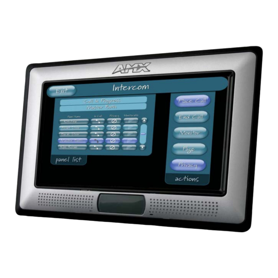
Page 145: Creating Intercom
The module for duplex intercom capable panels includes user pages. While you can create your own intercom directory page (see Creating Intercom Pages section on page 126), it is possible to use the panel with the page below. Sample Intercom Page FIG. - Page 146 No. Name Description Panel Directory Room Name The name of a panel in the intercom directory. You can call the panel, enact privacy against the panel and monitor the panel. Panel Directory Room Name The name of a panel in the intercom directory.
- Page 147 No. Name Description Monitor Panel Display only; indicates the panel is being monitored by another panel. Monitor Panel Display only; indicates the panel is being monitored by another panel. Monitor Panel Display only; indicates the panel is being monitored by another panel.
- Page 148 The easiest method of creating your own intercom pages is to start with the pages provided by AMX in the module download .ZIP file. You can change the aesthetics of the pages as long as the channel, address, level and links remain untouched.
-
Page 149: Button Assignments
Programming Overview You can program the touch panel, using the commands in this section, to perform a wide variety of operations using Send_Commands and variable text commands. A device must first be defined in the NetLinx programming language with values for the Device: Port: System (in all programming examples - Panel is used in place of these values and represents all Modero panels). - Page 150 Syntax: @CPG Clear all popup "'@CPG-<popup group name>'" pages from Variable: specified popup popup group name = 1 - 50 ASCII characters. Name of the popup group. group. Example: SEND_COMMAND Panel,"'@CPG-Group1'" Clears all popup pages from the popup group ’Group1’. @DPG Syntax: Delete a specific...
- Page 151 Syntax: @PHT Set the hide effect "'@PHT-<popup page name>;<hide effect time>'" time for the Variable: specified popup popup page name = 1 - 50 ASCII characters. Name of the page the popup is displayed page. hide effect time = Given in 1/10ths of a second. Example: SEND_COMMAND Panel,"'@PHT-Popup1;50'"...
- Page 152 @PPK Kill refers to the deactivating (Off) of a popup window from all pages. If the pop-up page is part of a group, the whole group is deactivated. This command works in the same way as Kill a specific the 'Clear Group' command in TPDesign 4. popup page from all pages.
- Page 153 @PPX This command works in the same way as the 'Clear All' command in TPDesign 4. Close all Syntax: popups on all "'@PPX'" pages. Example: SEND_COMMAND Panel,"'@PPX'" Close all popups on all pages. Syntax: @PSE Set the show "'@PSE-<popup page name>;<show effect name>'" effect for the Variable: specified popup...
- Page 154 PPOF If the page name is empty, the current page is used (see example 2). If the popup page is part of a group, the whole group is deactivated. This command works in the same way as Deactivate a the ’Hide Popup’ command in TPDesign4. specific popup page on either a Syntax:...
-
Page 155: Programming Numbers
The following information provides the programming numbers for colors, fonts, and borders. Colors can be used to set the colors on buttons, sliders, and pages. The lowest color number represents the lightest color-specific display; the highest number represents the darkest display. For example, 0 represents light red, and 5 is dark red. - Page 156 RGB Values for all 88 Basic Colors (Cont.) Index No. Name Very Light Cyan Light Cyan Cyan Medium Cyan Dark Cyan Very Dark Cyan Very Light Aqua Light Aqua Aqua Medium Aqua Dark Aqua Very Dark Aqua Very Light Blue Light Blue Blue Medium Blue...
-
Page 157: Font Styles And Id Numbers
Courier New Courier New Courier New Courier New Courier New AMX Bold AMX Bold AMX Bold You must import fonts into a TPDesign4 project file. The font ID numbers are assigned by TPDesign4. These values are also listed in the Generate Programmer’s Report. -
Page 158: Border Styles And Programming Numbers
You cannot use the following number values for programming purposes when changing border styles. TPD4 border styles can ONLY be changed by using the name. TPD4 Border Styles by Name Border styles None AMX Elite -L AMX Elite -M AMX Elite -S Bevel -L Bevel -M... - Page 159 TPD4 Border Styles by Name (Cont.) Border styles Diamond 85 Diamond 95 Diamond 105 Diamond 115 Diamond 125 Diamond 135 Diamond 145 Diamond 155 Diamond 165 Diamond 175 Diamond 185 Diamond 195 Double Bevel -L Double Bevel -M Double Bevel -S Double Line Fuzzy Glow-L...
-
Page 160: Button Commands
Border styles Menu Right Rounded 105 Menu Right Rounded 115 Menu Right Rounded 125 Menu Right Rounded 135 Menu Right Rounded 145 Menu Right Rounded 155 Menu Right Rounded 165 Menu Right Rounded 175 Menu Right Rounded 185 Menu Right Rounded 195 Menu Left Rounded 15 Menu Left Rounded 25 Menu Left Rounded 35... - Page 161 Syntax: ^APF Add page flip "'^APF-<vt addr range>,<page flip action>,<page name>'" action to a button Variable: if it does not variable text address range = 1 - 4000. already exist. page flip action = Stan[dardPage] - Flip to standard page page name = 1 - 50 ASCII characters.
- Page 162 Only if the specified border color is not the same as the current color. ^BCB Set the border Note: Color can be assigned by color name (without spaces), number or R,G,B value color to the (RRGGBB or RRGGBBAA). specified color. Syntax: "'^BCB-<vt addr range>,<button states range>,<color value>'"...
- Page 163 Determines what order each layer of the button is drawn. ^BDO Set the button Syntax: draw order. "'^BDO-<vt addr range>,<button states range>,<1-5><1-5><1-5><1- 5><1-5>'" Variable: variable text address range = 1 - 4000. button states range = 1 - 256 for multi-state buttons (0 = All states, for General buttons 1 = Off state and 2 = On state).
- Page 164 The maximum number of lines to remove is 240. A value of 0 will display the incoming ^BLN video signal unaffected. This command is used to scale non 4x3 video images into non Set the number of 4x3 video buttons. lines removed equally from the Syntax:...
- Page 165 Example 2: ^BMC (Cont.) SEND_COMMAND Panel,"'^BMC-150,1,1,315,1,%BR%FT%TX%BM%IC%CF%CT'" Copies the OFF state border, font, Text, bitmap, icon, fill color and text color of the button with a variable text address of 315 onto the OFF state border, font, Text, bitmap, icon, fill color and text color of the button with a variable text address of 150.
- Page 166 For some of these commands and values, refer to theRGB Values for all 88 Basic ^BMF (Cont.) Colors table on page 133. ’%CF<on fill color>’ = Set Fill Color. ’%CB<on border color>’ = Set Border Color. ’%CT<on text color>’ = Set Text Color. ’%SW<1 or 0>’...
- Page 167 Mask image is used to crop a borderless button to a non-square shape. This is typically ^BMI used with a bitmap. Set the button mask image. Syntax: "'^BMI-<vt addr range>,<button states range>,<mask image>'" Variable: variable text address range = 1 - 4000. button states range = 1 - 256 for multi-state buttons (0 = All states, for General buttons 1 = Off state and 2 = On state).
- Page 168 Syntax: ^BNN Set the TakeNote "'^BNN-<vt addr range>,<network name>'" network name for Variable: the specified variable text address range = 1 - 4000. Addresses. network name = Use a valid IP Address. Example: SEND_COMMAND Panel,"'^BNN-973,192.168.169.99'" Sets the TakeNote button network name to 192.168.169.99. ^BNP Syntax: Set the TakeNote...
- Page 169 Sets the border by number (#10) to those buttons with the variable text range of 500-504 & 510-515. SEND_COMMAND Panel,"'^BOR-500.504&510,AMX Elite -M'" Sets the border by name (AMX Elite) to those buttons with the variable text range of 500-504 & 510-515. The border style is available through the TPDesign4 border-style drop-down list. Refer to theTPD4 Border Styles by Name table on page 136 for more information.
- Page 170 Only if the specified border is not the same as the current border. The border names are ^BRD available through the TPDesign4 border-name drop-down list. Set the border of a button state/ Syntax: states. "'^BRD-<vt addr range>,<button states range>,<border name>'" Variable: variable text address range = 1 - 4000.
- Page 171 Set the button size and its position on the page. ^BSP Set the button Syntax: size and position. "'^BSP-<vt addr range>,<left>,<top>,<right>,<bottom>'" Variable: variable text address range = 1 - 4000. left = left side of page. top = top of page. right = right side of page.
- Page 172 By default, word-wrap is Off. ^BWW Set the button Syntax: word wrap "'^BWW-<vt addr range>,<button states range>,<word wrap>'" feature to those Variable: buttons with a defined address variable text address range = 1 - 4000. range. button states range = 1 - 256 for multi-state buttons (0 = All states, for General buttons 1 = Off state and 2 = On state).
- Page 173 Font ID numbers are generated by the TPDesign4 programmers report. ^FON Set a font to a Syntax: specific Font ID "'^FON-<vt addr range>,<button states range>,<font value>'" value for those Variable: buttons with a defined address variable text address range = 1 - 4000. range.
- Page 174 Syntax: ^GLH Change the "'^GLH-<vt addr range>,<bargraph hi>'" bargraph upper Variable: limit. variable text address range = 1 - 4000. bargraph limit range = 1 - 65535 ( bargraph upper limit range ). Example: SEND_COMMAND Panel,"'^GLH-500,1000'" Changes the bargraph upper limit to 1000. ^GLL Syntax: Change the...
- Page 175 Slider names and cursor names can be found in the TPDesign4 slider name and cursor ^GSN drop-down list. Change the bargraph slider Syntax: name or joystick "'^GSN-<vt addr range>,<bargraph slider name>'" cursor name. Variable: variable text address range = 1 - 4000. bargraph slider name = See table below.
- Page 176 Syntax: ^ICO Set the icon to a "'^ICO-<vt addr range>,<button states range>,<icon index>'" button. Variable: variable text address range = 1 - 4000. button states range = 1 - 256 for multi-state buttons (0 = All states, for General buttons 1 = Off state and 2 = On state).
- Page 177 The alignment of 0 is followed by ',<left>,<top>'. The left and top coordinates are relative ^JST to the upper left corner of the button. Set text alignment using a Syntax: numeric keypad "'^JST-<vt addr range>,<button states range>,<new text layout for those alignment>'"...
- Page 178 The Text Effect is specified by name and can be found in TPD4. You can also assign the ^TEC color by name or RGB value (RRGGBB or RRGGBBAA). Set the text effect color for the Syntax: specified "'^TEC-<vt addr range>,<button states range>,<color value>'" addresses/states Variable: to the specified...
-
Page 179: Text Effects Names
For the ^UNI command (%UN and ^BMF command), the Unicode text is sent as ^UNI ASCII-HEX nibbles. Set Unicode text. Syntax: "'^UNI-<vt addr range>,<button states range>,<unicode text>'" Variable: variable text address range = 1 - 4000. button states range = 1 - 256 for multi-state buttons (0 = All states, for General buttons 1 = Off state and 2 = On state). -
Page 180: Button Query Commands
Button Query Commands Button Query commands reply back with a custom event. There will be one custom event for each button/state combination. Each query is assigned a unique custom event type. The following example is for debug purposes only: NetLinx Example: CUSTOM_EVENT[device, Address, Custom event type] DEFINE_EVENT CUSTOM_EVENT[TP,529,1001] CUSTOM_EVENT[TP,529,1002]... - Page 181 These fields are populated differently for each query command. The text length (String Encode) field is not used in any command. Button Query Commands ?BCB Syntax: Get the current "'?BCB-<vt addr range>,<button states range>'" border color. Variable: variable text address range = 1 - 4000. button states range = 1 - 256 for multi-state buttons (0 = All states, for General buttons 1 = Off state and 2 = On state).
- Page 182 Syntax: ?BCF Get the current fill "'?BCF-<vt addr range>,<button states range>'" color. Variable: variable text address range = 1 - 4000. button states range = 1 - 256 for multi-state buttons (0 = All states, for General buttons 1 = Off state and 2 = On state). custom event type 1012: Flag - Zero Value1 - Button state number...
- Page 183 Syntax: ?BMP Get the current "'?BMP-<vt addr range>,<button states range>'" bitmap name. Variable: variable text address range = 1 - 4000. button states range = 1 - 256 for multi-state buttons (0 = All states, for General buttons 1 = Off state and 2 = On state). custom event type 1002: Flag - Zero Value1 - Button state number...
- Page 184 Syntax: ?BRD Get the current "'?BRD-<vt addr range>,<button states range>'" border name. Variable: variable text address range = 1 - 4000. button states range = 1 - 256 for multi-state buttons (0 = All states, for General buttons 1 = Off state and 2 = On state). custom event type 1014: Flag - Zero Value1 - Button state number...
- Page 185 Syntax: ?FON Get the current "'?FON-<vt addr range>,<button states range>'" font index. Variable: variable text address range = 1 - 4000. button states range = 1 - 256 for multi-state buttons (0 = All states, for General buttons 1 = Off state and 2 = On state). custom event type 1007: Flag - Zero Value1 - Button state number...
- Page 186 Syntax: ?JSB Get the current "'?JSB-<vt addr range>,<button states range>'" bitmap Variable: justification. variable text address range = 1 - 4000. button states range = 1 - 256 for multi-state buttons (0 = All states, for General buttons 1 = Off state and 2 = On state). custom event type 1005: Flag - Zero Value1 - Button state number...
- Page 187 Syntax: ?JST Get the current "'?JST-<vt addr range>,<button states range>'" text justification. Variable: variable text address range = 1 - 4000. button states range = 1 - 256 for multi-state buttons (0 = All states, for General buttons 1 = Off state and 2 = On state). custom event type 1004: Flag - Zero Value1 - Button state number...
- Page 188 Syntax: ?TEF Get the current "'?TEF-<vt addr range>,<button states range>'" text effect name. Variable: variable text address range = 1 - 4000. button states range = 1 - 256 for multi-state buttons (0 = All states, for General buttons 1 = Off state and 2 = On state). custom event type 1008: Flag - Zero Value1 - Button state number...
- Page 189 Serial Commands are used in the AxcessX Terminal Emulator mode. These commands are case insensitive. ABEEP Syntax: Output a single "'ABEEP'" beep even if beep Example: is Off. SEND COMMAND Panel,"'ABEEP'" Outputs a beep of duration 1 beep even if beep is Off. ADBEEP Syntax: Output a double...
- Page 190 Keypad string is set to null on power up and is stored until power is lost. The Prompt Text @AKP is optional. Pop up the keypad icon and Syntax: initialize the text "'@AKP-<initial text>;<prompt text>'" string to that Variables: specified. initial text = 1 - 50 ASCII characters.
- Page 191 Pops up the keypad icon and initializes the text string to that specified. The Prompt Text is @EKP optional. Extend the Keypad. Syntax: "'@EKP-<initial text>;<prompt text>'" Variables: initial text = 1 - 50 ASCII characters. prompt text = 1 - 50 ASCII characters. Example: SEND COMMAND Panel,"'@EKP-33333333;Enter Password'"...
- Page 192 Syntax: @SOU Play a sound file. "'@SOU-<sound name>'" Variables: sound name = Name of the sound file. Supported sound file formats are: WAV & MP3. Example: SEND COMMAND Panel,"'@SOU-Music.wav'" Plays the 'Music.wav' file. @SSL Syntax: Change Sleep "'@SSL-<string>'" string. Variables: string = name of sleep string.
- Page 193 This command turns On page tracking, whereby when the page or popups change, a TPAGEON string is sent to the Master. This string may be captured with a CREATE_BUFFER Turn On page command for one panel and sent directly to another panel. tracking.
- Page 194 These Send Commands are case insensitive. ^CAL Syntax: Put panel in "'^CAL'" calibration mode. Example: SEND COMMAND Panel,"'^CAL'" Puts the panel in calibration mode. Syntax: ^KPS Set the "'^KPS-<pass data>'" keyboard Variable: passthru. pass data: <blank/empty> = Disables the keyboard. 0 = Pass data to G4 application (default).
- Page 195 Syntax: ^MPS Set mouse pass "'^MPS-<0-6>,<0-6>,...'" through. Allows Variable: mouse input to 0 = Pass mouse input to G4 application. multiple 1-4 = Pass mouse input data to a VGA card with USP output for redirection to a destinations computer. simultaneously.
- Page 196 The following is a list of G4 compatible embedded codes: Decimal numbers Hexidecimal values ($08) ($0D) ($1B) ($80) ($81) ($82) ($83) ($84) ($85) ($86) ($87) ($88) ($89) ($8A) ($8B) ($8C) ($8D) ($8E) ($8F) ($90) ($91) ($92) ($93) ($94) ($95) ($96) ($97) ($98) ($99)
- Page 197 These commands are case insensitive. CLOCK Syntax: Sets the time and “’CLOCK mm-dd-yy hh:mm:ss’” date on the panel. Variables: mm = Month dd = Day yy = Year hh = Hour mm = Minute ss = Second Example: SEND_COMMAND Panel, “’CLOCK 04-19-76 19:16:00’” Sets the time and date on the panel to April 19, 1976, 7:16 PM.
- Page 198 Syntax: ^CFSM Sets the Flash “’^CFSM’” cache to the Variable: maximum There is no parameter for this command. available size allowed for Example: backup Flash SEND_COMMAND Panel, “’^CFSM’” cache. Modifies the Flash cache size to the maximum available size for the device. (determined by taking 75% of free Flash space)
- Page 199 Password level is required and must be 1 - 4. ^PWD Set the page flip Syntax: password. "'^PWD-<password level>,<page flip password>'" Variables: password level = 1 - 4. page flip password = 1 - 50 ASCII characters. Example: SEND COMMAND Panel,"'^PWD-1,Main'" Sets the page flip password on Password Level 1 to 'Main'.
- Page 200 The following is a listing and descriptions of Dynamic Image Commands. ^BBR Syntax: Set the bitmap of "'^BBR-<vt addr range>,<button states range>,<resource name>'" a button to use a Variable: particular variable text address range = 1 - 4000. resource. button states range = 1 - 256 for multi-state buttons (0 = All states, for General buttons 1 = Off state and 2 = On state).
-
Page 201: Embedded Codes
Test_file%Ftest.jpg'" Adds a new resource. The resource name is ’New Image’, %P (protocol) is an HTTP, %H (host name) is AMX.COM, %A (file path) is Lab/Test file, and %F (file name) is test.jpg. Description Set protocol. HTTP (0) or FTP (1). -
Page 202: Panel Intercom Commands
The following is a listing and descriptions of panel intercom commands. ^ICE Syntax: Ends an "'^ICE'" intercom call. Example: SEND_COMMAND Panel,"'^ICE'" Ends a call. For backwards compatibility, both ^ICM-TALK and ^ICM-LISTEN are supported. In this ^ICM release, however, the TALK and LISTEN subcommands are ignored. The microphone Modifies an and/or speaker are activated based on the initial mode value of the intercom start intercom call. -
Page 203: Sip Commands
= The phone number of the incoming call. caller name = The name associated with the caller number. connection id = The identifying number of the connection. timestamp = The current time in MM/DD/YY HH:MM:SS format. Example: SEND_COMMAND Panel,"'^PHN-INCOMING, 2125551000, AMX, 07/22/08 12:00:00, 1'" ^PHN- Syntax: LINESTATE "'^PHN-LINESTATE, <connection id>, <state>, <connection id>,... - Page 204 Syntax: ^PHN- MSGWAITING "'^PHN-MSGWAITING, <messages>, <new message count>, <old message Indicates the count>, <new urgent message count>, <old urgent message count>'" number of Variable: messages waiting messages = 0 or 1 (1 indicates new messages) the user’s voice new message count = The number of new messages. mail box.
- Page 205 The panel responds with the ^PHN-AUTOANSWER, <state> message. ?PHN- AUTOANSWER Syntax: Queries the state "’?PHN-AUTOANSWER’" of the Example: auto-answer feature. SEND_COMMAND Panel,"'?PHN-AUTOANSWER'" ^PHN-CALL Syntax: Calls the provided "’^PHN-CALL, <number>’" number. Variable: number = The provided phone number Example: SEND_COMMAND Panel,"'^PHN-CALL, 2125551000'" ^PHN-DTMF Syntax: Sends DTMF...
- Page 206 Syntax: ^PHN-REDIAL Redials the last "’^PHN-REDIAL’" number. Example: SEND_COMMAND Panel,"'^PHN-REDIAL'" ^PHN- Syntax: TRANSFER "’^PHN-TRANSFER, <connection id>, <number>’" Transfers the call Variable: to the provided connection id = The identifying number of the connection number. number = The number to which you want to transfer the call. Example: SEND_COMMAND Panel,"'^PHN-TRANSFER, 1, 2125551000'"...
- Page 207 Syntax: ^PHN-SETUP- STUNADDR "’^PHN-SETUP-STUNADDR, <IP>’" Sets the IP Variable: address for the IP = The IP address for the STUN server STUN server. Example: SEND_COMMAND Panel,"’^PHN-SETUP-STUNADDR, 192.168.223.111’" ^PHN-SETUP- Syntax: USERNAME "’^PHN-SETUP-USERNAME, <username>’" Sets the user Variable: name for username = The user name (usually the phone extension) authentication with the proxy Example:...
-
Page 209: Text Formatting Codes For Bargraphs/Joysticks
Appendix A: Text Formatting Text Formatting Codes for Bargraphs/Joysticks Text formatting codes for bargraphs provide a mechanism to allow a portion of a bargraphs text to be dynamically provided information about the current status of the level (multistate and traditional). These codes are entered into the text field along with any other text. -
Page 210: Text Area Input Masking
Text Area Input Masking Text Area Input Masking can be used to limit the allowed/correct characters that are entered into a text area. For example, in working with a zip code, a user could limit the entry to a max length of only 5 characters but, with input masking, you could limit them to 5 mandatory numerical digits and 4 optional numerical digits. -
Page 211: Input Mask Ranges
Refer to the following Send Commands for more detailed information: • ^BIM - Sets the input mask for the specified addresses. (see the ^BIM section on page 141). • ^BMF subcommand ^BMF section on page 143). These ranges allow a user to specify the minimum and maximum numeric value for a field. Only one range is allowed per field. - Page 212 A keyboard entry using normal text entry is straightforward. However, once an input mask is applied, the behavior of the keyboard needs to change to accommodate the input mask's requirement. When working with masks, any literal characters in the mask will be "skipped" by any cursor movement including cursor keys, backspace, and delete.
-
Page 213: Special Escape Sequences
This URL indicates that the protocol in use is http (HyperText Transport Protocol) and that the information resides on a host machine named www.amx.com. The image on that host machine is given an assignment (by the program) name of company-info-home.asp (Active Server Page). -
Page 215: Appendix B - Wireless Technology
Appendix B - Wireless Technology Overview of Wireless Technology 802.11b/2.4 GHz and 802.11a/5 GHz are the two major WLAN standards and both operate using radio frequency (RF) technology. Together the two standards are together called Wi-Fi and operate in frequency bands of 2.4 GHz and 5 GHz respectively. The 802.11b specification was the first to be finalized and reach the marketplace. - Page 216 The certificate authority (CA) is a trusted external third party which "signs" or validates the certificate. When a certificate has been signed, it gains some cryptographic properties. AMX supports the following security certificates within three different formats: - PEM (Privacy Enhanced Mail)
- Page 217 TKIP Short for Temporal Key Integration, is part of the IEEE 802.11i encryption standard for wireless LANs. TKIP provides per-packet key mixing, message integrity check and re-keying mechanism, thus ensuring every data packet is sent with its own unique encryption key. Key mixing increases the complexity of decoding the keys by giving the hacker much less data that has been encrypted using any one key.
- Page 218 WPA2 Also know as IEEE 802.11i, is an amendment to the 802.11 standard specifying security mechanisms for wireless networks. The 802.11i scheme makes use of the Advanced Encryption Standard (AES) block cipher; WEP and WPA use the RC4 stream cipher. The 802.11i architecture contains the following components: 802.1X for authentication (entailing the use of EAP and an authentication server), RSN for keeping track of associations, and AES-based CCMP to provide confidentiality,...
- Page 219 EAP (Extensible Authentication Protocol) is an Enterprise authentication protocol that can be used in both a wired and wireless network environment. EAP requires the use of an 802.1x Authentication Server, also known as a Radius server. Although there are currently over 40 different EAP methods defined, the current internal Modero 802.11g wireless card and accompanying firmware only support the following EAP methods (listed from simplest to most complex): EAP-LEAP (Cisco Light EAP)
-
Page 220: Eap Authentication
EAP Authentication goes a step beyond just encrypting data transfers, but also requires that a set of credentials be validated before the client (panel) is allowed to connect to the rest of the network (FIG. 98). Below is a description of this process. It is important to note that there is no user intervention necessary during this process. - Page 221 Only after the panel has been successfully setup to communicate via USB can you then re-launch the utility. 1. If you do not currently have the latest version of TPDesign4, navigate to www.amx.com > Tech Center > Downloadable Files > Application Files > NetLinx Design Tools section of the website and locate the AMX USB Driver executable (AMX USBLAN Setup exe).
- Page 222 The first time each AMX touch panel is connected to the PC it is detected as a new hardware device and the USBLAN driver becomes associated with it (panel specific). Each time thereafter the panel is "recognized" as a unique USBLAN device and the association to the driver is done in the background.
-
Page 223: Step 2: Confirm The Installation Of The Usb Driver On The Pc
Confirm the new USB entry shows up in the list as: 10.XX.XX.1. 1. Install the latest AMX USB LAN LINK driver onto your computer by installing the latest versions of either TPDesign4 or NetLinx Studio2. This USB driver prepares your computer to properly communicate with a directly connected G4 touch panel (MVP/CV7/CV10/700Vi/1000Vi). - Page 224 12. Select the target devices which be uploaded with the selected certificate. These can either be: individually selected by toggling the box next to the Send entry (with the Type column). selected as a group by clicking on the Check All radio box located at the top of the device IP Address listing.
- Page 227 System Tray. • Double click on the icon to bring up the list of USB devices (you should see the "AMX USB LAN LINK" device in the list). • If the "Install Driver" dialog doesn't appear automatically, select the "Properties"...
- Page 228 Symptom Solution My Modero panel isn’t appearing • Verify that the System number is the same on both the NetLinx in my Workspace window. Workspace window and the System Settings page on the Modero panel. • Verify you have entered the proper NetLinx Master IP and connection methods into the Master Connection section of the System Settings page.
- Page 229 USB communication with the PC (either within the NetLinx Studio or connecting. TPDesign4 applications). • Remove the USB connector from the panel and close any AMX applications. • Reboot the panel. • Launch the AMX application and attempt reconnect to the panel.
- Page 230 Symptom Solution My WEP doesn’t seem to be • WEP will not work unless the same default key is set on both the working. panel and the Access Point. • For example: if you had your access point set to default key 4 (which was 01:02:03:04:05) you must also set the Modero’s panel key 4 to 01:02:03:04:05.
- Page 231 "graphics hierarchy" errors, etc.… indicating problems with the Compact Flash. • Panel will not boot, or gets stuck on "AMX" splash screen. • Other problems also started after downloading to a new panel or a panel with a TPD4 file that takes up a considerable amount of the available Compact Flash.
- Page 234 It’s Your World - Take Control™ 3000 RESEARCH DRIVE, RICHARDSON, TX 75082 USA • 800.222.0193 • 469.624.8000 • 469-624-7153 fax • 800.932.6993 technical support • www.amx.com...
Need help?
Do you have a question about the Modero NXD-700Vi and is the answer not in the manual?
Questions and answers