
Related Manuals for AMX Modero CV7


Summary of Contents for AMX Modero CV7
-
Page 1: Touch Panel
Operation/Reference Guide NXD/T-CV7 ® 7" Modero Touch Panel Touch Panels L a s t R e v i s e d : 1 0 / 1 9 / 2 0 1 1... - Page 2 AMX is not responsible for products returned without a valid RMA number. AMX is not liable for any damages caused by its products or for the failure of its products to perform. This includes any lost profits, lost savings, incidental damages, or consequential damages.
- Page 3 LICENSE GRANT. AMX grants to Licensee the non-exclusive right to use the AMX Software in the manner described in this License. The AMX Software is licensed, not sold. This license does not grant Licensee the right to create derivative works of the AMX Software.
-
Page 4: Fcc Information
FCC Information This device complies with Part 15 of the FCC Rules. Operation is subject to the following two conditions: (1) this device may not cause harmful interference, and (2) this device must accept any interference received; including interference that may cause undesired operation. Federal Communications Commission (FCC) Statement This equipment has been tested and found to comply with the limits for a Class B digital device, pursuant to Part 15 of... -
Page 5: Table Of Contents
Table of Contents Introduction ...1 CV7 Specifications ... 3 CV7 Panels - Connector Layout... 6 CV7 Touch Panel Accessories ...7 Overview ... 7 NXA-AVB/ETHERNET Breakout Box (FG2254-10) ... 7 Product Specifications ... 7 Installing the NXA-AVB/ETHERNET ... 8 Wiring the NXA-AVB/ETHERNET connectors and cables ... 9 Wiring the NXA-AVB/ETHERNET for Unbalanced Audio... - Page 6 Step 2: Confirm the Installation of the USB Driver on the PC ... 51 Step 3: Confirm and View the current AMX USB device connections ... 53 Step 4: Use the USB to Configure a Virtual Master (using NetLinx Studio) ... 54 Step 5: Confirm and View the current AMX USB device connections ...
- Page 7 Wireless communication using a Static IP Address... 59 Using the Site Survey tool... 59 Step 2: Configure the Card’s Wireless Security Settings ... 61 Configuring the Modero’s wireless card for unsecured access to a WAP200G ... 61 Configuring the Modero’s wireless card for secured access to a WAP200G... 63 Configuring multiple wireless Moderos to communicate to a target WAP200G...
- Page 8 Table of Contents Protected Setup Navigation Buttons ... 98 Protected Setup Page... 99 G4 Web Control Page ... 101 Sensor Setup ... 103 Making the most of the Automated Brightness Control feature (DIM Mode) ... 105 Password Setup Page... 106 Calibration Page...
- Page 9 PPOG... 138 PPON ... 138 Programming Numbers... 139 RGB Triplets and Names For Basic 88 Colors ... 139 Font Styles and ID Numbers ... 141 Border Styles... 141 "^" Button Commands ... 144 ^ANI... 144 ^APF ... 144 ^BAT ... 144 ^BAU...
- Page 10 Table of Contents ^GRD ... 157 ^GRU ... 157 ^GSC ... 157 ^GSN ... 158 ^ICO ... 158 ^JSB... 159 ^JSI... 159 ^JST... 160 ^MBT ... 160 ^MDC ... 160 ^SHO ... 160 ^SKT ... 161 ^TEC ... 161 ^TEF ... 161 ^TXT ...
- Page 11 SETUP... 174 SHUTDOWN ... 174 SLEEP ... 174 @SOU ... 174 @TKP ... 175 TPAGEON ... 175 TPAGEOFF ... 175 @VKB... 175 WAKE ... 175 Input Commands... 176 ^CAL ... 176 ^KPS... 176 ^VKS ... 176 Embedded codes ... 177 Panel Setup Commands ...
- Page 12 EAP Authentication... 193 EAP characteristics ... 193 EAP communication overview ... 194 AMX Certificate Upload Utility ... 195 Configuring your G4 Touch Panel for USB Communication ... 195 Step 1: Setup the Panel and PC for USB Communication... 195 Step 2: Confirm the Installation of the USB Driver on the PC ... 196 How to Upload a Certificate File...
-
Page 13: Introduction
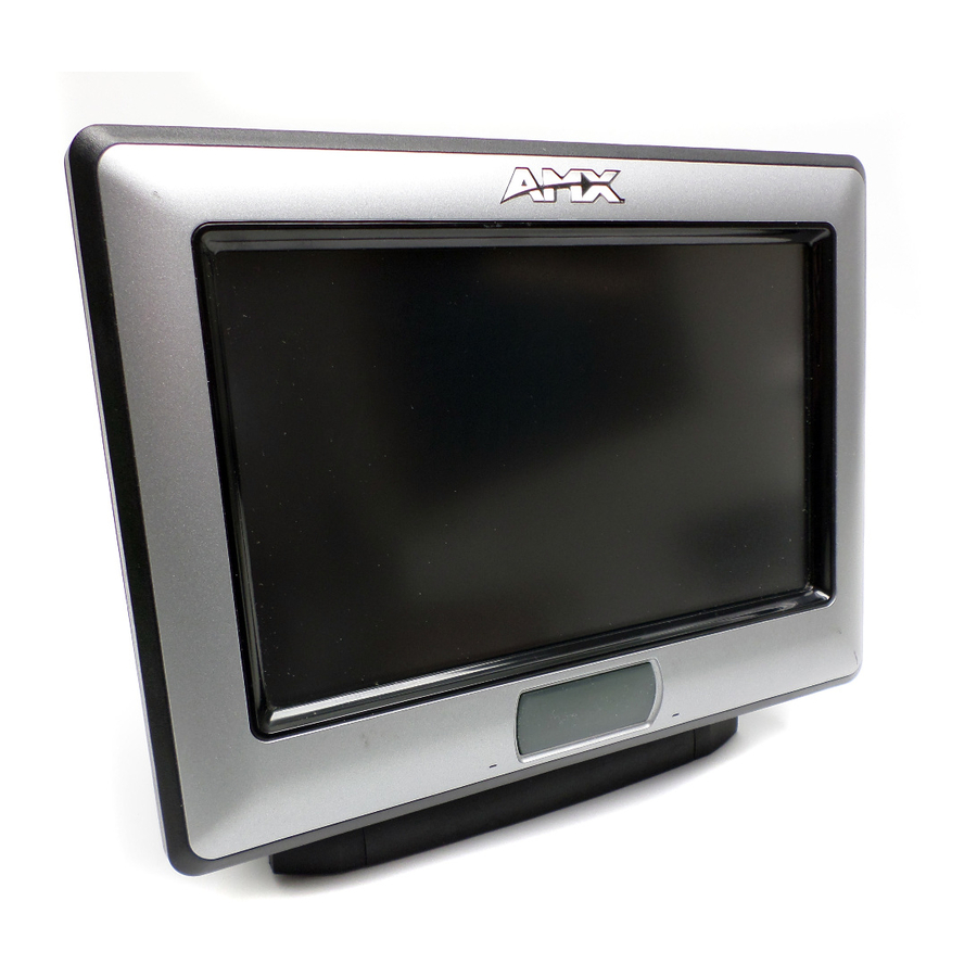
Introduction The NXT/D-CV7 7" Modero widescreen mini-touch panels and are available only through AMX. FIG. 1 Sample 7" Video Touch Panels These Color Video (CV) panels display NTSC/PAL/SECAM video formats within variable sized windows. They include a built-in microphone, speakers, audio/headphone connector, and six NetLinx pushbuttons (available on NXD models only when mounted with included Button Trim Ring). - Page 14 Key features common to both panels include: CV7 panels are based on the latest display technology and support AMX's 4th generation (G4) graphics which provide higher brightness, richer colors, and deeper contrast. The new G4 graphics technology is supported by the latest AMX TPDesign4 Touch Panel Design program (version 2.6 or higher).
-
Page 15: Cv7 Specifications
CV7 Specifications The following table outlines the specifications for the 7" Widescreen Modero panels. Specifications for 7" Widescreen Video Touch Panels Dimensions (HWD): Power Requirements (stand-alone CV7): Power Requirements (CV7 and BASE/1): Memory (factory default): Weight (stand-alone): Certifications: Panel LCD Parameters: Active Screen Area: IR Reception Angle: Supported Audio Sample... - Page 16 • The IR receiver is located beneath the translucent Front Setup button. When an IR code is detected it is sent to the NetLinx Master as a push on the appropriate AMX IR channel. • IR receivers and transmitters on G4 panels share the device address number of the panel.
- Page 17 - RackMount kit for 7" Wall Mount touch panels (NXD panels only). Kit includes eight #10-32 screws and washers. • NXA-WC80211GCF Wireless Upgrade Kit (FG2255-07) - AMX 802.11G Compact Flash provides wireless Ethernet support • NXT-BP (FG2255-10) - Battery pack for Table Top panels.
-
Page 18: Cv7 Panels - Connector Layout
Introduction CV7 Panels - Connector Layout FIG. 3 shows the layout of the connectors (located on the rear of the base on the NXT and on the left side panel of the NXD panels). Ethernet (CAT5) Stereo Output Mini-USB (Program) P RO G R AM NXT-CV7 - connectors located on rear panel of the base... -
Page 19: Cv7 Touch Panel Accessories
CV7 Touch Panel Accessories Overview The following section outlines and describes both the included accessories and other AMX equipment available for these touch panels. NXA-AVB/ETHERNET Breakout Box (FG2254-10) The NXA-AVB/ETHERNET Breakout Box (FIG. 4) is included as part of the CV7 Kit configuration (panel and box) but can be purchased as a separate accessory. -
Page 20: Installing The Nxa-Avb/Ethernet
CV7 Touch Panel Accessories NXA-AVB/ETHERNET Specifications (Cont.) Included Accessories: Other AMX Equipment: • AC-RK Accessory RackMount Kit (FG515) Installing the NXA-AVB/ETHERNET A 12 VDC-compliant power supply can indirectly provide power to a Modero panel by routing power through the NXA-AVB/ETHERNET Breakout Box. FIG. 5 shows a sample wiring configuration using both an indirect or direct power connection for a video-capable Modero panel. -
Page 21: Wiring The Nxa-Avb/Ethernet Connectors And Cables
Mic Out port. This signal can be fed as a Line Level In to either an amplifier or an AMX VOL card. Either a balanced (+, -, and GND) or unbalanced (+ and GND) audio signal can be connected to this output. -
Page 22: Wiring The Nxa-Avb/Ethernet For Unbalanced Audio
CV7 Touch Panel Accessories Wiring the NXA-AVB/ETHERNET for Unbalanced Audio Most domestic audio equipment has unbalanced audio inputs and outputs. This means that the audio output (left, right, or mono) appears on a single wire, and is referenced to "0 V" or "Ground". Typical connectors used are RCA "phono"... -
Page 23: Modero Table Top Cable (Ca2250-50)
Wiring information for the Modero Table Top cable If your installation requires custom cable configurations, you can purchase bulk (non-terminated) cable from Liberty Wire and Cable under the nomenclature "AMX Table Top Cable - Modero" (phone#: (800) 530 8998 or +1-719-388-7518). - Page 24 CV7 Touch Panel Accessories The following table provides the wiring information (color coding) for each of the three available cable connectors on each side of the Modero Table Top Cable. Modero Table Top Cable Wiring Table Wire Connector 1 White/Orange Orange/White White/Green Blue/White...
-
Page 25: Nxa-Wc80211B/Cf 802.11B Wireless Card (Fg2255-03)
Each bundle of 4 twisted pairs includes a colored tape indicator for identification. NXA-WC80211B/CF 802.11b Wireless Card (FG2255-03) These touch panels can connect to a wireless network using an optional AMX 802.11b Wireless Interface Card shown in FIG. 14. This internal card is field-upgradeable within both models of panels. -
Page 26: Nxa-Wc80211Gcf 802.11G Wireless Card (Fg2255-07)
This card works with compatible 802.11b/g Wireless Access Points such as the NXA-WAP200G (which uses a default SSID of AMX). Please follow your particular Wireless Access Point’s instruction manual for the correct procedures to setup either a secured or unsecured connection. The following table lists the specifications for the NXA-WC80211GCF. - Page 27 13: (Ch 1 - 13) - Japan (802.11g) 14: (Ch 1 - 14) - Japan (802.11b) Note: To alter the card’s default country code (North America), please contact an AMX Technical Support representative for detailed procedures and information. CV7 Touch Panel Accessories...
- Page 28 CV7 Touch Panel Accessories NXA-WC80211GCF Specifications (Cont.) Operating Environment: Operating Voltage: Power Consumption: Radio Data Rate: Radio Technology: Receiver Sensitivity: RF Frequency Ranges: Standard Conformance: Transmit Output Power: • Temperature: 0°C ~ 45°C (32°F to 113°F) (operating) and -20°C ~ 70°C (-4°F to 158°F) (storage) •...
-
Page 29: Nxa-Cfsp Compact Flash (Fg2116-3X)
Wireless LAN Security: Touch Panel Compatibility: Included Accessories: Other AMX Equipment: NXA-CFSP Compact Flash (FG2116-3x) Every CV7 Modero panel is shipped with a 64 MB Compact Flash card (NXA-CFSP). If possible, upgrade the panel’s internal components (Compact Flash or wireless interface cards) prior to installing or using the panel. -
Page 30: Before Upgrading The Wireless Card - Read This
These panels do not come factory installed with the NXA-WC802.11GCF wireless interface card. This card must be ordered separately from AMX as part of the 802.11g upgrade kit (FG2255-07). Do not use Ethernet cables containing mounting boots. These boots could make removal of the Ethernet connectors (from the panel) difficult and cumbersome. - Page 31 Phillips-head screwdriver to remove the two Tilt Bracket Screws (FIG. 17). This procedure both loosens the rear Tilt Bracket cover plate (with the AMX logo and Hinge brackets) and provides greater flexibility for the removal of the outer housing. Without this step, the Hinge brackets (FIG. 17) present an obstacle to the removal of the outer housing and restrict access to the circuit board.
-
Page 32: Step 2: Install The Compact Flash Memory Card Upgrade
CV7 Touch Panel Accessories Step 2: Install the Compact Flash Memory card upgrade Discharge any static electricity from your body by touching a grounded metal object and then locate the existing 64 MB Compact Flash card on the main board (FIG. 19). Front of panel Compact Flash Memory Card (Slot 1) -
Page 33: Step 3: Install The New 802.11G Cf Card And Antenna
Locate the two screw holes at either sides of the front speaker grill and then use a grounded Phillips-head screwdriver to both insert and secure the two Tilt Bracket Screws (FIG. 17). This procedure resecures the rear Tilt Bracket cover plate (with the AMX logo and Hinge brackets). 7" Modero Touch Panels... -
Page 34: Installation And Upgrade Of The Internal Nxd Components
NXD panel, as described in the following sections. These panels do not come factory installed with the NXA-WC802.11GCF wireless interface card. This card must be ordered separately from AMX as part of the 802.11g upgrade kit (FG2255-07). Step 1: Remove the existing NXD Outer Housing Carefully detach all connectors from the side of the touch panel and remove the Faceplate from the front of the panel. -
Page 35: Step 2: Install The New Compact Flash Memory Card (Nxd)
Wireless CF card (Slot #2 is located on the top slot) FIG. 23 Location of the wireless CF card connector on main board The circuit board comes pre-wired to internal speakers located on the inside surface of the rear back box. If the back box is removed incorrectly, these speaker wires can become disconnected and damaged. -
Page 36: Nxt-Bp Power Pack (Fg2255-10)
CV7 Touch Panel Accessories NXT-BP Power Pack (FG2255-10) The NXT-BP Power Pack (FIG. 24) is a rechargeable Lithium-Ion "smart" battery used to provide power to the NXT Modero panel through the NXA-BASE/1 Battery Base. This battery incorporates an on-board battery life indicator. -
Page 37: Checking The Nxt-Bp Charge
Operating / Storage Environment: Included Accessories: Other AMX Equipment: Before beginning the installation of the battery base to the Modero panel, verify the Modero panel has the latest firmware. Only the latest build incorporates the necessary updates for using the Modero with the NXA-BASE/1. From the Battery Base page, verify that the battery base is loaded with the latest NXA-BASE/1 firmware (v2.xx or higher). -
Page 38: Installing The Nxa-Base/1 Below An Nxt-Cv7 Panel
CV7 Touch Panel Accessories NXT-BP Battery FRONT FIG. 27 Battery installation Carefully insert the NXT-BP into the base until the battery securely fits onto the Battery Connector Port. Installing the NXA-BASE/1 below an NXT-CV7 Panel Power Off the panel before attempting to attach the NXA-BASE/1. Place the battery base (with battery) onto a flat/level surface. -
Page 39: Charging The Nxt-Bp Using The Nxa-Base/1
Slide the rear battery locking slider in the opposite direction. This turns the latching mechanism and secures the panel to the base. Upon successful connection, the AMX logo appears on the panel to indicate that the panel is properly connected and receiving power. -
Page 40: Nxt-Chg Battery Charger Kit (Fg2255-50K)
Dimensions (HWD): Power Requirements: Weight: Features: Other AMX Equipment: Powering the NXT-CHG Recalibration improves the reporting accuracy of the battery charge back to the Modero panel. The NXT-CHG Smart Battery Charger uses an included power supply to charge inserted batteries. -
Page 41: Reading The Nxt-Chg Led Indicator
Reading the NXT-CHG LED Indicator FIG. 31 shows the components on the NXT-CHG Smart Battery Charger. Slot 1 (recalibration) Slot 1 Recalibrate Pushbutton FIG. 31 Component locations on the NXT-CHG There is one LED indicator on the front of each battery slot that indicates the status of that slot. The blink patterns for these LEDs are described in the following table: •... - Page 42 CV7 Touch Panel Accessories 7" Modero Touch Panels...
-
Page 43: Installation
NXA-CFSP Compact Flash (FG2116-3x) section on page 17. Installing the No-Button Trim Ring The NXD-CV7 panel is shipped from AMX with the default Button Trim Ring already installed. The unit is also shipped with an included Trim Ring containing no button openings (a No-Button Trim Ring) that allows you, if desired, to change the default configuration of the NXD panel Faceplate to that with no-button openings. - Page 44 Installation Trim Ring Latches Default Button Trim Ring (with button openings) Faceplate (outside surface shown) FIG. 32 Removing the default Button Trim Ring 5. From along the internal surface of the Faceplate, remove the six buttons by gently bending each Button latch up and pulling the button outwards.
-
Page 45: Installing The Button Trim Ring
10. Place the Faceplate back onto the main NXD-CV7 unit. Make sure to align the Microphone, Light, and PIR Motion sensor locations on the main unit to their respective openings on the Faceplate assembly. Installing the Button Trim Ring The outer No-Button Trim Ring is secured to the Faceplate with plastic latches. In order to re-install the Button Trim Ring back onto an NXD panel which has had the default Button Trim Ring features removed;... -
Page 46: Pre-Wall Installation Of The Rough-In Box
Installation 8. Gently insert the Button Trim Ring latches into their corresponding openings on the outer surface of the internal Faceplate (FIG. 35). Button Trim Ring Button openings FIG. 35 Inserting the Button Trim RIng 9. Firmly press down around the Button Trim Ring until all of the latches are securely inserted into their openings on the Faceplate, and the Button Trim Ring is securely fastened. -
Page 47: Installation Of An Nxd Touch Panel
1. Rest the right Stud Mounting tabs onto the stud (keeping the knockouts on the left). Be sure to leave enough of a gap between the stud and NXD Mounting tabs to accommodate the installation of the drywall or sheetrock after the rough-in box has been mounted. Ultimately, the Mounting Tabs should lie flush against the outside of the sheetrock. - Page 48 Installation 1. Remove the Faceplate/bezel (A in FIG. 37) from the main NXD unit (B in FIG. 37) by gripping the faceplate and pulling with gentle outward force. #4-40 Mounting Screws (four - included) secure the NXD to the Rough-In Box FIG.
-
Page 49: Installing The Nxd Into Drywall Using Expansion Clips
8. Place the Faceplate/Trim Ring assembly (A in FIG. 37) back onto the main NXD unit (B in FIG. 37). Make sure to align the Microphone, Light, and PIR Motion sensor locations to their respective openings on the front faceplate/bezel. 9. - Page 50 Installation FIG. 38 NXD-CV7 Wall Mount panel dimensions using expansion clips 3. Remove the Faceplate/bezel (A in FIG. 39) from the main NXD unit (B in FIG. 39) by gripping the faceplate and pulling with gentle outward force. 4. Thread the incoming power, RJ-45, Ethernet, USB, and any optional audio/video wiring (from their terminal locations) through the surface opening.
- Page 51 9. Carefully insert the main unit (with expansion clips) into the cutout until the Mounting Tabs on the NXD unit lie flush against the wall. The drywall clip set must be re-ordered from AMX if the drywall clip is bent accidentally during an installation or removed during a re-installation.
-
Page 52: Installing The Nxd Into A Flat Surface Using #4 Screws
Installation 13. Reconnect the terminal power connector on the 12 VDC-compliant power supply and apply power. Installing the NXD into a Flat Surface using #4 screws Mounting screws (#4-40, included) are secured through two sets of circular holes located at the left and right sides of the NXD-CV7. - Page 53 Verify that the terminal end of the power cable is not connected to a power source before plugging in the 2-pin power connector. The USB connectors can be from a either a USB extension cable, or a wireless USB RF transmitter.
-
Page 54: Installing An Nxd-Cv7 Into An (Optional) Rack Mount Kit (Nxa-Rk7)
Installation 11. Reconnect the terminal RJ-45, Ethernet, USB, and any optional audio/video wiring to their respective locations on either the NXA-AVB/ETHERNET Breakout Box, Ethernet port, or NetLinx Master. 12. Reconnect the terminal power connector on the 12 VDC-compliant power supply and apply power. Installing an NXD-CV7 into an (optional) Rack Mount Kit (NXA-RK7) The NXA-RK7 is a 19"... -
Page 55: Wiring Guidelines For The Cv7 Panels
Wiring Guidelines for the CV7 Panels CV7 panels use a 12 VDC-compliant power supply to provide power to the panel via the 2-pin 3.5 mm mini-Phoenix PWR connector. Use the previously provided power requirement information to determine the power draw. The incoming PWR and GND wires from the power supply must be connected to the corresponding locations within the PWR connector. -
Page 56: Audio/Video Port: Connections And Wiring
Installation Audio/Video Port: Connections and Wiring The following table shows the signal and pinout/pairing information used on the RJ-45 Audio and Video connections. Audio/Video RJ-45 Pinout Information Wire Color Orange/White Orange Green/White Blue White/Blue Green White/Brown Brown 1 2 3 4 5 6 7 8 (female) RJ-45 connector - pin configurations Ethernet/RJ-45 Port: Connections and Wiring... -
Page 57: Usb Port: Connecting And Using Input Devices
The following table lists the pinouts, signals, and pairing associated with the Ethernet connector. Ethernet RJ-45 Pinouts and Signals Signals TX + TX - RX + no connection no connection RX - no connection no connection FIG. 44 diagrams the RJ-45 pinouts and signals for the Ethernet RJ-45 connector and cable. FIG. - Page 58 Installation 7" Modero Touch Panels...
-
Page 59: Panel Calibration
Modero panels are factory setup with specific demo touch panel pages. The first splash screen that appears indicates the panel is receiving power, beginning to load firmware, and preparing to display the default touch panel pages. When the panel is ready, the AMX Splash Screen is replaced by the Initial Panel Page (FIG. 45). -
Page 60: Testing Your Calibration
Panel Calibration FIG. 47 Touch Panel Calibration Screens 3. After the "Calibration Successful.." message appears, press anywhere on the screen to continue and return to the Setup page. If the calibration was improperly set and you cannot return to the Calibration page (through the panel’s firmware);... -
Page 61: Configuring Communication
(Ethernet) or through the use of the optional NXA-WC802.11GCF wireless CF card. Before commencing, verify you are using the latest NetLinx Master and Modero panel firmware. Verify you are using the latest versions of AMX’s NetLinx Studio and TPDesign4 programs. - Page 62 Configuring Communication 7. Press the on-screen Reboot button to restart the panel and incorporate any changes. FIG. 50 Protected Setup page Before continuing, open NetLinx Studio. This program assists in developing a System Number, Master IP/URL, and Master Port number. Refer to your NetLinx Master’s instruction manuals for more information.
-
Page 63: Configuring And Using Usb With A Virtual Master
Step 2: Confirm the Installation of the USB Driver on the PC The first time each AMX touch panel is connected to the PC it is detected as a new hardware device and the USBLAN driver becomes associated with it (panel specific). Each time thereafter the panel is "recognized"... - Page 64 Configuring Communication FIG. 52 USB System Settings page - using a USB Connection Type 5. Toggle the blue Type field (from the Master Connection section) until the choice cycles to USB. Refer to the System Settings Page section on page 130 for more information about the fields on this page.
-
Page 65: Step 3: Confirm And View The Current Amx Usb Device Connections
Within the Device Manager dialog, the AMX USBLAN device appears under Network Adapters (FIG. 54) and has a unique name such as AMX USB LAN LINK #2. The number changes depending on which recognized panel is currently connected. FIG. 54 Device Manager dialog showing USB device 3. -
Page 66: Step 4: Use The Usb To Configure A Virtual Master (Using Netlinx Studio)
To remove the USB driver association from a previously connected touch panel, you must navigate back to the Device Manager, right-click on the panel’s USB driver (example AMX USB LAN LINK #2) and select Uninstall from the context menu and then OK. - Page 67 3. Select Settings > Master Communication Settings, from the Main menu to open the Master Communication Settings dialog (FIG. 56). IP Address of computer (not needed as this is a direct USB connection) FIG. 56 Assigning Communication Settings for a Virtual Master 4.
-
Page 68: Step 5: Confirm And View The Current Amx Usb Device Connections
System sends out a request to the panel to respond and completes the communication (turning the System Connection icon green). Step 5: Confirm and View the current AMX USB device connections Use the CC-USB Type-A to Mini-B 5-wire programming cable (FG10-5965) to provide communication between the mini-USB Program port on the touch panel and the PC. -
Page 69: Wireless Settings Page - Wireless Access Overview
These touch panels allow users to connect to a wireless network through their use of the optional AMX 802.11g Wi-Fi CF card. The WAP communication parameters must match those of the pre-installed wireless interface card installed within the panel. -
Page 70: Step 1: Configure The Panel's Wireless Ip Settings
Configuring Communication Step 1: Configure the Panel’s Wireless IP Settings The first step to successfully setting up your internal wireless card is to configure the IP Settings section on the Wireless Settings page. The section configures the communication parameters from the Modero panel to the web. -
Page 71: Wireless Communication Using A Static Ip Address
Wireless communication using a Static IP Address 1. Press the Protected Setup button (located on the lower-left of the panel page) to open the Protected Setup page and display an on-screen keypad. 2. Enter 1988 into the Keypad’s password field and press Done when finished. 3. - Page 72 Configuring Communication FIG. 59 Site Survey page Access points are tracked by MAC Address. If the WAP’s SSID is set as a blank, then N/A is displayed within the SSID field. If the WAP’s SSID is hidden (not broadcast) it will not show up on the site survey ...
-
Page 73: Step 2: Configure The Card's Wireless Security Settings
In an Open security mode, when a target WAP is selected and the connect to, the SSID name of the selected WAP is saved for the open security mode. In a Static WEP security mode, when a WEP Access Point is selected and then connected to, the user is then redirected back to the Static WEP security screen where the SSID field is already filled out and the user is only required to enter in the remaining WEP key settings. - Page 74 The card should be given the SSID used by the target WAP. If this field is left blank, the unit will attempt to connect to the first available WAP. By default, all WAP200Gs use AMX as their assigned SSID value.
-
Page 75: Configuring The Modero's Wireless Card For Secured Access To A Wap200G
One of the most common problems associated with connection to a WAP arise because the SSID was not entered properly. You must maintain the same case when entering the SSID information. ABC is not the same as Abc. 10. Click Done when you’ve completed typing in the information. 11. - Page 76 Configuring Communication 802.11b wireless card FIG. 63 Wireless Settings page (showing how each card supports its own security features) You must first take down the SSID name, Current Key string value, and panel MAC Address information so you can later enter it into the appropriate WAP dialog fields in order to "sync-up"...
- Page 77 The card should be given the SSID used by the target WAP. If this field is left blank, the unit will attempt to connect to the first available WAP. By default, all WAP200Gs use AMX as their assigned SSID value.
- Page 78 Configuring Communication The code key generator on Modero panels use the same key generation formula. Therefore, this same Passphrase generates identical keys when done on any Modero because they all use the same Modero-specific generator. The Passphrase generator is case sensitive. 12.
-
Page 79: Configuring Multiple Wireless Moderos To Communicate To A Target Wap200G
If your target Wireless Access Point does not support passphrase key generation and has previously been setup with a manually entered WEP KEY, you must manually enter that same WEP key on your panel. 15. The remaining Current Key and Authentication fields are greyed-out and cannot be altered by the user. -
Page 80: Configuring A Wired Ethernet Connection
Configuring Communication Configuring a Wired Ethernet Connection It is necessary to tell the panel which Master it should be communicating with. This "pointing to a Master" is done via the System Settings page where you configure the IP Address, System Number and Username/Password information assigned to the target Master. -
Page 81: Step 2: Choose A Master Connection Mode Setting
2. Locate the IP Settings section of this page. Check with your System Administrator for a pre-reserved Static IP Address assigned to the panel. This address must be obtained before Static assignment of the panel continues. 3. Toggle the DHCP/Static field (from the IP Settings section) until the choice cycles to Static. 4. -
Page 82: Step 3: Configure An Ethernet Connection Type
Configuring Communication Step 3: Configure an Ethernet Connection Type When using Ethernet as your communication method, the NetLinx Master must first be setup with either a Static IP or DHCP Address obtained from either NetLinx Studio or your System Administrator. Before beginning: 1. -
Page 83: Master Connection Section - Virtual Master Communication Over Ethernet
1. Verify the panel has been configured to communicate either through an Ethernet cable (connected from either the panel to a valid Ethernet Hub) or wireless to the Wireless Access Point. 2. Launch NetLinx Studio 2.x (default location is Start > Programs > AMX Control Disc > NetLinx Studio 2 > NetLinx Studio 2). -
Page 84: Master Connection Section - Netlinx Master Ethernet Ip Address - Url Mode
By selecting URL, the System Number field becomes read-only (grey) because the panel pulls this value directly from the communicating target Master (virtual or not). A Virtual Master system value can be set within the active AMX software applications such as: NetLinx Studio, TPD4, or IREdit. -
Page 85: Master Connection Section - Netlinx Master Ethernet Ip Address - Listen Mode
If the panel does not appear within the OnLine Tree tab of the Workspace window of NetLinx Studio, check to make sure that the NetLinx Master System Number (from within the Device Addressing dialog) is correctly assigned. 3. Press the Master IP/URL field to open a Keyboard and enter the Master IP Address (obtained from the Diagnostics - Networking Address dialog of the NetLinx Studio application). -
Page 86: Master Connection Section - Netlinx Master Ethernet Ip Address - Auto Mode
Refer to the G4 Web Control Page section on page 101 for more detailed field information. Verify your NetLinx Master (ME260/64 or NI-Series) has been installed with the latest firmware KIT file from www.amx.com. Refer to your NetLinx Master instruction manual for more detailed information on the use of the new web-based NetLinx Security. - Page 87 2. Press the Protected Setup button (located on the lower-left of the panel page) to open the Protected Setup page and display an on-screen keypad. 3. Enter 1988 into the Keypad’s password field (1988 is the default password). Clearing Password #5, from the initial Password Setup page, removes the need for you to enter the default password before accessing the Protected Setup page.
-
Page 88: Using Your Netlinx Master To Control The G4 Panel
If the Master has been previously configured for secured communication, click OK to accept the AMX SSL certificate (if SSL is enabled) and then enter a valid username and password into the fields within the Login dialog. 4. Click OK to enter the information and proceed to the Master’s Manage WebControl Connections window. - Page 89 5. This Manage WebControl Connections page (FIG. 74) is accessed by clicking on the Manage connections link (within the Web Control section within the Navigation frame). Once activated, this page displays links to G4 panels running the latest G4 Web Control feature (previously setup and activated on the panel).
- Page 90 Configuring Communication Wired Ethernet - System Settings > IP Settings section within the IP Address field. Wireless - Wireless Settings > IP Settings section within the IP Address field. If you do not get this field continue to step 9. FIG.
-
Page 91: Upgrading Modero Firmware
Upgrading Modero Firmware Overview Before beginning the Upgrade process: Setup and configure your NetLinx Master. Refer to the your particular NetLinx Master Instruction Manual for detailed setup procedures. Calibrate and prepare the communication pages on the Modero panel for use. Refer to the Panel Calibration section on page 47. -
Page 92: Step 2: Prepare Netlinx Studio For Communication Via The Usb Port
8. Navigate back to the System Settings page. Step 2: Prepare NetLinx Studio for communication via the USB port 1. Launch NetLinx Studio 2.x (default location is Start > Programs > AMX Control Disc > NetLinx Studio 2 > NetLinx Studio 2). -
Page 93: Step 3: Confirm And Upgrade The Firmware Via The Usb Port
3. Click the Communications Settings button to open the Communications Settings dialog. 4. Click on the NetLinx Master radio button (from the Platform Selection section) to indicate that you are working as a NetLinx Master. 5. Click on the Virtual Master radio box (from the Transport Connection Option section) to indicate you are wanting to configure the PC to communicate directly with a panel. - Page 94 5. If the panel firmware being used is not current, download the latest Kit file by first logging in to www.amx.com and then navigate to Tech Center > Firmware Files and from within the Modero section of the web page locate your Modero panel.
-
Page 95: Upgrading The Modero Firmware Via Ethernet (Ip Address)
Note the IP Address and Gateway information. 2. Launch NetLinx Studio 2.x (default location is Start > Programs > AMX Control Disc > NetLinx Studio 2 > NetLinx Studio 2). 3. Select Settings > Master Communication Settings from the Main menu to open the Master Communication Settings dialog (FIG. - Page 96 Upgrading Modero Firmware FIG. 80 Assigning Master Communication Settings and TCP/IP Settings 9. Place a checkmark within the Automatically Ping the Master Controller to ensure availability radio box to make sure the Master is initially responding online before establishing full communication. 10.
-
Page 97: Step 2: Prepare The Panel For Communication Via An Ip
By selecting URL, the System Number field becomes read-only (grey) because the panel pulls this value directly from the communicating target Master (virtual or not). A Virtual Master system value can be set within the active AMX software applications such as: NetLinx Studio, TPD4, or IREdit. - Page 98 Upgrading Modero Firmware Selected Firmware file FIG. 81 Send to NetLinx Device dialog (showing Modero firmware update via IP) 7. Select the panel’s Kit file from the Files section (FIG. 81). 8. Enter the Device value associated with the panel and the System number associated with the Master (listed in the OnLine Tree tab of the Workspace window).
-
Page 99: Firmware Pages And Descriptions
Firmware Pages and Descriptions This section describes each firmware page and their specific functional elements. Setup Navigation Buttons These Setup Navigation Buttons (FIG. 82) appear on the left of the panel screen when the Setup page is currently active. Modero Setup Navigation Buttons FIG. -
Page 100: Setup Page
Firmware Pages and Descriptions Setup Navigation Button Elements (Cont.) Protected Setup: Video Adjustment: Battery Base: Setup Page This page (FIG. 83) centers around basic Modero panel properties such as: Connection Status of the panel, Display Timeout, Inactivity Page Flip Time, Inactivity page file, and the Panel Brightness. FIG. - Page 101 Setup Page Elements (Cont.) Connection Status: Display/Panel Timeout: Inactivity Page Flip Timeout: Panel Brightness: 7" Modero Touch Panels Displays whether the panel is communicating externally, the encryption status of the communicating Master, what connection type is being used (Ethernet or USB), and what System the panel is a part of.
-
Page 102: Project Information Page
Sales Order: Purchase Order: AMX IR 38k Assigned Port: Displays the AMX 38 kHz IR channel port used by the IR receiver on the panel. Returns you to the previously active touch panel page. This visual display of the connection status allows the user to have a current visual update of the panel’s connection status regardless of what page is... -
Page 103: Panel Information Page
Panel Type: Firmware Version: 7" Modero Touch Panels Displays the AMX 455 kHz IR channel port used by the IR receiver on the panel. This information is pulled by the panel from AMX IR Receivers section of the TPD4 Project Properties > IR Emitters & Receivers tab. -
Page 104: Time & Date Setup Page
Firmware Pages and Descriptions Panel Information Page Elements (Cont.) Setup Port: High Port: High Address: High Channel: High Level: Serial Number: Setup Pages Version: Screen Width: Screen Height: Screen Refresh Rate: Screen Rotation: Power Up Pages: Start Up String: Wake Up String: Sleep String: File System: RAM:... - Page 105 The only way to modify a panel’s time, without altering the Master, is to use NetLinx Code. The elements of the Time & Date Setup page are described in the table below: Time & Date Setup Page Elements Back: Connection Status icon: Time Date Refresh/Set: Time Display fields: Date Display fields:...
-
Page 106: Volume Page
Firmware Pages and Descriptions Volume Page The Volume page (FIG. 87) (accessed by pressing the Audio Adjustments button on the Setup page) allows you to adjust the master volume parameters and default panel sounds on the panel. FIG. 87 Volume configuration page The elements of the Volume page are described in the table below: Volume Page Elements Back:... -
Page 107: Supported Sampling Rates For Wav
Volume Page Elements (Cont.) Analog/Breakout Box: Line In Level: Mic Out Level: Supported sampling rates for WAV The following is a listing of supported sampling rates associated for WAV files played on CV7 panels. Some WAV files currently played on Modero's may not work on these panels. The supported sampling rates for WAV files are: Supported WAV Sampling Rates •... -
Page 108: Battery Base Page
Firmware Pages and Descriptions The elements of the Video Setup page are described in the table below: Video Setup Page Elements Back: Connection Status icon: Settings: Video Settings: Status: Format: Brightness: Contrast: Saturation: Hue: Battery Base Page This page (FIG. 89) allows you to alter/set the power warning preferences, monitor battery status information, and alter the display times for the battery warnings. - Page 109 FIG. 89 Battery Base page Battery Base Page Elements Back: Connection Status icon: Charge Status: Panel Shutdown: Low Battery Warning: Very Low Battery Warning: The Very Low Battery Warning UP/DN buttons alter the time value 7" Modero Touch Panels Saves the changes and returns you to the previously active touch panel page. This visual display of the connection status allows the user to have a current visual update of the panel’s connection status regardless of what page is currently active.
-
Page 110: Protected Setup Navigation Buttons
Firmware Pages and Descriptions Battery Base Page Elements (Cont.) Battery Status fields: Battery Power Brightness Limit: The term "quality" (in the context of a battery), refers to the current capacity relative to the batteries’ rated capacity. For example, after constant use, a battery may be operating at 75% of its rated capacity even though it might be fully charged. -
Page 111: Protected Setup Page
These Navigation Buttons are specific to these Modero panels and include panel specific elements described in the following table: Protected Setup Navigation Button Elements G4 Web Control: Sensors: Passwords: Calibrate: Wireless Settings: System Settings: Protected Setup Page The Protected Setup page (FIG. 91) centers around the properties used by the panel to properly communicate with the NetLinx Master. - Page 112 • The Remove User Pages button allows you remove all current TPD4 touch panel pages currently on the panel (including the pre-installed AMX Demo pages). - Pressing this button launches a Confirmation dialog (FIG. 92) which asks you to confirm your selection.
-
Page 113: G4 Web Control Page
FIG. 92 Protected Setup page-System Recovery confirmation dialog Channel Port 3,132 Level Port Channel Code Number FIG. 93 Button/slider Function Show example G4 Web Control Page The G4 Web Control page (FIG. 94) centers around enabling and disabling both the display and control of your panel (via the web). - Page 114 Firmware Pages and Descriptions The elements of the G4 Web Control page are described in the table below: G4 Web Control Page Elements Back: Connection Status icon: G4 Web Control Settings: Enable/Enabled Network Interface Select Web Control Name Web Control Password Web Control Port Maximum Number of Connections...
-
Page 115: Sensor Setup Page Elements
FIG. 95 Sample relationship between G4 Web Control and Mange WebControl Connections window Sensor Setup The Sensor Setup page (FIG. 96) allows you to adjust the Light and Motion Sensor parameters on a Modero touch panel. FIG. 96 Sensor Setup page A light level value between the Minimum and Maximum DIM Mode values delivers an average light level. - Page 116 Firmware Pages and Descriptions Sensor Setup Page Elements (Cont.) Light Sensor: Dim Mode Minimum Brightness: Motion Sensor: Allows you to monitor and alter the sensitivity of the Modero panel light sensor: • The Light Sensor Level field indicates the level used to report the light sensor level back to the NetLinx Master (set in TPD4) (read-only).
-
Page 117: Making The Most Of The Automated Brightness Control Feature (Dim Mode)
Sensor Setup Page Elements (Cont.) Wake Panel On Motion Sense: There is a relationship between the motion sensor and the panel sleep feature. If a panel is set to Sleep Mode, there is a time delay before the motion sensor is activated to detect motion. -
Page 118: Password Setup Page
Firmware Pages and Descriptions 9. Set the Minimum brightness of the Dimmer (Dim Mode Max Level) below the detected drop. This will make sure that the panel does not react to variations in the lighting conditions of a normal working environment. The minimum (lower level) of the dimmer should be at least 10% lower than the minimum detected level (ex: lower dimmer level at 30% if the detected lighting of the room is at 40%). -
Page 119: Calibration Page
Calibration Page This page (FIG. 98) allows you to calibrate the touch panel using a pre-selected touch driver. Press and hold the grey Front Setup Access button (below the Modero LCD) for 6 seconds to access the Calibration page. ... - Page 120 Firmware Pages and Descriptions Wireless Security Support 802.11b Wi-Fi CF card: 802.11g Wi-Fi CF card: Refer to the Configuring a Wireless Connection section on page 57 for more detailed information of setting up the MVP panel for wireless network access using the different types of security options. FIG.
- Page 121 Wireless Settings Page Elements (Cont.) IP Settings: DHCP/STATIC IP Address Subnet Mask Gateway Host Name Primary DNS Secondary DNS Domain MAC Address Access Point MAC Address: 7" Modero Touch Panels Sets the IP communication values for the touch panel and contains: Sets the panel to either DHCP or Static communication modes.
- Page 122 Firmware Pages and Descriptions Wireless Settings Page Elements (Cont.) Wireless Security: Open (Clear Text) Static WEP WPA-PSK Sets the wireless security method being used by the Modero panel to establish communication with the network (via the target WAP). • Touching any of the eight available connection method buttons launches a new connection-specific dialog page which allows the user to define the communication parameters specific to that type of connection.
- Page 123 • Refer to the following Wireless Settings Page - Security Options - Overview section on page 113 for further details on these security options. • For more information on uploading a certificate file, refer to the AMX Certificate Upload Utility section on page 195.
- Page 124 Firmware Pages and Descriptions Wireless Settings Page Elements (Cont.) Wireless Security (Cont.): EAP-FAST Site Survey: RF Link Info: SSID Channel Link Quality Signal Strength Data Rate An EAP-FAST security method is designed for wireless environments where both security and ease of setup are balanced together. •...
-
Page 125: Wireless Settings Page - Security Options - Overview
- The card should be given the SSID used by the target WAP. - If this field is left blank, the unit will attempt to connect to the first available WAP. By default, all WAP200Gs use AMX as their assigned SSID value. -
Page 126: Wireless Settings Page - Security Options - Static Wep
Firmware Pages and Descriptions Wireless Settings Page - Security Options - Static WEP A Static WEP security method requires that both a target WAP be identified and an encryption method be implemented prior to establishing an active communication session. In addition to providing both Open and Shared Authentication capabilities, this page also supports Hexadecimal and ASCII keys. - Page 127 Entering the same apple in the Passphrase generator of any Modero panel generates a different key: a1:b2:c3:d4:etc. Only AMX Modero panels generate the same Current Key by using a unique Passphrase key generation technology. A Current Key string, when generated anywhere else, will not match those created on the Modero panels.
-
Page 128: Wireless Settings Page - Security Options - Wpa-Psk
Firmware Pages and Descriptions Wireless Security - Static WEP (Cont.) Current Key: Authentication: Save/Cancel: Wireless Settings Page - Security Options - WPA-PSK A WPA-PSK security method is designed for environments where its desirable to use WPA or WPA2 but an 802.1x authentication server is not available. PSK connections are more secure than WEP and are simpler to configure since they implement dynamic keys but share a key between the WAP and the panel (client). -
Page 129: Wireless Settings Page - Security Options - Eap-Leap
Wireless Security - WPA-PSK Settings SSID (Service Set Identifier): Password/Pass Phrase: Save/Cancel: Wireless Settings Page - Security Options - EAP-LEAP EAP (Extensible Authentication Protocol) is a Enterprise authentication protocol that can be used in both a wired and wireless network environment. EAP requires the use of an 802.1x Authentication Server, also known as a Radius server. - Page 130 This works in tandem with the Password string which is similar to the password entered to gain access to a secured workstation. Note: Typically, this is in the form of a username such as: jdoe@amx.com • Use the on-screen keyboard’s Clear button to completely erase any previously stored identity/username information.
-
Page 131: Wireless Settings Page - Security Options - Eap-Fast
Wireless Security - EAP-LEAP Settings (Cont.) Save/Cancel: FIG. 105 EAP-LEAP sample Cisco System Security page Wireless Settings Page - Security Options - EAP-FAST EAP (Extensible Authentication Protocol) is a Enterprise authentication protocol that can be used in both a wired and wireless network environment. EAP requires the use of an 802.1x Authentication Server, also known as a Radius server. - Page 132 This works in tandem with the Password string which is similar to the password entered to gain access to a secured workstation. Note: Typically, this is in the form of a username such as: jdoe@amx.com • Use the on-screen keyboard’s Clear button to completely erase any previously stored identity/username information.
- Page 133 PAC shared secret credentials for use in authentication. In this case, the IT department must create a PAC file and then transfer it into the panel using the AMX Certificate upload application. This field is used when the previous Automatic PAC Provisioning option has been Disabled.
-
Page 134: Eap Security's Using Server Certificates - Overview
Firmware Pages and Descriptions EAP Security’s Using Server Certificates - Overview The following EAP types all support a server certificate: EAP-PEAP EAP-TTLS EAP-TLS All three of these certificate-using security methods are documented in the following sections. EAP Authentication goes a step beyond just encrypting data transfers, but also requires that a set of credentials be validated before the client (panel) is allowed to connect to the rest of the network (FIG. - Page 135 There are two main versions of the PEAP protocol supported by panel’s DeviceScape Wireless Client are: PEAPv0 (developed with Microsoft) PEAPv1 (developed exclusively by Cisco) PEAP uses an inner authentication mechanism which is supported by the DeviceScape Wireless Client, the most common of which are: MSCHAPv2 with PEAPv0 and ...
-
Page 136: Wireless Settings Page - Security Options - Eap-Ttls
This works in tandem with the Password string which is similar to the password entered to gain access to a secured workstation. Note: Typically, this is in the form of a username such as: jdoe@amx.com • Use the on-screen keyboard’s Clear button to completely erase any previously stored identity/username information. - Page 137 TTLS (EAP Tunneled Transport Layer Security) was an authentication method, like PEAP, that does not use a client certificate to authenticate the panel. This method is more secure than PEAP in that it does not broadcast the identity of the user. The setup, although similar to PEAP, differs in the following areas: ...
- Page 138 This works in tandem with the Password string which is similar to the password entered to gain access to a secured workstation. Note: Typically, this is in the form of a username such as: jdoe@amx.com • Use the on-screen keyboard’s Clear button to completely erase any previously stored identity/username information.
-
Page 139: Wireless Settings Page - Security Options - Eap-Tls
Wireless Settings Page - Security Options - EAP-TLS EAP (Extensible Authentication Protocol) is a Enterprise authentication protocol that can be used in both a wired and wireless network environment. EAP requires the use of an 802.1x Authentication Server, also known as a Radius server. Most of the configuration fields described below take variable length strings as inputs. - Page 140 This works in tandem with the Password string which is similar to the password entered to gain access to a secured workstation. Note: Typically, this is in the form of a username such as: jdoe@amx.com • Use the on-screen keyboard’s Clear button to completely erase any previously stored identity/username information.
-
Page 141: Client Certificate Configuration
Format is: PKCS12 First file contains the client certificate and the second file contains the private key. Format is: PKCS12 AMX supports the following security certificates within three different formats: PEM (Privacy Enhanced Mail) DER (Distinguished Encoding Rules) ... -
Page 142: System Settings Page
Firmware Pages and Descriptions It is important to note which certificate types are supported by the different certificate fields used on the configuration screens (PEAP, TTLS, and TLS). The following table outlines the firmware fields and their supported certificate types. Certificate Types Supported by the Modero Firmware Configuration Field Name Certificate Authority field... - Page 143 Sets the speed of the Ethernet connection to the panel. • Choices are: Auto, 10 Half Duplex, 10 Full Duplex, 100 Half Duplex, or 100 Full Duplex. Displays a read-only field that is factory set by AMX for the built-in Ethernet interface. Sets the NetLinx Master communication values: Sets the NetLinx Master to communicate with the panel via either USB or Ethernet.
- Page 144 Firmware Pages and Descriptions System Settings Page Elements (Cont.) Master Connection (Cont.): System Number Master IP/URL Master Port Number Username/Password Refer to the Step 2: Choose a Master Connection Mode Setting section on page 69 for more detailed information on using the System Settings page. Allows you to enter a system number.
-
Page 145: Programming
Programming Overview You can program the touch panel, using the commands in this section, to perform a wide variety of operations using Send_Commands and variable text commands. A device must first be defined in the NetLinx programming language with values for the Device: Port: System (in all programming examples - Panel is used in place of these values and represents all Modero panels). -
Page 146: Cpg
Programming Page Commands (Cont.) @CPG Syntax: Clear all popup pages from Variable: specified popup group. Example: Clears all popup pages from the popup group ’Group1’. @DPG Syntax: Delete a specific popup page from Variable: specified popup group if it exists. Example: Deletes the popup page ’Popup1’... -
Page 147: Pht
Page Commands (Cont.) @PHT Syntax: Set the hide effect "'@PHT-<popup page name>;<hide effect time>'" time for the Variable: specified popup popup page name = 1 - 50 ASCII characters. Name of the page the popup is displayed page. hide effect time = Given in 1/10ths of a second. Example: SEND_COMMAND Panel,"'@PHT-Popup1;50'"... -
Page 148: Ppk
Programming Page Commands (Cont.) @PPK Kill refers to the deactivating (Off) of a popup window from all pages. If the pop-up page is part of a group, the whole group is deactivated. This command works in the same way as Kill a specific the 'Clear Group' command in TPDesign 4. -
Page 149: Ppx
Page Commands (Cont.) @PPX This command works in the same way as the 'Clear All' command in TPDesign 4. Close all Syntax: popups on all "'@PPX'" pages. Example: SEND_COMMAND Panel,"'@PPX'" Close all popups on all pages. @PSE Syntax: Set the show "'@PSE-<popup page name>;<show effect name>'"... -
Page 150: Ppof
Programming Page Commands (Cont.) PPOF If the page name is empty, the current page is used (see example 2). If the popup page is part of a group, the whole group is deactivated. This command works in the same way as Deactivate a the ’Hide Popup’... -
Page 151: Programming Numbers
Programming Numbers The following information provides the programming numbers for colors, fonts, and borders. Colors can be used to set the colors on buttons, sliders, and pages. The lowest color number represents the lightest color-specific display; the highest number represents the darkest display. For example, 0 represents light red, and 5 is dark red. - Page 152 Programming RGB Values for all 88 Basic Colors (Cont.) Index No. Name Very Dark Aqua Very Light Blue Light Blue Blue Medium Blue Dark Blue Very Dark Blue Very Light Purple Light Purple Purple Medium Purple Dark Purple Very Dark Purple Very Light Magenta Light Magenta Magenta...
-
Page 153: Font Styles And Id Numbers
The TPDesign4 Touch Panel Design program has pre-set border styles that are user selectable. TPD4 border styles can ONLY be changed by using the name. Border styles None AMX Elite -L AMX Elite -M AMX Elite -S Bevel -L Bevel -M... - Page 154 Programming Border styles Circle 125 Circle 135 Circle 145 Circle 155 Circle 165 Circle 175 Circle 185 Circle 195 Diamond 185 Diamond 195 Double Bevel -L Double Bevel -M Double Bevel -S Double Line Fuzzy Glow-L Glow-S Help Down Neon Active -L Neon Active -S Neon Inactive -L Neon Inactive -S...
- Page 155 Border styles Menu Bottom Rounded 105 Menu Bottom Rounded 115 Menu Bottom Rounded 125 Menu Bottom Rounded 135 Menu Bottom Rounded 145 Menu Bottom Rounded 155 Menu Bottom Rounded 165 Menu Bottom Rounded 175 Menu Left Rounded 55 Menu Left Rounded 65 Menu Left Rounded 75 Menu Left Rounded 85 Menu Left Rounded 95...
-
Page 156: Button Commands
Programming "^" Button Commands These Button Commands are used in NetLinx Studio and are case insensitive. All commands that begin with "^" have the capability of assigning a variable text address range and button state range. A device must first be defined in the NetLinx programming language with values for the Device: Port : System (in all programming examples - Panel is used in place of these values). -
Page 157: Bau
"^" Button Commands (Cont.) ^BAU Same format as ^UNI. Append Syntax: unicode text. "'^BAU-<vt addr range>,<button states range>,<unicode text>'" Variable: variable text address range = 1 - 4000. button states range = 1 - 256 for multi-state buttons (0 = All states, for General buttons 1 = Off state and 2 = On state). -
Page 158: Bct
Programming "^" Button Commands (Cont.) ^BCT Only if the specified text color is not the same as the current color. Set the text color Note: Color can be assigned by color name (without spaces), number or R,G,B value to the specified (RRGGBB or RRGGBBAA). -
Page 159: Bim
"^" Button Commands (Cont.) ^BIM Syntax: Set the input "'^BIM-<vt addr range>,<input mask>'" mask for the Variable: specified address. variable text address range = 1 - 4000. input mask = Refer to the Text Area Input Masking section on page 184 for character types. -
Page 160: Bmc
Programming "^" Button Commands (Cont.) ^BMC Note that the source is a single button state. Each state must be copied as a separate command. The <codes> section represents what attributes will be copied. All codes are Button copy 2 char pairs that can be separated by comma, space, percent or just ran together. command. -
Page 161: Bmf
"^" Button Commands (Cont.) ^BMF Syntax: Set any/all button "'^BMF-<vt addr range>,<button states range>,<data>'" parameters by Variables: sending variable text address char array = 1 - 4000. embedded codes button states range = 1 - 256 for multi-state buttons (0 = All states, for General buttons and data. -
Page 162: Bmi
Programming "^" Button Commands (Cont.) ^BMF (Cont.) Example: Sets the button OFF state as well as the Border, Fill Color, Border Color, Text Color, and Bitmap. ^BMI Mask image is used to crop a borderless button to a non-square shape. This is typically used with a bitmap. -
Page 163: Bml
"^" Button Commands (Cont.) ^BML If this value is set to zero (0) there is no max length. The maximum length available is 2000. This is only for a Text area input button and not for a Text area input masking button. Set the maximum length of the text Syntax:... -
Page 164: Bop
Sets the border by number (#10) to those buttons with the variable text range of 500-504 & 510-515. Sets the border by name (AMX Elite) to those buttons with the variable text range of 500-504 & 510-515. The border style is available through the TPDesign4 border-style drop-down list. Refer to theTPD4 Border Styles by Name table on page 141 for more information. -
Page 165: Bpp
^BPP Zero clears the flag. Set or clear the Syntax: protected page flip "'^BPP-<vt addr range>,<protected page flip flag value>'" flag of a Variable: button. variable text address range = 1 - 4000. protected page flip flag value range = 0 - 4 (0 clears the flag). Example: SEND_COMMAND Panel,"'^BPP-500,1'"... -
Page 166: Bso
Programming ^BSO If the sound name is blank the sound is then cleared. If the sound name is not matched, the button sound is not changed. Set the sound played when a Syntax: button is pressed. Variable: Example: Assigns the sound 'music.wav' to the button Off/On states. ^BSP Set the button size and its position on the page. -
Page 167: Bvt
^BVT Syntax: Set the computer "'^BVT-<vt addr range>,<network port>'" control network Variable: port for the speci- variable text address range = 1 - 4000. fied address. network port = 1 - 65535. Example: SEND_COMMAND Panel,"'^BVT-500,5000'" Sets the network port to 5000. ^BWW By default, word-wrap is Off. -
Page 168: Ena
Programming ^ENA Syntax: Enable or disable buttons Variable: with a set variable text range. Example: Disables button pushes on buttons with variable text range 500-504 & 510-515. ^FON Font ID numbers are generated by the TPDesign4 programmers report. Set a font to a Syntax: specific Font ID value for those... -
Page 169: Glh
^GLH Syntax: Change the "'^GLH-<vt addr range>,<bargraph hi>'" bargraph upper Variable: limit. variable text address range = 1 - 4000. bargraph limit range = 1 - 65535 (bargraph upper limit range). Example: SEND_COMMAND Panel,"'^GLH-500,1000'" Changes the bargraph upper limit to 1000. ^GLL Syntax: Change the... -
Page 170: Gsn
Programming ^GSN Slider names and cursor names can be found in the TPDesign4 slider name and cursor drop-down list. Change the bargraph slider Syntax: name or joystick cursor name. Variable: Example: Changes the bargraph slider name or the Joystick cursor name to ’Ball’. ^ICO Syntax: Set the icon to a... -
Page 171: Jsb
^JSB The alignment of 0 is followed by ',<left>,<top>'. The left and top coordinates are relative to the upper left corner of the button. Set bitmap/ picture alignment Syntax: using a numeric "'^JSB-<vt addr range>,<button states range>,<new text keypad layout for alignment>'"... -
Page 172: Jst
Programming ^JST The alignment of 0 is followed by ',<left>,<top>'. The left and top coordinates are relative to the upper left corner of the button. Set text alignment using a Syntax: numeric keypad layout for those buttons with a Variable: defined address range. -
Page 173: Skt
^SKT Syntax: Receive touch '^SKT-<0=disable socket, greater than 1023=enable socket on information on specified port> specified socket. Only socket values equal to or greater than 1024 are valid. The panel will open up a TCP listening socket on the port specified. User or 3rd party program can connect to the panel using this port/socket number and receive touch/release/move strings. -
Page 174: Text Effect Names
Programming ^UNI For the ^UNI command (%UN and ^BMF command), the Unicode text is sent as ASCII-HEX nibbles. Set Unicode text. Syntax: Variable: Example: Sets the button’s unicode character to ’A’. Note: To send the variable text ’A’ in unicode to all states of the variable text button 1, (for which the character code is 0041 Hex), send the following command: Note: Unicode is always represented in a HEX value. -
Page 175: Button Query Commands
Button Query Commands Button Query commands reply back with a custom event. There will be one custom event for each button/state combination. Each query is assigned a unique custom event type. The following example is for debug purposes only: NetLinx Example: CUSTOM_EVENT[device, Address, Custom event type] DEFINE_EVENT CUSTOM_EVENT[TP,529,1001] CUSTOM_EVENT[TP,529,1002]... -
Page 176: Bcb
Programming Button Query Commands ?BCB Syntax: Get the current border color. Variable: Example: Gets the button 'OFF state' border color. information. The result sent to the Master would be: ?BCF Syntax: Get the current fill color. Variable: Example: Gets the button 'OFF state' fill color information. The result sent to the Master would be: "'?BCB-<vt addr range>,<button states range>'"... -
Page 177: Bct
Button Query Commands (Cont.) ?BCT Syntax: Get the current "'?BCT-<vt addr range>,<button states range>'" text color. Variable: variable text address range = 1 - 4000. button states range = 1 - 256 for multi-state buttons (0 = All states, for General buttons 1 = Off state and 2 = On state). -
Page 178: Bop
Programming Button Query Commands (Cont.) ?BOP Syntax: Get the overall button opacity. Variable: Example: Gets the button 'OFF state' opacity information. The result sent to the Master would be: ?BRD Syntax: Get the current border name. Variable: Example: Gets the button 'OFF state' border information. The result sent to the Master would be: "'?BOP-<vt addr range>,<button states range>'"... -
Page 179: Bww
Button Query Commands (Cont.) ?BWW Syntax: Get the current "'?BWW-<vt addr range>,<button states range>'" word wrap flag Variable: status. variable text address range = 1 - 4000. button states range = 1 - 256 for multi-state buttons (0 = All states, for General buttons 1 = Off state and 2 = On state). -
Page 180: Ico
Programming Button Query Commands (Cont.) ?ICO Syntax: Get the current icon index. Variable: Example: Gets the button 'OFF state' icon index information. The result sent to the Master would be: ?JSB Syntax: Get the current bitmap Variable: justification. Example: Gets the button 'OFF state' bitmap justification information. The result sent to the Master would be: "'?ICO-<vt addr range>,<button states range>'"... -
Page 181: Jsi
Button Query Commands (Cont.) ?JSI Syntax: Get the current "'?JSI-<vt addr range>,<button states range>'" icon Variable: justification. variable text address range = 1 - 4000. button states range = 1 - 256 for multi-state buttons (0 = All states, for General buttons 1 = Off state and 2 = On state). -
Page 182: Tec
Programming Button Query Commands (Cont.) ?TEC Syntax: Get the current text effect color. Variable: Example: Gets the button 'OFF state' text effect color information. The result sent to the Master would be: ?TEF Syntax: Get the current text effect name. Variable: Example: Gets the button 'OFF state' text effect name information. -
Page 183: Panel Runtime Operations
Button Query Commands (Cont.) ?TXT Syntax: Get the current "'?TXT-<vt addr range>,<button states range>,<optional index>'" text information. Variable: variable text address range = 1 - 4000. button states range = 1 - 256 for multi-state buttons (0 = All states, for General buttons 1 = Off state and 2 = On state). -
Page 184: Akb
Programming Panel Runtime Operation Commands (Cont.) @AKB Keyboard string is set to null on power up and is stored until power is lost. The Prompt Text is optional. Pop up the keyboard icon and Syntax: initialize the text string to that Variables: specified. -
Page 185: Akr
Panel Runtime Operation Commands (Cont.) @AKR Remove keyboard or keypad that was displayed using 'AKEYB', 'AKEYP', 'PKEYP', @AKB, @AKP, @PKP, @EKP, or @TKP commands. Remove the Keyboard/ Syntax: Keypad. "'@AKR'" Example: SEND COMMAND Panel,"'@AKR'" Removes the Keyboard/Keypad. BEEP Syntax: Output a beep. "'BEEP'"... -
Page 186: Pkeyp
Programming Panel Runtime Operation Commands (Cont.) PKEYP Pops up the keypad icon and initializes the text string to that specified. Keypad displays a '*' instead of the numbers typed. The Prompt Text is optional. Present a private keypad. Syntax: Variables: Example: Pops up the Keypad and initializes the text string '123456789' in '*'. -
Page 187: Tkp
Panel Runtime Operation Commands (Cont.) @TKP Pops up the keypad icon and initializes the text string to that specified. The Prompt Text is optional. Present a telephone Syntax: keypad. "'@TKP-<initial text>;<prompt text>'" Variables: initial text = 1 - 50 ASCII characters. prompt text = 1 - 50 ASCII characters. -
Page 188: Input Commands
Programming Input Commands These Send Commands are case insensitive. Input Commands ^CAL Syntax: Put panel in calibration mode. Example: Puts the panel in calibration mode. ^KPS Syntax: Set the keyboard Variable: passthru. Example: Sets the keyboard passthru to the Master. Option 5 sends keystrokes directly to the Master via the Send Output String mechanism. -
Page 189: Embedded Codes
Embedded codes The following is a list of G4 compatible embedded codes: Embedded Codes Decimal numbers Hexidecimal values 7" Modero Touch Panels Virtual keystroke ($08) Backspace ($0D) Enter ($1B) ($80) CTRL key down ($81) ALT key down ($82) Shift key down ($83) ($84) ($85) -
Page 190: Panel Setup Commands
Programming Panel Setup Commands These commands are case insensitive. Panel Setup Commands ^MUT Syntax: Set the panel mute state. Variable: Example: Sets the panel’s master volume to mute. @PWD @PWD sets the level 1 password only. Set the page flip Syntax: password. -
Page 191: Dynamic Image Commands
Adds a new resource. • The resource name is ’New Image’ • %P (protocol) is an HTTP • %H (host name) is AMX.COM • %A (file path) is Lab/Test_file • %F (file name) is test.jpg. Note that the %%5F in the file path is actually encoded as %5F. -
Page 192: Raf, ^Rmf - Embedded Codes
Programming Dynamic Image Commands (Cont.) ^RMF Modifies any and all resource parameters by sending embedded codes and data. Since the embedded codes are preceded by a '%' character, any '%' character contained Modify an in the URL must be escaped with a second '%' character (see example). existing resource. -
Page 193: Escape Sequences
Channel port Level code Level port X Resolution of Current button Y Resolution of Current button Name of Button For instance, http://www.amx.com/img.asp?device=$DV would become http://www.amx.com/img.asp?device=10001. 7" Modero Touch Panels Description The number of seconds between refreshes in which the resource is downloaded again. Refreshing a resource causes the button displaying that resource to refresh also. - Page 194 Programming 7" Modero Touch Panels...
-
Page 195: Appendix A
Appendix A Text Formatting Codes for Bargraphs/Joysticks Text formatting codes for bargraphs provide a mechanism to allow a portion of a bargraphs text to be dynamically provided information about the current status of the level (multistate and traditional). These codes would be entered into the text field along with any other text. The following is a code list used for bargraphs: Bargraph Text Code Inputs Code... -
Page 196: Text Area Input Masking
Appendix A Text Area Input Masking Text Area Input Masking can be used to limit the allowed/correct characters that are entered into a text area. For example, in working with a zip code, a user could limit the entry to a max length of only 5 characters but, with input masking, you could limit them to 5 mandatory numerical digits and 4 optional numerical digits. -
Page 197: Input Mask Ranges
Refer to the following Send Commands for more detailed information: • ^BIM page 147). • ^BMF ^BMF section on page 149). Input mask ranges These ranges allow a user to specify the minimum and maximum numeric value for a field. Only one range is allowed per field. -
Page 198: Input Mask Output Examples
Appendix A A keyboard entry using normal text entry is straightforward. However, once an input mask is applied, the behavior of the keyboard needs to change to accommodate the input mask's requirement. When working with masks, any literal characters in the mask will be "skipped" by any cursor movement including cursor keys, backspace, and delete. -
Page 199: Url Resources
This URL indicates that the protocol in use is http (HyperText Transport Protocol) and that the information resides on a host machine named www.amx.com. The image on that host machine is given an assignment (by the program) name of company-info-home.asp (Active Server Page). - Page 200 Appendix A 7" Modero Touch Panels...
-
Page 201: Appendix B - Wireless Technology
Appendix B - Wireless Technology Overview of Wireless Technology 802.11b/2.4 GHz and 802.11a/5 GHz are the two major WLAN standards and both operate using radio frequency (RF) technology. Together the two standards are together called Wi-Fi and operate in frequency bands of 2.4 GHz and 5 GHz respectively. The 802.11b specification was the first to be finalized and reach the marketplace. -
Page 202: Terminology
The certificate authority (CA) is a trusted external third party which "signs" or validates the certificate. When a certificate has been signed, it gains some cryptographic properties. AMX supports the following security certificates within three different formats: Typical certificate information can include the following items: ... - Page 203 TKIP Short for Temporal Key Integration, is part of the IEEE 802.11i encryption standard for wireless LANs. TKIP provides per-packet key mixing, message integrity check and re-keying mechanism, thus ensuring every data packet is sent with its own unique encryption key.
- Page 204 Appendix B - Wireless Technology WPA2 Also know as IEEE 802.11i, is an amendment to the 802.11 standard specifying security mechanisms for wireless networks. The 802.11i scheme makes use of the Advanced Encryption Standard (AES) block cipher; WEP and WPA use the RC4 stream cipher.
-
Page 205: Eap Authentication
EAP Authentication EAP (Extensible Authentication Protocol) is an Enterprise authentication protocol that can be used in both a wired and wireless network environment. EAP requires the use of an 802.1x Authentication Server, also known as a Radius server. Although there are currently over 40 different EAP methods defined, the current internal Modero 802.11g wireless card and accompanying firmware only support the following EAP methods (listed from simplest to most complex): ... -
Page 206: Eap Communication Overview
Appendix B - Wireless Technology EAP communication overview EAP Authentication goes a step beyond just encrypting data transfers, but also requires that a set of credentials be validated before the client (panel) is allowed to connect to the rest of the network (FIG. -
Page 207: Amx Certificate Upload Utility
Step 1: Setup the Panel and PC for USB Communication 1. If you do not currently have the latest version of TPDesign4, navigate to www.amx.com > Tech Center > Downloadable Files > Application Files > NetLinx Design Tools section of the website and locate the AMX USB Driver executable (AMX USBLAN Setup exe). -
Page 208: Step 2: Confirm The Installation Of The Usb Driver On The Pc
Step 2: Confirm the Installation of the USB Driver on the PC The first time each AMX touch panel is connected to the PC it is detected as a new hardware device and the USBLAN driver becomes associated with it (panel specific). Each time thereafter the panel is "recognized"... -
Page 209: How To Upload A Certificate File
Confirm the new USB entry shows up in the list as: 10.XX.XX.1. How to Upload a Certificate File 1. Install the latest AMX USB LAN LINK driver onto your computer by installing the latest versions of either TPDesign4 or NetLinx Studio2. This USB driver prepares your computer to properly communicate with a directly connected G4 touch panel (MVP/CV7/CV10). - Page 210 Appendix B - Wireless Technology 12. Select the target devices which be uploaded with the selected certificate. These can either be: individually selected by toggling the box next to the Send entry (with the Type column). selected as a group by clicking on the Check All radio box located at the top of the device IP Address listing.
- Page 211 Appendix B - Wireless Technology 7" Modero Touch Panels...
- Page 212 Appendix B - Wireless Technology 7" Modero Touch Panels...
-
Page 213: Troubleshooting
System Tray. • Double click on the icon to bring up the list of USB devices (you should see the "AMX USB LAN LINK" device in the list). • If the "Install Driver" dialog doesn't appear automatically, select the "Properties"... - Page 214 Troubleshooting Troubleshooting Information (Cont.) Symptom I updated my panel firmware but my Battery Base page doesn’t seem to be working properly. My Modero panel isn’t appearing in my Workspace window. My Modero panel can’t obtain a DHCP Address My NXT-BP battery pack is blinking when I check the battery life indicator.
- Page 215 "USB Connecting" is displayed when the panel is trying to establish USB communication with the PC (either within the NetLinx Studio or TPDesign4 applications). • Remove the USB connector from the panel and close any AMX applications. • Reboot the panel.
- Page 216 • The NXA-BASE/1 Battery base should be updated with the latest firmware (part of the Modero firmware KIT file) from www.amx.com. • The base can only charge the battery while the NXT panel is in Sleep Mode. If the panel parameters are set to their highest values, the priority for the power draw becomes the active panel functions and no power is routed to the base for charging.
- Page 217 "graphics hierarchy" errors, etc.… indicating problems with the Compact Flash. • Panel will not boot, or gets stuck on "AMX" splash screen. • Other problems also started after downloading to a new panel or a panel with a TPD4 file that takes up a considerable amount of the available Compact Flash.
- Page 218 Troubleshooting 7" Modero Touch Panels...
- Page 219 Troubleshooting 7" Modero Touch Panels...
- Page 220 It’s Your World - Take Control™ 3000 RESEARCH DRIVE, RICHARDSON, TX 75082 USA • 800.222.0193 • 469.624.8000 • 469-624-7153 fax • 800.932.6993 technical support • www.amx.com...
Need help?
Do you have a question about the Modero CV7 and is the answer not in the manual?
Questions and answers