AMX NXD-700i Operation/Reference Manual

AMX NXD-700i Operation/Reference Manual

7” modero wall/flush mount touch panel with intercom and table top touch panel
Table of Contents

Advertisement

Quick Links

Operation/Reference Guide
7" Modero Touch Panels
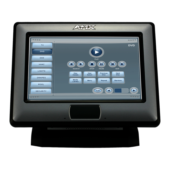
NXD-700i 7" Wall/Flush Mount Touch Panel with Intercom
NXT-CA7 7" Table Top Touch Panel
Touch Panels
L a s t R e v i s e d : 9 / 3 0 / 2 0 1 1

Advertisement

Table of Contents
loading
Need help?

Need help?

Do you have a question about the NXD-700i and is the answer not in the manual?

Questions and answers

Subscribe to Our Youtube Channel

Summary of Contents for AMX NXD-700i

  • Page 1 Operation/Reference Guide 7” Modero Touch Panels NXD-700i 7” Wall/Flush Mount Touch Panel with Intercom NXT-CA7 7” Table Top Touch Panel Touch Panels L a s t R e v i s e d : 9 / 3 0 / 2 0 1 1...
  • Page 2 AMX is not responsible for products returned without a valid RMA number. AMX is not liable for any damages caused by its products or for the failure of its products to perform. This includes any lost profits, lost savings, incidental damages, or consequential damages.
  • Page 3 LICENSE GRANT. AMX grants to Licensee the non-exclusive right to use the AMX Software in the manner described in this License. The AMX Software is licensed, not sold. This license does not grant Licensee the right to create derivative works of the AMX Software.
  • Page 5: Table Of Contents

    Step 1: Setup the Panel and PC for USB Communication ..........25 Step 2: Confirm the Installation of the USB Driver on the PC ........25 Step 3: Confirm and View Current AMX USB Device Connections........ 26 NXD-700i & NXT-CA7 7” Modero Touch Panels...
  • Page 6 Table of Contents Step 4: Configure a Virtual Master (using NetLinx Studio) for USB....... 27 Step 5: Confirm and View Current AMX USB Device Connections........ 29 Configuring a Wired Ethernet Connection.............. 30 Step 1: Configure the Panel’s Wired IP Settings............. 30 IP Settings section - Configuring a DHCP Address over Ethernet .........
  • Page 7 PAGE ............................75 PPOF ............................76 PPOG ............................76 PPON ............................76 Programming Numbers for Colors, Fonts, and Borders.......... 77 RGB Triplets and Names For Basic 88 Colors ............... 77 Font Styles and ID Numbers ..................78 NXD-700i & NXT-CA7 7” Modero Touch Panels...
  • Page 8 ^GDI ............................93 ^GIV ............................93 ^GLH ............................93 ^GLL ............................93 ^GRD ............................. 93 ^GRU ............................. 94 ^GSC ............................94 ^GSN ............................. 94 ^ICO ............................95 ^JSB ............................95 ^JSI ............................95 NXD-700i & NXT-CA7 7” Modero Touch Panels...
  • Page 9 @AKR ............................109 BEEP .............................109 BRIT ............................109 @BRT ............................109 DBEEP ..........................109 @EKP ............................109 PKEYP ...........................110 @PKP ............................110 SETUP ...........................110 SLEEP ...........................110 @SOU ...........................110 @TKP ............................ 111 TPAGEON ..........................111 TPAGEOFF ..........................111 @VKB ............................111 WAKE ...........................111 NXD-700i & NXT-CA7 7” Modero Touch Panels...
  • Page 10 ^ICM ............................ 118 ^ICS- ............................ 118 ^ICE' ............................ 119 ^ICM-TALK ........................... 119 ^ICM-LISTEN ........................119 ^ICM-MICLEVEL ........................119 ^ICM-MUTEMIC ........................119 ^ICM-SPEAKERLEVEL ......................119 Panel IR Commands ....................120 ^IRM ............................ 120 ^IRS ............................120 NXD-700i & NXT-CA7 7” Modero Touch Panels...
  • Page 11 Input Mask Operations....................133 Input Mask Literals ...................... 133 Input Mask Output Examples ..................134 URL Resources ...................... 134 Special Escape Sequences................... 135 Appendix B - Complex Script Support ............137 Overview ......................137 NXD-700i & NXT-CA7 7” Modero Touch Panels...
  • Page 12 Table of Contents viii NXD-700i & NXT-CA7 7” Modero Touch Panels...
  • Page 13: Modero 7" Touch Panels

    Modero 7" Touch Panels Modero 7" Touch Panels Overview The Modero® family of 7-inch Touch Panels includes the NXD-700i, and the NXT-CA7 (FIG. 1): NXD-700i (front view) (FG2258-10) NXT-CA7 (front view) (FG2258-09) FIG. 1 NXD-700i, and NXT-CA7 7-inch Modero Touch Panels Product specifications for each panel is provided on the following pages.
  • Page 14: Nxd-700I Overview

    Modero 7" Touch Panels NXD-700i Overview The NXD-700i (FG2258-10) is an incredibly versatile user interface, combining a sleek, compact size, Wall/ Flush Mount flexibility and the ability to create a high quality digital home/office intercom network or to make/receive digital local, long distance and international telephone calls.
  • Page 15 (10 Mbps or 100 Mbps), and whether to use half duplex or full duplex mode. • Power is supplied through Power Over Ethernet (PoE). • NXD-700i panels communicate with the NetLinx Master using the ICSP protocol over Ethernet. • LEDs show communication activity, connections, speeds, and mode...
  • Page 16: Nxd-700I Panel Connectors

    Modero 7" Touch Panels NXD-700i Panel Connectors FIG. 3 shows the connectors located on the NXD-700i: FIG. 3 Connector layout on the NXD-700i  The mini-USB port is used both for programming the touch panel and for audio output. ...
  • Page 17: Nxt-Ca7 Specifications

    PC and the target panel. The connector is also used for providing audio output for external speakers. Certifications: • FCC Part 15 Class B • CE • IEC60950 • RoHS NXD-700i & NXT-CA7 7” Modero Touch Panels...
  • Page 18: Nxt-Ca7 Panel Connectors

    The mini-USB port is used both for programming the touch panel and for audio output.  The mini-USB port automatically detects the presence of a headphone adaptor, allowing the port to be used for headphone connectivity.  The Ethernet connector also supports Power over Ethernet (POE) NXD-700i & NXT-CA7 7” Modero Touch Panels...
  • Page 19: Nxd-700I - Installation

    Installing the No-Button Trim Ring The NXD-700i panel is shipped from AMX with the default Button Trim Ring already installed. The unit is also shipped with a a No-Button Trim Ring that provides the option of changing the default configuration of the NXD Faceplate to that with no-button openings.
  • Page 20: Installing The Button Trim Ring

    Verify the No-Button Trim Ring is firmly inserted onto the Faceplate and that there are no gaps between this Trim Ring and the outer surface of the Faceplate. Place the Faceplate back onto the main NXD-700i unit. Make sure to align the Microphone, Light, and PIR Motion sensor locations on the main unit to their respective openings on the Faceplate assembly.
  • Page 21 Verify the Button Trim Ring is firmly inserted onto the Faceplate and that there are no gaps between this Trim Ring and the outer surface of the Faceplate. Place the Faceplate back onto the main NXD-700i unit. Make sure to align the Microphone, Light, and PIR Motion sensor locations on the main unit to their respective openings on the Faceplate assembly.
  • Page 22: Pre-Wall Installation Of The Conduit Box

    This section describes the installation procedures for the most common installation scenario. The most important thing to remember when mounting this conduit box is that the NXD-700i Mounting Tabs must lie flush against the outside of the sheetrock (FIG. 10).
  • Page 23: Installing The Nxd-700I Touch Panel

    Install the drywall/sheetrock before inserting the main NXD unit into the CB-TP7. Installing the NXD-700i Touch Panel The NXD-700i can be installed either directly into the (optional) CB-TP7 or other solid surface environment using the two different mounting options: drywall clips or solid surface screws.
  • Page 24: Installing The Panel Into Drywall Using Expansion Clips

    NXD-700i - Installation Carefully slide the main NXD-700i unit (B in FIG. 11) into the conduit box, so that all Mounting Tabs lie flush against the conduit box (C in FIG. 11). Insert and secure four #4-40 Mounting Screws (included) into their corresponding holes located along the sides of the NXD.
  • Page 25 Carefully insert the main unit (with expansion clips) into the cutout until the Mounting Tabs on the NXD unit lie flush against the wall. The drywall clip set must be re-ordered from AMX if the drywall clip is bent accidentally during an installation or removed during a re-installation.
  • Page 26: Installing The Panel Into A Flat Surface Using #4 Screws

    Cut out the surface for the NXD Wall Mount unit using the dimensions shown in FIG. 14. FIG. 14 NXD-700i Wall Mount panel dimensions using #4-40 mounting screws Remove the Faceplate/bezel (A in FIG. 15) from the main NXD unit (B in FIG. 15) by gripping the faceplate and pulling with gentle outward force.
  • Page 27: Installing The Panel Into An (Optional) Rack Mount Kit (Nxa-Rk7)

    Don’t disconnect the connectors from the touch panel. The unit must be installed with the necessary connectors before being inserted into the solid surface. Carefully slide the main unit into the cutout until the Mounting Tabs of the NXD-700i unit lie flush against the wall.
  • Page 28: Ethernet/Rj-45 Port: Connections And Wiring

    1 2 3 4 5 6 7 8 PoE power 8 --------- 8 Brown FIG. 17 diagrams the RJ-45 pinouts and signals for the Ethernet RJ-45 connector and cable. FIG. 17 RJ-45 wiring diagram NXD-700i & NXT-CA7 7” Modero Touch Panels...
  • Page 29: Nxt-Ca7 - Installation

    7 --------- 8 Brown-White 1 2 3 4 5 6 7 8 PoE power 8 --------- 8 Brown FIG. 19 diagrams the RJ-45 pinouts and signals for the Ethernet RJ-45 connector and cable. NXD-700i & NXT-CA7 7” Modero Touch Panels...
  • Page 30 NXT-CA7 - Installation FIG. 19 RJ-45 wiring diagram NXD-700i & NXT-CA7 7” Modero Touch Panels...
  • Page 31: Ps-Poe-Af Poe Injector

    • 90VAC Input • 0.6A max. Protection • Internal Primary Current Fuse • Inrush Limiting General Specifications Topology • Switching-Fixed • Frequency Flyback Dielectric Withstand • Primary-Secondary 3000VAC, 4250VDC • Secondary-Ground 500VDC Spacing 5mm Primary-Secondary NXD-700i & NXT-CA7 7” Modero Touch Panels...
  • Page 32: Environmental Specifications

    100,000 Calculated Hours Environmental Specifications Thermal Performance • Operating Temperature 0° C to 40° C • No Derating • Convectional Cooling • Non Vented Case Relative Humidity Non-Condensing 5% to 95% Altitude 0-10,000 feet NXD-700i & NXT-CA7 7” Modero Touch Panels...
  • Page 33: Panel Calibration

    When the panel is ready, the AMX Splash Screen is replaced by the Initial Panel Page. Calibrating the Panel Press and hold the grey Front Bezel button (FIG. 21) for 8 seconds to pass over the Setup page and access the Calibrate setup page (FIG.
  • Page 34 Calibrate button through a VNC window. This action causes the panel to go to the Calibrate page seen above, where the actual touch panel may be physically calibrated again using the above procedures. NXD-700i & NXT-CA7 7” Modero Touch Panels...
  • Page 35: Configuring Communication

    Static IP). Ethernet communication can only be achieved via a direct Ethernet connection. Before commencing, verify that you are using the latest NetLinx Master and Modero panel firmware, and also verify you are using the latest versions of AMX’s NetLinx Studio and TPDesign4 applications. These are available at www.amx.com.
  • Page 36 The mini-USB connector MUST be plugged into a panel that is already active before the PC can recognize the connection and assign an appropriate USB driver. NXD-700i & NXT-CA7 7” Modero Touch Panels...
  • Page 37: Configuring And Using Usb With A Virtual Master

    Step 2: Confirm the Installation of the USB Driver on the PC The first time each AMX touch panel is connected to the PC, it is detected as a new hardware device and the panel-specific USBLAN driver becomes associated with it.
  • Page 38: Step 3: Confirm And View Current Amx Usb Device Connections

    Confirm that a new USB detection icon (FIG. 26) appears in the lower-right taskbar on the PC display window. Double-click on the icon to open the Unplug or Eject Hardware window and confirm the AMX USB LAN LINK has been installed and is operating properly.
  • Page 39: Step 4: Configure A Virtual Master (Using Netlinx Studio) For Usb

    To remove the USB driver association from a previously connected touch panel, navigate back to the Device Manager, right-click on the panel’s USB driver (example AMX USB LAN LINK #2) and select Uninstall from the context menu and then OK.
  • Page 40 USB connection and Virtual Master setup procedures (outlined in this section). Refreshing the System sends out a request to the panel to respond and completes the communication (turning the System Connection icon green). NXD-700i & NXT-CA7 7” Modero Touch Panels...
  • Page 41: Step 5: Confirm And View Current Amx Usb Device Connections

    USB icon FIG. 30 USB icon Step 5: Confirm and View Current AMX USB Device Connections Use the CC-USB Type-A to Mini-B 5-wire programming cable (FG10-5965) to provide communication between the mini-USB Program port on the touch panel and the PC.
  • Page 42: Configuring A Wired Ethernet Connection

    Addressing/Network Addresses in the Tools > NetLinx Diagnostics dialog. Press the Back button to return to the Protected Setup page. Press the on-screen Reboot button to save any changes and restart the panel. NXD-700i & NXT-CA7 7” Modero Touch Panels...
  • Page 43: Ip Settings Section - Configuring A Static Ip Address Over Ethernet

    TCP when a reliable delivery is not required. This UDP enabling is done through a Telnet session on the Master. Refer to the installation manual for the particular NetLinx Master for more detailed information. NXD-700i & NXT-CA7 7” Modero Touch Panels...
  • Page 44: Step 3: Configure An Ethernet Connection Type

    Verify that the panel has been configured to communicate through an Ethernet cable connected from the panel to a valid Ethernet Hub. Launch NetLinx Studio (default location is Start > Programs > AMX Control Disc > NetLinx Studio). Select Settings > Master Communication Settings, from the Main menu to open the Master Communication Settings dialog (FIG.
  • Page 45 Click Done to accept the new value and return to the System Settings page. Do not alter the Master Port Number value. This is the default value used by NetLinx. Press the Back button to return to the Protected Setup page. NXD-700i & NXT-CA7 7” Modero Touch Panels...
  • Page 46: Master Connection Section - Netlinx Master Ethernet Ip Address - Url Mode

    Master, virtual or not. A Virtual Master system value can be set within the active AMX software applications such as NetLinx Studio, TPD4, or IREdit. If the panel does not appear within the OnLine Tree tab of the Workspace window of NetLinx Studio, check to make sure that the NetLinx Master System Number from within the Device Addressing dialog is correctly assigned.
  • Page 47: Master Connection Section - Netlinx Master Ethernet Ip Address - Auto Mode

    58 for more detailed information on G4 Web control. Verify that the NetLinx Master (ME260/64 or NI-Series) has been installed with the latest firmware KIT file from www.amx.com. Refer to the NetLinx Master instruction manual for more detailed information on the use of the new web-based NetLinx Security.
  • Page 48 Within the keypad, enter a unique numeric value to be assigned to the port being used by the VNC Web Server and press Done when finished. The default value is 5900. The remaining fields within the G4 Web Control Settings section of this page are read-only and cannot be altered. NXD-700i & NXT-CA7 7” Modero Touch Panels...
  • Page 49: Using The Netlinx Master To Control The G4 Panel

     If the Master has been previously configured for secured communication, click OK to accept the AMX SSL certificate (if SSL is enabled) and then enter a valid username and password into the fields within the Login dialog. Click OK to enter the information and proceed to the Master’s Manage WebControl Connections window.
  • Page 50 This is the IP address of the target touch panel, not the IP of the Master. The IP address may be found in the System Settings page (for more information, please refer to the System Settings Page section on page 55). If this field does not appear, continue to step 9. NXD-700i & NXT-CA7 7” Modero Touch Panels...
  • Page 51 G4 panel page and corresponds to the location of the mouse cursor. A left-mouse click on the computer-displayed panel page is the same as an actual touch on the target G4 panel page. NXD-700i & NXT-CA7 7” Modero Touch Panels...
  • Page 52 Configuring Communication NXD-700i & NXT-CA7 7” Modero Touch Panels...
  • Page 53: Upgrading Modero Firmware

    Type-A USB connector to the PC's USB port and restart your machine. After the NXD-700i/ NXT-CA7 panel powers-up, press and hold the grey Front Setup Access button for 4 seconds to continue with the setup process and proceed to the Setup page.
  • Page 54: Step 2: Prepare Netlinx Studio For Communication Via The Usb Port

    Step 2: Prepare NetLinx Studio for communication via the USB port Launch NetLinx Studio (default location is Start > Programs > AMX Control Disc > NetLinx Studio). Select Settings > Master Communication Settings from the Main menu to open the Master Communication Settings dialog (FIG.
  • Page 55: Step 3: Confirm And Upgrade The Firmware Via The Usb Port

    Shows NetLinx Studio version number Showing the current Modero panel firmware version and device number FIG. 42 NetLinx Workspace window (showing the panel connection via a Virtual NetLinx Master) NXD-700i & NXT-CA7 7” Modero Touch Panels...
  • Page 56 If the panel firmware being used is not current, download the latest Kit file by first logging in to www.amx.com and then navigate to Tech Center > Firmware Files and from within the Modero section of the web page locate your Modero panel.
  • Page 57: Setup Pages And Descriptions

    The Setup page (FIG. 45) centers around basic Modero panel properties, such as the Connection Status of the panel, Display Timeout, Inactivity Page Flip Time, Inactivity page file, and the Panel Brightness. FIG. 45 Setup page NXD-700i & NXT-CA7 7” Modero Touch Panels...
  • Page 58 • The Auto Brightness button, when selected, will cause the panel to dim as the light level decreases, in order to reflect the brightness level of the room. If the panel is touched, the backlight will temporarily brighten the panel more than the previously selected level. NXD-700i & NXT-CA7 7” Modero Touch Panels...
  • Page 59: Information

    Displays the dealer ID number (unique to every dealer and entered in TPD4). Job Name: Displays the job name. Sales Order: Displays the sales order information. Purchase Order: Displays the purchase order information. NXD-700i & NXT-CA7 7” Modero Touch Panels...
  • Page 60: Panel Information Page

    Project Information Page (Cont.) AMX IR Port: Displays the AMX 38 kHz IR channel port used by the IR receiver on the panel. • This information is pulled by the panel from AMX IR Receivers section of the TPD4 Project Properties > IR Emitters & Receivers tab.
  • Page 61: Time & Date Settings Page

    NetLinx Master. If either the Time or Date is modified on this page and then updated to the Master by pressing the Set Time button, all devices communicating to that target Master will then be updated to reflect the new information. FIG. 49 Time and Date Settings page NXD-700i & NXT-CA7 7” Modero Touch Panels...
  • Page 62 • Select the Second field and use the UP/DN buttons to alter the second value (range = 0 - 59). NXD-500i touch panels do not have an onboard clock. This page both receives and sets the time and date of the NetLinx Master. NXD-700i & NXT-CA7 7” Modero Touch Panels...
  • Page 63: Audio Settings Page

    The following is a listing of supported sampling rates associated for WAV files played on a NXD-500i panel. Some WAV files currently played on other Modero panels may not work on a NXD-500i. The supported sampling rates for WAV files are: NXD-700i & NXT-CA7 7” Modero Touch Panels...
  • Page 64: Protected Setup Navigation Buttons

    NetLinx Master. Enter the factory default password (1988) into the password keypad to access this page. FIG. 52 Protected Setup page-showing default values The elements of the Protected Setup page are described in the table below: NXD-700i & NXT-CA7 7” Modero Touch Panels...
  • Page 65 • The Remove User Pages button allows the removal of all current TPD4 touch panel pages currently on the panel (including the pre-installed AMX Demo pages). - Pressing this button launches a Confirmation dialog (FIG. 53) which asks to confirm your selection.
  • Page 66: Security Settings

    • Login failure attempt pauses 4 seconds before another login attempt is allowed. • After 3 consecutive unsuccessful SSH login attempts, login lockout is enabled for 15 minutes. • Login and logout audit logging is enabled. NXD-700i & NXT-CA7 7” Modero Touch Panels...
  • Page 67: System Settings Page

    For more information on configuring AMX devices for a secure environment, please refer to the guide Security Profiles: Configuring AMX Devices For Installation Into a Secure Environment, available at www.amx.com.
  • Page 68 • Choices are: Auto, 10 Half Duplex, 10 Full Duplex, 100 Half Duplex, or 100 Full Duplex. MAC Address: Displays a read-only field that is factory set by AMX for the built-in Ethernet interface. Master Connection: Sets the NetLinx Master communication values:...
  • Page 69: Calibrate Page

    G4 Web Control. Navigate to the Protected Setup page and press the Calibrate button through the VNC window. This action causes the panel to go to the Calibrate page seen above, where the touch panel may be physically re-calibrated again using the above procedures. NXD-700i & NXT-CA7 7” Modero Touch Panels...
  • Page 70: G4 Web Control Settings Page

    • This Web Control tab displays a G4 icon alongside the link to the Web Control Name given to this panel (FIG. 58). Web Control Password: Allows entry of the G4 Authentication session password associated for VNC web access of this panel. NXD-700i & NXT-CA7 7” Modero Touch Panels...
  • Page 71: Other Settings

    Holding down the Other Settings button provides a menu to select the Image Caching page, the Password Settings page, the Sensor Settings page, or the SIP Settings page (FIG. 59). Select either option to access that page. FIG. 59 Other Settings popup menu NXD-700i & NXT-CA7 7” Modero Touch Panels...
  • Page 72: Cache Settings Page

    Allocates Flash memory for image caching. Flash Cache Size Press the Up and Down arrows to add and remove flash memory. Flash memory allocation cannot exceed the amount of Flash memory on the panel. NXD-700i & NXT-CA7 7” Modero Touch Panels...
  • Page 73: Setting The Image Cache

    Press the Cache button in the Other Settings popup menu. This opens the Cache Settings page. Press Clear Cache. This clears all image cache currently stored on the panel (both Flash and RAM). NXD-700i & NXT-CA7 7” Modero Touch Panels...
  • Page 74: Checking Image Cache Status

    • The PASSWORD 1, 2, 3, 4 and 5 (protected) buttons open a keyboard to enter alphanumeric values associated to the selected password group. Note: Clearing Password #5 removes the need to enter a password before accessing the Protected Setup page. NXD-700i & NXT-CA7 7” Modero Touch Panels...
  • Page 75: Sensor Settings

    NetLinx Master (set in TPD4) (read-only). • The Motion Sensor Channel field indicates the channel used to report the motion sensor channel back to the NetLinx Master (set in TPD4) (read-only). NXD-700i & NXT-CA7 7” Modero Touch Panels...
  • Page 76: Making The Most Of The Light Bargraph

    IP phone. With a CSG SIP Communications Gateway (FG2182-01, -02, -03), you can use your touch panel to make and receive local, long distance, and international phone calls, and have access to phone features like call waiting, caller ID, call forwarding, call queuing, and voice mail. NXD-700i & NXT-CA7 7” Modero Touch Panels...
  • Page 77 This option enables the SIP Stack on startup. If you disable this option, the panel will not attempt to read the rest of the configuration and will not register with a proxy server. However, point-to-point SIP will still be enabled allowing for existing intercom functionality. NXD-700i & NXT-CA7 7” Modero Touch Panels...
  • Page 78: Tools

    The options on the Panel Connection Logs page allows viewing and tracking of the connection history for the panel (FIG. 65). Features on this page are as follows: Checking the Panel Connection Logs From the Protected Setup page, press the Tools button. This opens the Tools menu. NXD-700i & NXT-CA7 7” Modero Touch Panels...
  • Page 79: Refreshing The Panel Connections Log

    From the Protected Setup page, press the Tools button. This opens the Tools menu. Within the Tools menu, press the Panel Logs button. Push the Clear button and confirm your selection. Panel Statistics Page NXD-700i & NXT-CA7 7” Modero Touch Panels...
  • Page 80 The master sends this message once every 5 seconds to all connected devices. Total • Received - The total Blink messages received by the panel. • Missed - The total Blink messages missed by the panel. NXD-700i & NXT-CA7 7” Modero Touch Panels...
  • Page 81: Checking The Panel Statistics

    Closes the Connection Utility popup. Wired icon: The icon to the left of the Connection Status Icon displays that the current connection to the Master is Wired (image of three networked computers). Connection Utility Window (Cont.) NXD-700i & NXT-CA7 7” Modero Touch Panels...
  • Page 82: Using The Connection Utility

    Within the Tools menu, press the Connection Utility button to launch the Connection Utility popup. The Connection Information notes the IP of the connected master and the IP of the panel. The Connection Statistics show the current quality of the panel connection. Push Close when finished. NXD-700i & NXT-CA7 7” Modero Touch Panels...
  • Page 83: Programming

    Clear all popup pages from specified popup group. Syntax: "'@CPG-<popup group name>'" Variable: popup group name = 1 - 50 ASCII characters. Name of the popup group. Example: SEND_COMMAND Panel,"'@CPG-Group1'" Clears all popup pages from the popup group ’Group1’. NXD-700i & NXT-CA7 7” Modero Touch Panels...
  • Page 84: Dpg

    = 1 - 50 ASCII characters. Name of the page the popup is displayed hide effect time = Given in 1/10ths of a second. Example: SEND_COMMAND Panel,"'@PHT-Popup1;50'" Sets the Popup1 hide effect time to 5 seconds. NXD-700i & NXT-CA7 7” Modero Touch Panels...
  • Page 85: Ppa

    This command works in the same way as the 'Clear Group' command in TPDesign 4. Syntax: "'@PPK-<popup page name>'" Variable: popup page name = 1 - 50 ASCII characters. Name of the popup page. Example: SEND_COMMAND Panel,"'@PPK-Popup1'" Kills the popup page ’Popup1’ on all pages. NXD-700i & NXT-CA7 7” Modero Touch Panels...
  • Page 86: Ppm

    Sets the popup page ’Popup1’ to timeout within 3 seconds. @PPX Close all popups on all pages. This command works in the same way as the 'Clear All' command in TPDesign4. Syntax: "'@PPX'" Example: SEND_COMMAND Panel,"'@PPX'" Close all popups on all pages. NXD-700i & NXT-CA7 7” Modero Touch Panels...
  • Page 87: Pse

    Flips to a page with a specified page name. If the page is currently active, it will not redraw the page. Syntax: "'PAGE-<page name>'" Variable: page name = 1 - 50 ASCII characters. Name of the page the popup is displayed On. Example: SEND_COMMAND Panel,"'PAGE-Page1'" Flips to page1. NXD-700i & NXT-CA7 7” Modero Touch Panels...
  • Page 88: Ppof

    = 1 - 50 ASCII characters. Name of the page the popup is displayed On. Example: SEND_COMMAND Panel,"'PPON-Popup1; Main'" Activates the popup page ’Popup1’ on the Main page. Example 2: SEND_COMMAND Panel,"'PPON-Popup1'" Activates the popup page ’Popup1’ on the current page. NXD-700i & NXT-CA7 7” Modero Touch Panels...
  • Page 89: Programming Numbers For Colors, Fonts, And Borders

    Very Light Cyan Black Light Cyan TRANSPARENT Cyan Medium Cyan Dark Cyan Very Dark Cyan Very Light Aqua Light Aqua Aqua Medium Aqua Dark Aqua Very Dark Aqua Very Light Blue Light Blue NXD-700i & NXT-CA7 7” Modero Touch Panels...
  • Page 90: Font Styles And Id Numbers

    Border styles No border 10-11 Picture frame Single line Double line Double line Bevel-S Quad line Bevel-M Circle 15 22-23 Circle 15 Single line 24-27 Neon inactive-S Double line 40-41 Diamond 55 Quad line NXD-700i & NXT-CA7 7” Modero Touch Panels...
  • Page 91: Tpd4 Border Styles By Name

    Menu Top Rounded 185 Oval V 75x150 Menu Top Rounded 195 Oval V 100x200 Menu Right Rounded 15 Picture Frame Menu Right Rounded 25 Quad Line Menu Right Rounded 35 Single Line Menu Right Rounded 45 NXD-700i & NXT-CA7 7” Modero Touch Panels...
  • Page 92: Telnet Commands

    • Light - threshold: The light threshold set by the user. When "BL lvl" falls below the threshold the channel is activated with a "push" or "on". Above threshold is "release" or "off". NXD-700i & NXT-CA7 7” Modero Touch Panels...
  • Page 93: Cal Light

    ClearA[ll] - Clear all popup pages from all pages page name = 1 - 50 ASCII characters. Example: SEND COMMAND Panel,"'^APF-400,Stan,Main Page'" Assigns a button to a standard page flip with page name 'Main Page'. NXD-700i & NXT-CA7 7” Modero Touch Panels...
  • Page 94: Bat

    1 = Off state and 2 = On state). color value = Refer to theRGB Values for all 88 Basic Colors table on page 77 for more information. Example: SEND_COMMAND Panel,"'^BCB-500.504&510,1,12'" Sets the Off state border color to 12 (Yellow). NXD-700i & NXT-CA7 7” Modero Touch Panels...
  • Page 95: Bcf

    1 = Off state and 2 = On state). color value = Refer to theRGB Values for all 88 Basic Colors table on page 77 for more information. Example: SEND_COMMAND Panel,"'^BCT-500.504&510,1,12'" Sets the Off state border color to 12 (Yellow). NXD-700i & NXT-CA7 7” Modero Touch Panels...
  • Page 96: Bdo

    = Refer to theText Area Input Masking section on page 132 for character types. Example: SEND_COMMAND Panel,"'^BIM-500,AAAAAAAAAA'" Sets the input mask to ten ’A’ characters, that are required, to either a letter or digit (entry is required). NXD-700i & NXT-CA7 7” Modero Touch Panels...
  • Page 97: Bmc

    Copies the OFF state border, font, Text, bitmap, icon, fill color and text color of the button with a variable text address of 315 onto the OFF state border, font, Text, bitmap, icon, fill color and text color of the button with a variable text address of 150. NXD-700i & NXT-CA7 7” Modero Touch Panels...
  • Page 98: Bmf

    ’%GH<bargraph hi>’ = Set the bargraph upper limit. ’%GL<bargraph low>’ = Set the bargraph lower limit. ’%GN<bargraph slider name>’ = Set the bargraph slider name/Joystick cursor name. ’%GC<bargraph slider color>’ = Set the bargraph slider color/Joystick cursor color. NXD-700i & NXT-CA7 7” Modero Touch Panels...
  • Page 99: Bmi

    "'^BML-<vt addr range>,<max length>'" Variable: variable text address range = 1 - 4000. max length = 2000 (0=no max length). Example: SEND_COMMAND Panel,"'^BML-500,20'" Sets the maximum length of the text area input button to 20 characters. NXD-700i & NXT-CA7 7” Modero Touch Panels...
  • Page 100: Bmp

    Set the TakeNote network port for the specified Addresses. Syntax: "'^BNT-<vt addr range>,<network port>'" Variable: variable text address range = 1 - 4000. network port = 1 - 65535. Example: SEND_COMMAND Panel,"'^BNT-973,5000'" Sets the TakeNote button network port to 5000. NXD-700i & NXT-CA7 7” Modero Touch Panels...
  • Page 101: Bop

    Sets the border by number (#10) to those buttons with the variable text range of 500-504 & 510-515. SEND_COMMAND Panel,"'^BOR-500.504&510,AMX Elite -M'" Sets the border by name (AMX Elite) to those buttons with the variable text range of 500-504 & 510-515. Note: The border style is available through the TPDesign4 border-style drop-down list.
  • Page 102: Brd

    1 = Off state and 2 = On state). sound name = (blank - sound cleared, not matched - button sound not changed). Example: SEND_COMMAND Panel,"'^BSO-500,1&2,music.wav'" Assigns the sound 'music.wav' to the button Off/On states. NXD-700i & NXT-CA7 7” Modero Touch Panels...
  • Page 103: Bvl

    = 1 - 256 for multi-state buttons (0 = All states, for General buttons 1 = Off state and 2 = On state). word wrap = (0=Off and 1=On). Default is Off. Example: SEND_COMMAND Panel,"'^BWW-500,1,1'" Sets the word wrap on for the button’s Off state. NXD-700i & NXT-CA7 7” Modero Touch Panels...
  • Page 104: Cpf

    = Range = 1 - XXX. Refer to theDefault Font Styles and ID Numbers table on page 78. Example: SEND_COMMAND Panel,"'^FON-500.504&510.515,1&2,4'" Sets the font size to font ID #4 for the On and Off states of buttons with the variable text range of 500-504 & 510-515. NXD-700i & NXT-CA7 7” Modero Touch Panels...
  • Page 105: Gdi

    "'^GRD-<vt addr range>,<bargraph ramp down time>'" Variable: variable text address range = 1 - 4000. bargraph ramp down time = In 1/10th of a second intervals. Example: SEND_COMMAND Panel,"'^GRD-500,200'" Changes the bargraph ramp down time to 20 seconds. NXD-700i & NXT-CA7 7” Modero Touch Panels...
  • Page 106: Gru

    Windows Windows Active Joystick Cursor Names: None Arrow Ball Circle Crosshairs Gunsight Hand Metal Spiral Target View Finder Example: SEND_COMMAND Panel,"'^GSN-500,Ball'" Changes the bargraph slider name or the Joystick cursor name to ’Ball’. NXD-700i & NXT-CA7 7” Modero Touch Panels...
  • Page 107: Ico

    = Value of 1 - 9 corresponds to the following locations: Zero can be used for an absolute position Example: SEND_COMMAND Panel,"'^JSI-500.504&510.515,1&2,1'" Sets the Off/On state icon alignment to upper left corner for those buttons with variable text range of 500-504 & 510-515. NXD-700i & NXT-CA7 7” Modero Touch Panels...
  • Page 108: Jst

    "'^SHO-<vt addr range>,<command value>'" Variable: variable text address range = 1 - 4000. command value = (0= hide, 1= show). Example: SEND_COMMAND Panel,"'^SHO-500.504&510.515,0'" Hides buttons with variable text address range 500-504 & 510-515. NXD-700i & NXT-CA7 7” Modero Touch Panels...
  • Page 109: Tec

    1 = Off state and 2 = On state). new text = 1 - 50 ASCII characters. Example: SEND_COMMAND Panel,"'^TXT-500.504&510.515,1&2,Test Only'" Sets the On and Off state text for buttons with the variable text ranges of 500-504 & 510-515. NXD-700i & NXT-CA7 7” Modero Touch Panels...
  • Page 110: Text Effect Names

    • Medium Drop Shadow 6 with outline • Soft Drop Shadow 7 with outline • Medium Drop Shadow 7 with outline • Soft Drop Shadow 8 with outline • Medium Drop Shadow 8 with outline NXD-700i & NXT-CA7 7” Modero Touch Panels...
  • Page 111: Button Query Commands

    (this is not encoded size) slong value3 index of first character (usually 1 or same as optional index string text the text from the button text length (string encode) button text length NXD-700i & NXT-CA7 7” Modero Touch Panels...
  • Page 112: Bcb

    Gets the button 'OFF state' fill color information. The result sent to the Master would be: ButtonGet Id = 529 Type = 1012 Flag VALUE1 = 1 VALUE2 = 9 VALUE3 = 0 TEXT = #FF8000FF TEXT LENGTH = 9 NXD-700i & NXT-CA7 7” Modero Touch Panels...
  • Page 113: Bct

    Gets the button 'OFF state' bitmap information. The result sent to the Master would be: ButtonGet Id = 529 Type = 1002 Flag VALUE1 = 1 VALUE2 = 9 VALUE3 = 0 TEXT = Buggs.png TEXT LENGTH = 9 NXD-700i & NXT-CA7 7” Modero Touch Panels...
  • Page 114: Bop

    The result sent to the Master would be: ButtonGet Id = 529 Type = 1014 Flag VALUE1 = 1 VALUE2 = 22 VALUE3 = 0 TEXT = Double Bevel Raised -L TEXT LENGTH = 22 NXD-700i & NXT-CA7 7” Modero Touch Panels...
  • Page 115: Bww

    Gets the button 'OFF state' font type index information. The result sent to the Master would be: ButtonGet Id = 529 Type = 1007 Flag VALUE1 = 1 VALUE2 = 72 VALUE3 = 0 TEXT TEXT LENGTH = 0 NXD-700i & NXT-CA7 7” Modero Touch Panels...
  • Page 116: Ico

    Gets the button 'OFF state' bitmap justification information. The result sent to the Master would be: ButtonGet Id = 529 Type = 1005 Flag VALUE1 = 1 VALUE2 = 5 VALUE3 = 0 TEXT TEXT LENGTH = 0 NXD-700i & NXT-CA7 7” Modero Touch Panels...
  • Page 117: Jsi

    Gets the button 'OFF state' text justification information. The result sent to the Master would be: ButtonGet Id = 529 Type = 1004 Flag VALUE1 = 1 VALUE2 = 1 VALUE3 = 0 TEXT TEXT LENGTH = 0 NXD-700i & NXT-CA7 7” Modero Touch Panels...
  • Page 118: Tec

    The result sent to the Master would be: ButtonGet Id = 529 Type = 1008 Flag VALUE1 = 1 VALUE2 = 18 VALUE3 = 0 TEXT = Hard Drop Shadow 3 TEXT LENGTH = 18 NXD-700i & NXT-CA7 7” Modero Touch Panels...
  • Page 119: Panel Runtime Operations

    Outputs a beep of duration 1 beep even if beep is Off. ADBEEP Output a double beep even if beep is Off. Syntax: "'ADBEEP'" Example: SEND COMMAND Panel,"'ADBEEP'" Outputs a double beep even if beep is Off. NXD-700i & NXT-CA7 7” Modero Touch Panels...
  • Page 120: Akb

    = 1 - 50 ASCII characters. prompt text = 1 - 50 ASCII characters. Example: SEND COMMAND Panel,"'@AKP-12345678;ENTER PASSWORD'" Pops up the Keypad and initializes the text string '12345678' with prompt text ’ENTER PASSWORD’. NXD-700i & NXT-CA7 7” Modero Touch Panels...
  • Page 121: Akr

    = 1 - 50 ASCII characters. prompt text = 1 - 50 ASCII characters. Example: SEND COMMAND Panel,"'@EKP-33333333;Enter Password'" Pops up the Keypad and initializes the text string '33333333' with prompt text 'Enter Password'. NXD-700i & NXT-CA7 7” Modero Touch Panels...
  • Page 122: Pkeyp

    @SOU Play a sound file. Syntax: "'@SOU-<sound name>'" Variables: sound name = Name of the sound file. Supported sound file formats are: WAV & MP3. Example: SEND COMMAND Panel,"'@SOU-Music.wav'" Plays the 'Music.wav' file. NXD-700i & NXT-CA7 7” Modero Touch Panels...
  • Page 123: Tkp

    "'@VKB'" Example: SEND COMMAND Panel,"'@VKB'" Pops-up the virtual keyboard. WAKE Force the panel out of screen saver mode. Syntax: "'WAKE'" Example: SEND COMMAND Panel,"'WAKE'" Forces the panel out of the screen saver mode. NXD-700i & NXT-CA7 7” Modero Touch Panels...
  • Page 124: Input Commands

    ASCII character set. Syntax: "'^VKS-<string>'" Variable: string = Only 1 string per command/only one stroke per command. Example: SEND COMMAND Panel,"'^VKS-'8" Sends out the keystroke 'backspace' to the G4 application. NXD-700i & NXT-CA7 7” Modero Touch Panels...
  • Page 125: Embedded Codes

    Print Screen ($9B) SYSRQ ($9C) ($9D) Windows ($9E) Menu ($9F) Up Arrow ($A0) Down Arrow ($A1) Left Arrow ($A2) Right Arrow ($C0) CTRL key up ($C1) ALT key up ($C2) Shift key up NXD-700i & NXT-CA7 7” Modero Touch Panels...
  • Page 126: Panel Setup Commands

    Sets the page flip password on Password Level 1 to 'Main'. @RPP Reset the protected password. @RPP resets the protected password to its default (1988). Syntax: "'@RPP'" Example: SEND COMMAND Panel,"'@RPP'" Resets the protected Setup page password to ‘1988’. NXD-700i & NXT-CA7 7” Modero Touch Panels...
  • Page 127: Dynamic Image Commands

    Note that the %%5F in the file path is actually encoded as %5F. ^RFR Force a refresh for a given resource. Syntax: "'^RFR-<resource name>'" Variable: resource name = 1 - 50 ASCII characters. Example: SEND_COMMAND Panel,"'^RFR-Sports_Image'" Forces a refresh on ’Sports_Image’. NXD-700i & NXT-CA7 7” Modero Touch Panels...
  • Page 128: Raf, ^Rmf - Embedded Codes

    Set Directory path. The path must be a valid HTTP URL minus the ’%A <path>’ protocol, host and filename. The only exception to this is the inclusion of special escape sequences and in the case of FTP protocol, regular expressions. NXD-700i & NXT-CA7 7” Modero Touch Panels...
  • Page 129: Escape Sequences

    Current state Address code Address port Channel code Channel port Level code Level port X Resolution of Current button Y Resolution of Current button Name of Button For instance, http://www.amx.com/img.asp?device=$DV would become http://www.amx.com/img.asp?device=10001. NXD-700i & NXT-CA7 7” Modero Touch Panels...
  • Page 130: Intercom Commands

    SEND_COMMAND TP2, "^ICS-239.252.1.1,9002,9000,0" SEND_COMMAND TP3, "^ICS-239.252.1.1,9002,9000,0" Example of setting up a baby monitor call where the first panel is listening to the microphone audio coming from the second panel: SEND_COMMAND TP1, "^ICS-192.168.0.3,9000,9002,0" SEND_COMMAND TP2, "^ICS-192.168.0.4,9002,9000,1" NXD-700i & NXT-CA7 7” Modero Touch Panels...
  • Page 131: Ice

    SEND_COMMAND <DEV>, "^ICM-MUTEMIC" Variables: None. Example: SEND_COMMAND TP1, "^ICM-MUTEMIC,1" ^ICM-SPEAKERLEVEL Set the speaker level during an intercom call. Syntax: SEND_COMMAND <DEV>, "^ICM-SPEAKERLEVEL,55" Variables: Valid levels are from 0 to 100. Example: SEND_COMMAND TP1, "^ICM-SPEAKERLEVEL,55" NXD-700i & NXT-CA7 7” Modero Touch Panels...
  • Page 132: Panel Ir Commands

    The ^IRS command is needed to enable the received AMX 38K or 455k. In some cases, both of these ports cannot be enabled at the same time.
  • Page 133: Sip Commands

    = The name associated with the caller number. connection id = The identifying number of the connection. timestamp = The current time in MM/DD/YY HH:MM:SS format. Example: SEND_COMMAND Panel,"'^PHN-INCOMING, 2125551000, AMX, 07/22/08 12:00:00, 1'" NXD-700i & NXT-CA7 7” Modero Touch Panels...
  • Page 134: Phn-Linestate

    Indicates the panel is redialing the number. Syntax: "'^PHN-REDIAL, <number>'" Variable: number = The phone number to dial. Example: SEND_COMMAND Panel,"'^PHN-REDIAL, 2125551000’" ^PHN-TRANSFERRED Indicates a call has been transferred. Syntax: "'^PHN-TRANSFERRED'" Example: SEND_COMMAND Panel,"'^PHN-TRANSFERRED’" NXD-700i & NXT-CA7 7” Modero Touch Panels...
  • Page 135: Phn-Answer

    = The identifying number of the connection Example: SEND_COMMAND Panel,"'^PHN-HANGUP, 1'" ^PHN-HOLD Places the call on hold. Syntax: "’^PHN-HOLD, <connection id>’" Variable: connection id = The identifying number of the connection Example: SEND_COMMAND Panel,"'^PHN-HOLD, 1'" NXD-700i & NXT-CA7 7” Modero Touch Panels...
  • Page 136: Phn-Setup-Domain

    = The realm used for authentication Example: SEND_COMMAND Panel,"’^PHN-SETUP-DOMAIN,asterisk’" ^PHN-SETUP-ENABLE Registers a new user Once the configuration has been updated, the ENABLE command should be run to re-register the new user. Syntax: "’^PHN-SETUP-ENABLE’" NXD-700i & NXT-CA7 7” Modero Touch Panels...
  • Page 137: Phn-Setup-Password

    IP = The IP address for the STUN server Example: SEND_COMMAND Panel,"’^PHN-SETUP- STUNADDR,192.168.223.111’" ^PHN-SETUP-USERNAME Sets the user name for authentication with the proxy server. Syntax: "’^PHN-SETUP-USERNAME,<username>’" Variable: username = The user name (usually the phone extension) Example: SEND_COMMAND Panel,"’^PHN-SETUP-USERNAME,6003’" NXD-700i & NXT-CA7 7” Modero Touch Panels...
  • Page 138 Programming NXD-700i & NXT-CA7 7” Modero Touch Panels...
  • Page 139: Troubleshooting

    System Tray. • Double click on the icon to bring up the list of USB devices (you should see the "AMX USB LAN LINK" device in the list). • If the "Install Driver" dialog doesn't appear automatically, select the "Properties"...
  • Page 140 PC, either within the NetLinx Studio or necting. TPDesign4 applications. • Remove the USB connector from the panel and close any AMX applications. • Reboot the panel. • Launch the AMX application and attempt reconnect to the panel.
  • Page 141 "Mid Range Fallout" problem. • This is due to the graphics controller settings in the firmware. • Update to the latest v2.XX.XX firmware. Visit the www.amx.com > Tech Center > Downloadable Files > Firmware Files > Modero panels, and then download the KIT file to your computer.
  • Page 142 "graphics hierarchy" errors, etc.… indicating problems with the Flash memory. • Panel will not boot, or gets stuck on "AMX" splash screen. • Other problems also started after downloading to a new panel or a panel with a TPD4 file that takes up a considerable amount of the available Flash memory.
  • Page 143: Appendix A - Text Formatting Codes

    Example Format Display $A out of $R 32 out of 100 $A of 0 - $R 32 of 0 - 100 $V of $L - $H 532 of 500 - 600 NXD-700i & NXT-CA7 7” Modero Touch Panels...
  • Page 144: Text Area Input Masking

    - Sets the input mask for the specified addresses. (see the ^BIM section on page 84). • ^BMF subcommand - sets the input mask of a text area (see the ^BMF section on page 86). NXD-700i & NXT-CA7 7” Modero Touch Panels...
  • Page 145: Input Mask Ranges

    Example 1: If typing "125" into a field accepting 0-100, then the values displayed will be "1", "12", "25".  Example 2: If the max for the field was 20, then the values displayed will be "1", "12", "5". NXD-700i & NXT-CA7 7” Modero Touch Panels...
  • Page 146: Input Mask Output Examples

    (HyperText Transport Protocol) and that the information resides on a host machine named www.amx.com. The image on that host machine is given an assignment name by the program of company-info-home.asp (Active Server Page).
  • Page 147: Special Escape Sequences

    Y Resolution of current panel mode/file X Resolution of current button Y Resolution of current button Name of button Current state Address Code Address Port Channel Code Channel Port Level Code Level Port NXD-700i & NXT-CA7 7” Modero Touch Panels...
  • Page 148 Appendix A - Text Formatting Codes NXD-700i & NXT-CA7 7” Modero Touch Panels...
  • Page 149: Appendix B - Complex Script Support

    In some cases, the user may need correct rendering of mixed left-to-right and right-to-left text, and may display both of these together in the same page (FIG. 69). Text edit boxes only operate left-to-right. FIG. 69 Mixed left-to-right and right-to-left text NXD-700i & NXT-CA7 7” Modero Touch Panels...
  • Page 150 Text in these languages can still be pasted via the clipboard or via the Alt-<Scan Code> method. For more information on TPDesign4 and its complex script support, please refer to the TPDesign4 (v3.0 or higher) Operation Reference Guide, available at www.amx.com. NXD-700i & NXT-CA7 7” Modero Touch Panels...
  • Page 151 Appendix B - Complex Script Support NXD-700i & NXT-CA7 7” Modero Touch Panels...
  • Page 152 It’s Your World - Take Control™ 3000 RESEARCH DRIVE, RICHARDSON, TX 75082 USA • 800.222.0193 • 469.624.8000 • 469-624-7153 fax • 800.932.6993 technical support • www.amx.com...

This manual is also suitable for:

Nxt-ca7

Table of Contents