AMX NXD-CV5 Operation/Reference Manual
5” modero g4 widescreen video touch panels
Hide thumbs
Also See for NXD-CV5:
- Operation/reference manual (274 pages) ,
- Specifications (2 pages) ,
- Installation manual (2 pages)
Table of Contents
Advertisement
Quick Links
Download this manual
See also:
Installation Manual
Advertisement
Table of Contents

Related Manuals for AMX NXD-CV5


Summary of Contents for AMX NXD-CV5
- Page 1 Operation/Reference Guide Modero ® G4 Touch Panel NXD-CV5 5” Modero Widescreen Video Touch Panels L as t R e vi s ed: 1 0 /1 /20 0 8 To u ch P a n e l s...
- Page 2 RMA number. AMX is not liable for any damages caused by its products or for the failure of its products to perform. This includes any lost profits, lost savings, incidental damages, or consequential damages. AMX is not liable for any claim made by a third party or by an AMX Dealer for a third party.
-
Page 3: Table Of Contents
Step 1: Setup the Panel and PC for USB Communication ... 35 Step 2: Confirm the Installation of the USB Driver on the PC ... 35 Step 3: Confirm and View the current AMX USB device connections ... 37 5" Modero Widescreen Touch Panel... - Page 4 Table of Contents Step 4: Use the USB to Configure a Virtual Master (using NetLinx Studio) ... 38 Step 5: Confirm and View the current AMX USB device connections ... 40 Configuring a Wired Ethernet Connection... 40 Step 1: Configure the Panel’s Wired IP Settings... 41 IP Settings section - Configuring a DHCP Address over Ethernet ...
- Page 5 Sensor Setup ... 78 Making the most of the Automated Brightness Control feature (DIM Mode) ... 80 Other Settings ... 81 Image Caching Page... 82 Setting the image cache... 83 Clearing the image cache ... 84 Checking image cache status ... 84 Password Settings Page ...
- Page 6 Table of Contents Input mask character types ... 148 Input mask ranges ... 149 Input mask next field characters... 149 Input mask operations... 149 Input mask literals ... 149 Input mask output examples ... 150 URL Resources ... 151 Special escape sequences ... 151 5"...
-
Page 7: Introduction
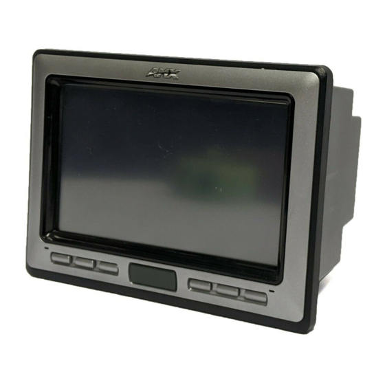
Introduction The NXD-CV5 5" Modero Widescreen Color Video Touch Panels (FIG. 1) are the industry’s first widescreen mini-touch panels and are available only through AMX. FIG. 1 Sample 5" Video Touch Panel This is the first 5" diagonal Widescreen Color Active video-capable touch panel in the control and automation industry. -
Page 8: Cv5 Specifications
(3 RU - rack units high) 5.22" x 19.0" x 0.50" (13.26 cm x 48.26 cm x 1.27 cm) • NXD-CV5 (with faceplate): 4.15" x 5.59" x 3.23" (10.50 cm x 14.20 cm x 8.20 cm) • CB-TP5 Rough-In/Wallbox (optional): 4.27" x 5.14" x 3.40"... - Page 9 • The IR receiver is located beneath the translucent Front Setup button. When an IR code is detected it is sent to the NetLinx Master as a push on the appropriate AMX IR channel. • IR receivers and transmitters on G4 panels share the device address number of the panel.
- Page 10 • Storage Temperature: -20° C (-4° F) to 60° C (140° F) • Storage Humidity: 5% - 85% RH • Installation Kit for NXD-CV5 panels (KA2261-01): - 2-pin 3.5 mm mini-Phoenix connector - Three Drywall clips (62-5924-05) and #6 - sheet metal screws - Three Phillips-head screws (#4-40 x 0.250 Black)
-
Page 11: Cv5 Panels - Connector Layout
CV5 Panels - Connector Layout FIG. 3 shows the layout of the connectors (located on the left side panel of the NXD-CV5 panel). Ethernet (CAT5) Power FIG. - Page 12 Introduction 5" Modero Widescreen Touch Panel...
-
Page 13: Cv5 Touch Panel Accessories
CV5 Touch Panel Accessories The following section outlines and describes both the included accessories and other AMX equipment available for these touch panels. NXA-AVB/ETHERNET Breakout Box (FG2254-10) The NXA-AVB/ETHERNET Breakout Box (FIG. 4) is sold as a separate accessory to the CV5 panel and does not come as part of a Kit configuration for this panel. -
Page 14: Installing The Nxa-Avb/Ethernet
NXA-AVB/ETHERNET Specifications Rear Components: Included Accessories: Other AMX Equipment: Installing the NXA-AVB/ETHERNET A 12 VDC-compliant power supply can indirectly provide power to a Modero panel by routing power through the NXA-AVB/ETHERNET Breakout Box. FIG. 5 shows a sample wiring configuration using both an indirect or direct power connection for a video-capable Modero panel. -
Page 15: Wiring The Nxa-Avb/Ethernet Connectors And Cables
Mic Out port. This signal can be fed as a Line Level In to either an amplifier or an AMX VOL card. Either a balanced (+, -, and GND) or unbalanced (+ and GND) audio signal can be connected to this output. -
Page 16: Wiring The Nxa-Avb/Ethernet For Unbalanced Audio
CV5 Touch Panel Accessories • PWR: Wiring the NXA-AVB/ETHERNET for Unbalanced Audio Most domestic audio equipment has unbalanced audio inputs and outputs. This means that the audio output (left, right, or mono) appears on a single wire, and is referenced to "0 V" or "Ground". Typical connectors used are RCA "phono"... - Page 17 The 3 wires used in a typical XLR lead are often referred to as Ground, Live (Hot) and Return (Cold). "Live" and "Return" carry the "in-phase" and "out-of-phase" versions of the audio respectively. The pins of the XLR plug/socket are as follows: •...
- Page 18 CV5 Touch Panel Accessories 5" Modero Widescreen Touch Panel...
-
Page 19: Installation
LCD or allow proper screen calibration. Installing the No-Button Trim Ring The NXD-CV5 panel is shipped from AMX with the default Button Trim Ring already installed. The unit is also shipped with an included Trim Ring containing no button openings (a No-Button Trim Ring) that allows you, if desired, to change the default configuration of the NXD panel Faceplate to that with no-button openings. - Page 20 Trim Ring and the outer surface of the Faceplate. 9. Place the Faceplate back onto the main NXD-CV5 unit. Make sure to align the Microphone, Light, and PIR Motion sensor locations on the main unit to their respective openings on the Faceplate assembly.
-
Page 21: Installing The Button Trim Ring
Faceplate. 9. Place the Faceplate back onto the main NXD-CV5 unit. Make sure to align the Microphone, Light, and PIR Motion sensor locations on the main unit to their respective openings on the Faceplate assembly. -
Page 22: Installing The Optional Nxa-Bez Colored Trim Ring Kits
• NXA-BEZ-5B-BG, Beige Faceplate with beige buttons (FG2261-32) - Two Beige Faceplates/Bezels - Two Beige Button Trim RIngs - Two Self-adhesive AMX labels - 12 Beige Pushbuttons (2 sets of 6) • NXA-BEZ-5B-BL, Black Faceplate with black buttons (FG2261-30) - Two Black Faceplates/Bezels... - Page 23 NXA-BEZ-5B With Buttons (2 sets) - 2 Colored Faceplate/Bezels - 2 Colored Button Trim Rings - 2 Self-adhesive AMX labels - 12 Colored Pushbuttons (2 sets of 6) FIG. 14 Trim Ring Kit Contents (Button and No-Button configurations shown) These Bezel Kits require some assembly prior to installation onto the panel. Once assembled, the pre- existing Faceplate can be removed and upgraded by using the following these steps.
- Page 24 Continue on to Step 4 to complete the installation process. 4. Place that new Faceplate onto the main NXD-CV5 unit. Make sure to align the Microphone, Light, and PIR Motion sensor locations on the main unit to their respective openings on the Faceplate assembly.
-
Page 25: Pre-Wall Installation Of The Rough-In Box
This section describes the installation procedures for the most common installation scenario. The most important thing to remember when mounting this rough-in box is that the NXD-CV5 Mounting Tabs must lie flush against the outside of the sheetrock (FIG. 17). -
Page 26: Installation Of An Nxd Touch Panel
5. Install the drywall/sheetrock before inserting the main NXD unit into the CB-TP5. Installation of an NXD Touch Panel The NXD-CV5 can be installed either directly into the (optional) CB-TP5 or other solid surface environment using the two different mounting options: drywall clips or solid surface screws. The following sections describe mounting the touch panel directly into a pre-wall rough-in box, a solid surface or drywall, and optional NXA-RK5 Rack Mount Kit. - Page 27 6. Carefully slide the main NXD-CV5 unit (B in FIG. 18) into the rough-in box, so that all Mounting Tabs lie flush against the rough-in box (C in FIG. 18).
-
Page 28: Installing The Nxd Into Drywall Using Expansion Clips
Installing the NXD into drywall using Expansion Clips Expansion clips are mounted through the three oval holes located along the rim of the NXD-CV5. As the screw is tightened, the clip bends toward the insertion hole and into the wall. This bending creates a "grip"... - Page 29 FIG. 19 NXD-CV5 Wall Mount panel dimensions using expansion clips 6. Test the incoming wiring by attaching the panel connections to their terminal locations and applying power. Verify the panel is receiving power and functioning properly to prevent repetition of the installation.
- Page 30 9. Carefully insert the main unit (with expansion clips) into the cutout until the Mounting Tabs on the NXD unit lie flush against the wall. The drywall clip set must be re-ordered from AMX if the drywall clip is bent accidentally during an installation or removed during a re-installation.
-
Page 31: Installing The Nxd Into A Flat Surface Using #4 Screws
Mounting screws (#4, not included) are secured through circular holes located at the left and right sides of the NXD-CV5. The most important thing to remember when mounting the NXD is that the outer frame (Mounting Tabs) must be installed flush against the mounting surface. - Page 32 9. Insert and secure three #4 Mounting Screws (not included) into their corresponding holes located along the sides of the NXD-CV5 (using a grounded Phillips-head screwdriver) until the unit is secure and flush against the wall (FIG. 22).
-
Page 33: Installing An Nxd-Cv5 Into A Rack Mount Kit (Nxa-Rk5)
Master. 12. Reconnect the terminal power connector on the 12 VDC-compliant power supply and apply power. Installing an NXD-CV5 into a Rack Mount Kit (NXA-RK5) The NXA-RK5 is a 19" (48.26 cm) wide metal rack-mount (with black matte finish) measuring 3 rack units high. -
Page 34: Wiring Guidelines For The Cv5 Panels
Installation Wiring Guidelines for the CV5 Panels The CV5 panel uses a 12 VDC-compliant power supply to provide power to the panel via the 2-pin 3.5 mm mini-Phoenix PWR connector. Use the power requirements information (page 2) to determine the power draw. The incoming PWR and GND wires from the power supply must be connected to the corresponding locations within the PWR connector. -
Page 35: Audio/Video Port: Connections And Wiring
Audio/Video Port: Connections and Wiring The following table shows the signal and pinout/pairing information used on the RJ-45 Audio and Video connections. Audio/Video RJ-45 Pinout Information Wire Color Orange/White Orange Green/White Blue White/Blue Green White/Brown Brown 1 2 3 4 5 6 7 8 (female) RJ-45 connector - pin configurations Ethernet/RJ-45 Port: Connections and Wiring... -
Page 36: Usb Port: Connecting And Using Input Devices
Installation FIG. 25 diagrams the RJ-45 pinouts and signals for the Ethernet RJ-45 connector and cable. FIG. 25 RJ-45 wiring diagram USB Port: Connecting and Using Input Devices The CV5 panel can have up to two USB-capable input devices connected for use on its different firmware and TPD4 panel pages. -
Page 37: Panel Calibration
Modero panels are factory setup with specific demo touch panel pages. The first splash screen that appears indicates the panel is receiving power, beginning to load firmware, and preparing to display the default touch panel pages. When the panel is ready, the AMX Splash Screen is replaced by the Initial Panel Page (FIG. 26). -
Page 38: Testing Your Calibration
Panel Calibration FIG. 28 Touch Panel Calibration Screens If the calibration was improperly set and you cannot return to the Calibration page (through the panel’s firmware); you can then access this firmware page via G4 WebControl where you can navigate to the Protected Setup page and press the Calibrate button through your VNC window. -
Page 39: Configuring Communication
(the NXA-WC802.11B/CF wireless interface card is not available on the CV5). Before commencing, verify you are using the latest NetLinx Master and Modero panel firmware. Verify you are using the latest versions of AMX’s NetLinx Studio and TPDesign4 programs. USB input devices must be plugged into the rear or side USB connectors before the G4 panel is powered-up. - Page 40 Configuring Communication FIG. 31 Protected Setup page Before continuing, open NetLinx Studio. This program assists in developing a System Number, Master IP/URL, and Master Port number. Refer to your NetLinx Master’s instruction manuals for more information. 8. Obtain the System Number and Master IP Address from NetLinx Studio. This information must be specific for the system used with the configured Modero panel.
-
Page 41: Configuring And Using Usb With A Virtual Master
Step 2: Confirm the Installation of the USB Driver on the PC The first time each AMX touch panel is connected to the PC it is detected as a new hardware device and the USBLAN driver becomes associated with it (panel specific). Each time thereafter the panel is "recognized"... - Page 42 Configuring Communication FIG. 33 USB System Connection page - using a USB Connection Type ALL fields are then greyed-out and read-only, but still display any previous network information. 6. Press the Back button on the touch panel to return to the Protected Setup page. 7.
-
Page 43: Step 3: Confirm And View The Current Amx Usb Device Connections
Within the Device Manager dialog, the AMX USBLAN device appears under Network Adapters (FIG. 35) and has a unique name such as AMX USB LAN LINK #2. The number changes depending on which recognized panel is currently connected. FIG. 35 Device Manager dialog showing USB device 3. -
Page 44: Step 4: Use The Usb To Configure A Virtual Master (Using Netlinx Studio)
To remove the USB driver association from a previously connected touch panel, you must navigate back to the Device Manager, right-click on the panel’s USB driver (example AMX USB LAN LINK #2) and select Uninstall from the context menu and then OK. - Page 45 FIG. 37 Assigning Communication Settings for a Virtual Master 6. Click on the Virtual Master radio box (from the Transport Connection Option section) to indicate you are wanting to configure the PC to communicate directly with a panel. Everything else such as the Authentication is greyed-out because you are not going through the Master’s UI.
-
Page 46: Step 5: Confirm And View The Current Amx Usb Device Connections
Configuring Communication Step 5: Confirm and View the current AMX USB device connections Use the CC-USB Type-A to Mini-B 5-wire programming cable (FG10-5965) to provide communication between the mini-USB Program port on the touch panel and the PC. This method of communication is used to transfer firmware KIT files and TPD4 touch panel files. -
Page 47: Step 1: Configure The Panel's Wired Ip Settings
Step 1: Configure the Panel’s Wired IP Settings This panel has only one method of communicating to a target Master over the Internet: Wired (direct Ethernet connection) (wireless communication is not available on the CV5). You can only configure the connection parameters through the System Connection page. -
Page 48: Step 2: Choose A Master Connection Mode Setting
Configuring Communication 6. Repeat the same process for the Subnet Mask and Gateway fields. 7. Press the optional Host Name field to open the Keyboard and enter the Host Name information. 8. Press Done after you are finished assigning the alpha-numeric string of the host name. 9. -
Page 49: Master Connection Section - Virtual Master Communication Over Ethernet
1. Verify the panel has been configured to communicate through an Ethernet cable (connected from either the panel to a valid Ethernet Hub). 2. Launch NetLinx Studio 2.x (default location is Start > Programs > AMX Control Disc > NetLinx Studio 2 > NetLinx Studio 2). - Page 50 IP Addresses of computer (also obtained by using the Start > Run > cmd command) The System Number is assigned to the Master within the AMX software application (these must match) Enter the IP Address information of the PC used as a Virtual...
-
Page 51: Master Connection Section - Netlinx Master Ethernet Ip Address - Url Mode
By selecting URL, the System Number field becomes read-only (grey) because the panel pulls this value directly from the communicating target Master (virtual or not). A Virtual Master system value can be set within the active AMX software applications such as: NetLinx Studio, TPD4, or IREdit. -
Page 52: Master Connection Section - Netlinx Master Ethernet Ip Address - Listen Mode
Configuring Communication Master Connection section - NetLinx Master Ethernet IP Address - Listen Mode In this mode, you must add the Modero panel IP Address into the URL List of the Master (using NetLinx Studio). This mode sets the Modero panel to "listen" for broadcasts from the Master (using the panel IP from its URL list). -
Page 53: Master Connection Section - Netlinx Master Ethernet Ip Address - Auto Mode
Refer to the G4 Web Control Page section on page 77 for more detailed field information. Verify your NetLinx Master (ME260/64 or NI-Series) has been installed with the latest firmware KIT file from www.amx.com. Refer to your NetLinx Master instruction manual for more detailed information on the use of the new web-based NetLinx Security. - Page 54 Configuring Communication FIG. 43 G4 Web Control page 7. The Network Interface Select field is read-only and displays the method of communication to the web. Verify you have selected the proper interface connection as this field does not auto-detect the connection type being used (see below). Wired is used when a direct Ethernet connection is being used for communication to the web.
-
Page 55: Using Your Netlinx Master To Control The G4 Panel
If the Master has been previously configured for secured communication, click OK to accept the AMX SSL certificate (if SSL is enabled) and then enter a valid username and password into the fields within the Login dialog. 4. Click OK to enter the information and proceed to the Master’s Manage WebControl Connections window. - Page 56 Configuring Communication G4 panels FIG. 45 Manage WebControl Connections page (populated with compatible panels) 6. Click on the G4 panel name link associated with the target panel. A secondary web browser window appears on the screen (FIG. 46). FIG. 46 Web Control VNC installation and Password entry screens 7.
- Page 57 FIG. 47 Connection Details dialog 9. If a WebControl password was setup on the G4 WebControl page, a G4 Authentication Session password dialog box appears on the screen within the secondary browser window. 10. Enter the Web Control session password into the Session Password field (FIG. 46). This password was previously entered into the Web Control Password field within the G4 Web Control page on the panel.
- Page 58 Configuring Communication 5" Modero Widescreen Touch Panel...
-
Page 59: Upgrading Modero Firmware
Upgrading Modero Firmware Before beginning the Upgrade process: Setup and configure your NetLinx Master. Refer to the your particular NetLinx Master Instruction Manual for detailed setup procedures. Calibrate and prepare the communication pages on the Modero panel for use. Refer to the Panel Calibration section on page 31. -
Page 60: Step 2: Prepare Netlinx Studio For Communication Via The Usb Port
8. Navigate back to the System Connection page. Step 2: Prepare NetLinx Studio for communication via the USB port 1. Launch NetLinx Studio 2.x (default location is Start > Programs > AMX Control Disc > NetLinx Studio 2 > NetLinx Studio 2). -
Page 61: Step 3: Confirm And Upgrade The Firmware Via The Usb Port
7. From within this dialog enter the System number (default is 1). 8. Click OK three times to close the open dialogs, save your settings, and return to the main NetLinx Studio application. 9. Click the OnLine Tree tab in the Workspace window to view the devices on the Virtual System. The default System value is one. - Page 62 5. If the panel firmware being used is not current, download the latest Kit file by first logging in to www.amx.com and then navigate to Tech Center > Firmware Files and from within the Modero section of the web page locate your Modero panel.
-
Page 63: Upgrading The Modero Firmware Via Ethernet (Ip Address)
NetLinx Master instruction manual to use an address. Note the IP Address and Gateway information. 2. Launch NetLinx Studio 2.x (default location is Start > Programs > AMX Control Disc > NetLinx Studio 2 > NetLinx Studio 2). -
Page 64: Step 2: Prepare The Panel For Communication Via An Ip
By selecting URL, the System Number field becomes read-only (grey) because the panel pulls this value directly from the communicating target Master (virtual or not). A Virtual Master system value can be set within the active AMX software applications such as: NetLinx Studio, TPD4, or IREdit. -
Page 65: Step 3: Verify And Upgrade The Panel Firmware Via An Ip
4. If the panel firmware being used is not current, download the latest Kit file by first logging in to www.amx.com and then navigate to Tech Center > Firmware Files and from within the Modero section of the web page locate your Modero panel. - Page 66 Upgrading Modero Firmware FIG. 53 Send to NetLinx Device dialog (showing Modero firmware update via IP) 11. Click Close (after the panel reboots) to return to the main program. 12. Right-click the associated System number and select Refresh System. This causes a refresh of all project systems, establishes a new connection to the Master, and populates the System list with devices on your particular system.
-
Page 67: Firmware Pages And Descriptions
Firmware Pages and Descriptions This section describes each firmware page and their specific functional elements. Setup Navigation Buttons These Setup Navigation Buttons (FIG. 54) appear on the left of the panel screen when the Setup page is currently active. Closes the Setup page Press to access the Protected Setup page for panel calibration and to access security release passwords and connection settings. -
Page 68: Setup Page
Firmware Pages and Descriptions Setup Page This page (FIG. 55) centers around basic Modero panel properties such as: Connection Status of the panel, Display Timeout, Inactivity Page Flip Time, Inactivity page file, and the Panel Brightness. FIG. 55 Setup page The elements of the Setup page are described in the table below: Setup Page Elements Exit:... -
Page 69: Information
Setup Page Elements (Cont.) Inactivity Page Flip Timeout: Panel Brightness: Information The Information button provides a menu to select either the Project Information Page section on page 64 or the Panel Information Page section on page 65. Select either option to access that page. FIG. -
Page 70: Project Information Page
Sales Order: Purchase Order: AMX IR 38k Assigned Port: Displays the AMX 38 kHz IR channel port used by the IR receiver on the panel. Returns you to the previously active touch panel page. This visual display of the connection status allows the user to have a current visual update of the panel’s connection status regardless of what page is... -
Page 71: Panel Information Page
Panel Type: Firmware Version: 5" Modero Widescreen Touch Panel Displays the AMX 455 kHz IR channel port used by the IR receiver on the panel. This information is pulled by the panel from AMX IR Receivers section of the TPD4 Project Properties > IR Emitters & Receivers tab. -
Page 72: Time & Date Setup Page
Firmware Pages and Descriptions Panel Information Page Elements (Cont.) Setup Port: High Port: High Address: High Channel: High Level: Serial Number: Setup Pages Version: Screen Width: Screen Height: Screen Refresh Rate: Screen Rotation: Power Up Pages: Start Up String: Wake Up String: Sleep String: File System: RAM:... - Page 73 The only way to modify a panel’s time, without altering the Master, is to use NetLinx Code. The elements of the Time & Date Setup page are described in the table below: Time & Date Setup Page Elements Back: Connection Status icon: Time Date Refresh/Set: Time Display fields: Date Display fields:...
-
Page 74: Audio Settings Page
Firmware Pages and Descriptions Audio Settings Page The Audio Settings page (FIG. 60) (accessed by pressing the Audio button on the Setup page) allows you to adjust the master volume parameters and default panel sounds on the panel. FIG. 60 Audio Settings page The elements of the Audio Settings page are described in the table below: Audio Settings Page Elements... -
Page 75: Supported Sampling Rates For Wav
Volume Page Elements (Cont.) Line In Level: Mic Out Level: Supported sampling rates for WAV The following is a listing of supported sampling rates associated for WAV files played on a CV5 panel. Some WAV files currently played on Modero's may not work on these panels. The supported sampling rates for WAV files are: Supported WAV Sampling Rates •... - Page 76 Firmware Pages and Descriptions The elements of the Video Setup page are described in the table below: Video Setup Page Elements Back: Connection Status icon: Settings: Video Settings: Status: Format: Brightness: Contrast: Saturation: Hue: Saves the changes and returns you to the previously active touch panel page. This visual display of the connection status allows the user to have a current visual update of the panel’s connection status regardless of what page is currently active.
-
Page 77: Protected Setup Navigation Buttons
Protected Setup Navigation Buttons The Protected Setup Navigation Buttons (FIG. 62) appear on the left of the panel screen when the Protected Setup page is currently active. FIG. 62 Protected Setup Navigation Buttons 5" Modero Widescreen Touch Panel Press to access the System Settings page where you can configure communication settings for the NetLinx Master and the panel. -
Page 78: Protected Setup Page
Firmware Pages and Descriptions Protected Setup Page The Protected Setup page (FIG. 63) centers around the properties used by the panel to properly communicate with the NetLinx Master. Enter the factory default password (1988) into the password keypad to access this page. FIG. - Page 79 • The Remove User Pages button allows you remove all current TPD4 touch panel pages currently on the panel (including the pre-installed AMX Demo pages). - Pressing this button launches a Confirmation dialog (FIG. 64) which asks you to confirm your selection.
-
Page 80: System Settings Page
Firmware Pages and Descriptions System Settings Page The System Settings page (FIG. 66) sets the Secondary DNS Address information with its corresponding IP communication parameters, NetLinx Master communication settings, and reads the device number assigned to the Modero panel. FIG. 66 System Settings page showing default values (reads and assigns values to the panel and Master) The elements of the System Settings page are described in the table below: System Settings Page Elements... - Page 81 Master Port Number Username/Password 5" Modero Widescreen Touch Panel Displays a read-only field that is factory set by AMX for the built-in Ethernet interface. Sets the NetLinx Master communication values: Sets the NetLinx Master to communicate with the panel via either USB or Ethernet.
-
Page 82: Calibration Page
Firmware Pages and Descriptions Calibration Page This page (FIG. 67) allows you to calibrate the touch panel using the pre-selected touch driver. Press and hold the grey Front Setup Access button (below the Modero LCD) for 6 seconds to access the Calibration page. Press the crosshairs to calibrate the panel and return to the last active firmware page. -
Page 83: G4 Web Control Page
G4 Web Control Page The G4 Web Control page (FIG. 68) centers around enabling and disabling both the display and control of your panel (via the web). An external PC running a VNC client (installed during the initial communication to the G4 panel) makes this possible. FIG. -
Page 84: Sensor Setup
Firmware Pages and Descriptions G4 Web Control Page Elements (Cont.) G4 Web Control Settings (Cont.): Web Control Port Maximum Number of Connections Current Connection Count G4 Web Control Timeout: FIG. 69 Sample relationship between G4 Web Control and Mange WebControl Connections window Refer to the Using G4 Web Control to Interact with a G4 Panel section on page 47 for more detailed instructions on how to use the G4 Web Control page with the new web-based NetLinx Security application. - Page 85 A light level value between the Minimum and Maximum DIM Mode values delivers an average light level. The DIM mode Min Level can never exceed the DIM Mode Max Level. The elements of the Sensor Setup page are described in the table below: Sensor Setup Page Elements Back: Connection Status icon:...
-
Page 86: Making The Most Of The Automated Brightness Control Feature (Dim Mode)
Firmware Pages and Descriptions Sensor Setup Page Elements (Cont.) Motion Sensor: Wake Panel On Motion Sense: There is a relationship between the motion sensor and the panel sleep feature. If a panel is set to Sleep Mode, there is a time delay before the motion sensor is activated to detect motion. -
Page 87: Other Settings
7. Set the Minimum Dimmer Brightness (Dim Mode Min Level) to a comfortable level by sitting in front of the panel. You should be able to comfortably see someone sitting behind the panel without being “blinded” by the panel. 8. Move around the panel and block the direct or indirect light from the room fixtures with your body. Take note of the drop in the lighting level being detected by the panel in response to your movements. -
Page 88: Image Caching Page
Firmware Pages and Descriptions Image Caching Page The Image Caching page (FIG. 72) configures the allocation of memory for image caching. The G4 graphics engine caches images to decrease load time of previously viewed images. RAM caching is always enabled, and images (both static and dynamic) are stored in the RAM cache as they are viewed. The size of RAM cache is automatically configured to take into account available memory versus memory that may be needed by the panel later. -
Page 89: Setting The Image Cache
Image Caching Page Elements (Cont.) Flash/RAM Cache Expires Enable: Clear Cache: Image Cache Status: RAM Max Size RAM Current Size RAM Hit Rate Items in Cache (RAM) Flash Current Size Flash Hit Rate Items in Cache (Flash) Setting the image cache In the Protected Setup page: 1. -
Page 90: Clearing The Image Cache
Firmware Pages and Descriptions Clearing the image cache In the Protected Setup page: 1. Press the Cache button in the Protected Setup Navigation Buttons section. This opens the Image Cache page. 2. Press Clear Cache. This clears all image cache currently stored on the panel (both Flash and RAM). - Page 91 Password Settings Page Back: Connection Status icon: In Panel Password Change: 5" Modero Widescreen Touch Panel Saves all changes and returns to the previous page. The icon in the upper-right corner of each Setup page shows online/offline state of the panel to the master. •...
-
Page 92: Tools
Firmware Pages and Descriptions Tools The Tools button provides a menu to select either the Panel Logs Page section on page 86, the Panel Statistics Page section on page 88, or the Connection Utility Page section on page 90. Select any of the options to access that page. -
Page 93: Checking The Panel Connection Logs
Features on this page include: Panel Logs Page Back: Connection Status icon: Connection Logs Clear Refresh Page Checking the Panel Connection Logs 1. Press the Tools button in the Protected Setup Navigation Buttons section. This opens the Tools menu. 2. Within the Tools menu, press the Panel Logs button. All connection data is contained in the section Connection Logs. -
Page 94: Panel Statistics Page
Firmware Pages and Descriptions Panel Statistics Page The options on the Panel Statistics page allow you to track the connection status for the panel. The Panel Statistics page tracks ICSP messages, Blink messages, and Ethernet connection statistics (FIG. 76). FIG. 76 Panel Statistics page Features on this page include: Panel Statistics Page... -
Page 95: Checking The Panel Statistics
Total Last 15 Minutes Ethernet Statistics Clear Refresh Checking the Panel Statistics 1. Press the Tools button in the Protected Setup Navigation Buttons section. This opens the Tools menu. 2. Within the Tools menu, press the Panel Statistics button. All connection statistics are contained on this page, e.g., Received, Processed, and Dropped ICSP Messages. -
Page 96: Connection Utility Page
Firmware Pages and Descriptions Connection Utility Page The options on the Connection Utility page allow you to utilize your panel as a site survey tool. While in this page, move around your wireless network coverage area and see if there are any weak points within the spaces between your WAPs (FIG. -
Page 97: Using The Connection Utility
4. Push Close when you are done using the site survey tool. Secondary Connection Page The Secondary Connection page sets the communication information for an installed wireless interface card. The NXD-CV5 Touch panel is not enabled for wireless communication and therefore, this page is not user-editable. 5" Modero Widescreen Touch Panel... - Page 98 Firmware Pages and Descriptions 5" Modero Widescreen Touch Panel...
-
Page 99: Programming
Programming You can program the touch panel, using the commands in this section, to perform a wide variety of operations using Send_Commands and variable text commands. A device must first be defined in the NetLinx programming language with values for the Device: Port: System (in all programming examples - Panel is used in place of these values and represents all Modero panels). - Page 100 Programming Page Commands (Cont.) Syntax: @DPG Delete a specific popup page from Variable: specified popup group if it exists. Example: Deletes the popup page ’Popup1’ from the popup group ’Group1’. @PDR If the flag is set, the popup will return to its default location on show instead of its last drag location.
- Page 101 Page Commands (Cont.) If the page name is empty, the current page is used. Same as the ’Clear Page’ command @PPA in TPDesign4. Close all popups on a specified Syntax: page. "'@PPA-<page name>'" Variable: page name = 1 - 50 ASCII characters. Name of the page the popup is displayed On. Example: SEND_COMMAND Panel,"'@PPA-Page1'"...
- Page 102 Programming Page Commands (Cont.) A Modal popup page, when active, only allows you to use the buttons and features on that @PPM popup page. All other buttons on the panel page are inactivated. Set the modality of a specific Syntax: popup page to Modal or Variable:...
- Page 103 Page Commands (Cont.) Syntax: @PSE Set the show "'@PSE-<popup page name>;<show effect name>'" effect for the Variable: specified popup popup page name = 1 - 50 ASCII characters. Name of the page the popup is displayed page to the named show show effect name = Refers to the popup effect name being used.
- Page 104 Programming Page Commands (Cont.) If the page name is empty, the current page is used (see example 2). If the popup page is PPOF part of a group, the whole group is deactivated. This command works in the same way as Deactivate a the ’Hide Popup’...
-
Page 105: Programming Numbers
Programming Numbers The following information provides the programming numbers for colors, fonts, and borders. Colors can be used to set the colors on buttons, sliders, and pages. The lowest color number represents the lightest color-specific display; the highest number represents the darkest display. For example, 0 represents light red, and 5 is dark red. - Page 106 Programming RGB Values for all 88 Basic Colors (Cont.) Index No. Name Very Light Cyan Light Cyan Cyan Medium Cyan Dark Cyan Very Dark Cyan Very Light Aqua Light Aqua Aqua Medium Aqua Dark Aqua Very Dark Aqua Very Light Blue Light Blue Blue Medium Blue...
-
Page 107: Font Styles And Id Numbers
Courier New Courier New Courier New Courier New Courier New AMX Bold AMX Bold AMX Bold You must import fonts into a TPDesign4 project file. The font ID numbers are assigned by TPDesign4. These values are also listed in the Generate Programmer’s Report. -
Page 108: Border Styles And Programming Numbers
You cannot use the following number values for programming purposes when changing border styles. TPD4 border styles can ONLY be changed by using the name. TPD4 Border Styles by Name Border styles None AMX Elite -L AMX Elite -M AMX Elite -S Bevel -L Bevel -M... - Page 109 TPD4 Border Styles by Name (Cont.) Border styles Diamond 85 Diamond 95 Diamond 105 Diamond 115 Diamond 125 Diamond 135 Diamond 145 Diamond 155 Diamond 165 Diamond 175 Diamond 185 Diamond 195 Double Bevel -L Double Bevel -M Double Bevel -S Double Line Fuzzy Glow-L...
-
Page 110: Button Commands
Programming TPD4 Border Styles by Name (Cont.) Border styles Menu Right Rounded 105 Menu Right Rounded 115 Menu Right Rounded 125 Menu Right Rounded 135 Menu Right Rounded 145 Menu Right Rounded 155 Menu Right Rounded 165 Menu Right Rounded 175 Menu Right Rounded 185 Menu Right Rounded 195 Menu Left Rounded 15... - Page 111 "^" Button Commands Syntax: ^ANI Run a button "'^ANI-<vt addr range>,<start state>,<end state>,<time>'" animation Variable: (in 1/10 second). variable text address range = 1 - 4000. start state = Beginning of button state (0= current state). end state = End of button state. time = In 1/10 second intervals.
- Page 112 Programming "^" Button Commands (Cont.) Only if the specified border color is not the same as the current color. ^BCB Set the border Note: Color can be assigned by color name (without spaces), number or R,G,B value color to the (RRGGBB or RRGGBBAA).
- Page 113 "^" Button Commands (Cont.) Only if the specified text color is not the same as the current color. ^BCT Set the text color Note: Color can be assigned by color name (without spaces), number or R,G,B value to the specified (RRGGBB or RRGGBBAA).
- Page 114 Programming "^" Button Commands (Cont.) Syntax: ^BIM Set the input mask for the Variable: specified address. Example: Sets the input mask to ten ’A’ characters, that are required, to either a letter or digit (entry is required). ^BLN The maximum number of lines to remove is 240. A value of 0 will display the incoming video signal unaffected.
- Page 115 "^" Button Commands (Cont.) Note that the source is a single button state. Each state must be copied as a separate ^BMC command. The <codes> section represents what attributes will be copied. All codes are Button copy 2 char pairs that can be separated by comma, space, percent or just ran together. command.
- Page 116 Programming "^" Button Commands (Cont.) Syntax: ^BMF Set any/all button parameters by Variables: sending embedded codes and data. "'^BMF-<vt addr range>,<button states range>,<data>'" variable text address char array = 1 - 4000. button states range = 1 - 256 for multi-state buttons (0 = All states, for General buttons 1 = Off state and 2 = On state).
- Page 117 "^" Button Commands (Cont.) For some of these commands and values, refer to theRGB Values for all 88 Basic ^BMF (Cont.) Colors table on page 99. ’%CF<on fill color>’ = Set Fill Color. ’%CB<on border color>’ = Set Border Color. ’%CT<on text color>’...
- Page 118 Programming "^" Button Commands (Cont.) Mask image is used to crop a borderless button to a non-square shape. This is typically ^BMI used with a bitmap. Set the button mask image. Syntax: Variable: Example: Sets the button with variable text 530 ON/OFF state mask image to 'newmac.png'. ^BML If this value is set to zero (0) there is no max length.
- Page 119 "^" Button Commands (Cont.) Syntax: ^BNN Set the TakeNote "'^BNN-<vt addr range>,<network name>'" network name for Variable: the specified variable text address range = 1 - 4000. Addresses. network name = Use a valid IP Address. Example: SEND_COMMAND Panel,"'^BNN-973,192.168.169.99'" Sets the TakeNote button network name to 192.168.169.99. ^BNT Syntax: Set the TakeNote...
- Page 120 Sets the border by number (#10) to those buttons with the variable text range of 500-504 & 510-515. Sets the border by name (AMX Elite) to those buttons with the variable text range of 500-504 & 510-515. The border style is available through the TPDesign4 border-style drop-down list. Refer to theTPD4 Border Styles by Name table on page 102 for more information.
- Page 121 "^" Button Commands (Cont.) Only if the specified border is not the same as the current border. The border names are ^BRD available through the TPDesign4 border-name drop-down list. Set the border of a button state/ Syntax: states. "'^BRD-<vt addr range>,<button states range>,<border name>'" Variable: variable text address range = 1 - 4000.
- Page 122 Programming "^" Button Commands (Cont.) Syntax: ^BVL Log-On/Log-Off the computer Variable: control connection. Example: Logs-off the computer control connection of the button. ^BVN Syntax: Set the computer control remote Variables: host for the specified address. Example: Sets the remote host to '191.191.191.191' for the specific computer control button. ^BVP Syntax: Set the network...
- Page 123 "^" Button Commands (Cont.) Syntax: ^CPF Clear all page flips "'^CPF-<vt addr range>'" from a button. Variable: variable text address range = 1 - 4000. Example: SEND_COMMAND Panel,"'^CPF-500'" Clears all page flips from the button. ^DPF Syntax: Delete page flips "'^DFP-<vt addr range>,<actions>,<page name>'"...
- Page 124 Programming "^" Button Commands (Cont.) Syntax: ^GDI Change the bargraph drag Variable: increment. Example: Sets the bargraph with variable text 7 to a drag increment of 128. ^GIV Parameters 1,2, and 3 will cause a bargraph or slider to be inverted regardless of orientation.
- Page 125 "^" Button Commands (Cont.) Syntax: ^GRD Change the "'^GRD-<vt addr range>,<bargraph ramp down time>'" bargraph Variable: ramp-down time variable text address range = 1 - 4000. in 1/10th of a bargraph ramp down time = In 1/10th of a second intervals. second.
- Page 126 Programming "^" Button Commands (Cont.) Syntax: ^ICO Set the icon to a button. Variable: Example: Sets the icon for On and Off states for buttons with variable text ranges of 500-504 & 510-515. ^JSB The alignment of 0 is followed by ',<left>,<top>'. The left and top coordinates are relative to the upper left corner of the button.
- Page 127 "^" Button Commands (Cont.) The alignment of 0 is followed by ',<left>,<top>'. The left and top coordinates are relative ^JST to the upper left corner of the button. Set text alignment using a Syntax: numeric keypad "'^JST-<vt addr range>,<button states range>,<new text layout for those alignment>'"...
- Page 128 Programming "^" Button Commands (Cont.) The Text Effect is specified by name and can be found in TPD4. You can also assign the ^TEC color by name or RGB value (RRGGBB or RRGGBBAA). Set the text effect color for the Syntax: specified addresses/states...
- Page 129 "^" Button Commands (Cont.) For the ^UNI command (%UN and ^BMF command), the Unicode text is sent as ^UNI ASCII-HEX nibbles. Set Unicode text. Syntax: "'^UNI-<vt addr range>,<button states range>,<unicode text>'" Variable: variable text address range = 1 - 4000. button states range = 1 - 256 for multi-state buttons (0 = All states, for General buttons 1 = Off state and 2 = On state).
-
Page 130: Text Effect Names
Programming Text Effect Names The following is a listing of text effects names. This list is associated with the ^TEF command on page 122. Text Effects • Glow -S • Glow -M • Glow -L • Glow -X • Outline -S •... -
Page 131: Button Query Commands
Button Query Commands Button Query commands reply back with a custom event. There will be one custom event for each button/state combination. Each query is assigned a unique custom event type. The following example is for debug purposes only: NetLinx Example: CUSTOM_EVENT[device, Address, Custom event type] DEFINE_EVENT CUSTOM_EVENT[TP,529,1001] CUSTOM_EVENT[TP,529,1002]... - Page 132 Programming All custom events have the following 6 fields: Custom Event Fields Field Uint Flag slong value1 slong value2 slong value3 string text text length (string encode) These fields are populated differently for each query command. The text length (String Encode) field is not used in any command.
- Page 133 Button Query Commands (Cont.) Syntax: ?BCF Get the current fill "'?BCF-<vt addr range>,<button states range>'" color. Variable: variable text address range = 1 - 4000. button states range = 1 - 256 for multi-state buttons (0 = All states, for General buttons 1 = Off state and 2 = On state).
- Page 134 Programming Button Query Commands (Cont.) Syntax: ?BMP Get the current bitmap name. Variable: Example: Gets the button 'OFF state' bitmap information. The result sent to the Master would be: ?BOP Syntax: Get the overall button opacity. Variable: Example: Gets the button 'OFF state' opacity information. The result sent to the Master would be: "'?BMP-<vt addr range>,<button states range>'"...
- Page 135 Button Query Commands (Cont.) Syntax: ?BRD Get the current "'?BRD-<vt addr range>,<button states range>'" border name. Variable: variable text address range = 1 - 4000. button states range = 1 - 256 for multi-state buttons (0 = All states, for General buttons 1 = Off state and 2 = On state).
- Page 136 Programming Button Query Commands (Cont.) Syntax: ?FON Get the current font index. Variable: Example: Gets the button 'OFF state' font type index information. The result sent to the Master would be: ?ICO Syntax: Get the current icon index. Variable: Example: Gets the button 'OFF state' icon index information.
- Page 137 Button Query Commands (Cont.) Syntax: ?JSB Get the current "'?JSB-<vt addr range>,<button states range>'" bitmap Variable: justification. variable text address range = 1 - 4000. button states range = 1 - 256 for multi-state buttons (0 = All states, for General buttons 1 = Off state and 2 = On state).
- Page 138 Programming Button Query Commands (Cont.) Syntax: ?JST Get the current text justification. Variable: Example: Gets the button 'OFF state' text justification information. The result sent to the Master would be: ?TEC Syntax: Get the current text effect color. Variable: Example: Gets the button 'OFF state' text effect color information.
- Page 139 Button Query Commands (Cont.) Syntax: ?TEF Get the current "'?TEF-<vt addr range>,<button states range>'" text effect name. Variable: variable text address range = 1 - 4000. button states range = 1 - 256 for multi-state buttons (0 = All states, for General buttons 1 = Off state and 2 = On state).
-
Page 140: Panel Runtime Operations
Programming Panel Runtime Operations Serial Commands are used in the AxcessX Terminal Emulator mode. These commands are case insensitive. Panel Runtime Operation Commands ABEEP Syntax: Output a single beep even if beep Example: is Off. Outputs a beep of duration 1 beep even if beep is Off. ADBEEP Syntax: Output a double... - Page 141 Panel Runtime Operation Commands (Cont.) Keypad string is set to null on power up and is stored until power is lost. The Prompt Text @AKP is optional. Pop up the keypad icon and Syntax: initialize the text "'@AKP-<initial text>;<prompt text>'" string to that Variables: specified.
- Page 142 Programming Panel Runtime Operation Commands (Cont.) Pops up the keypad icon and initializes the text string to that specified. The Prompt Text is @EKP optional. Extend the Keypad. Syntax: Variables: Example: Pops up the Keypad and initializes the text string '33333333' with prompt text 'Enter Password'.
- Page 143 Panel Runtime Operation Commands (Cont.) Syntax: @SOU Play a sound file. "'@SOU-<sound name>'" Variables: sound name = Name of the sound file. Supported sound file formats are: WAV & MP3. Example: SEND COMMAND Panel,"'@SOU-Music.wav'" Plays the 'Music.wav' file. @TKP Pops up the keypad icon and initializes the text string to that specified. The Prompt Text is optional.
-
Page 144: Input Commands
Programming Input Commands These Send Commands are case insensitive. Input Commands ^CAL Syntax: Put panel in calibration mode. Example: Puts the panel in calibration mode. Syntax: ^KPS Set the keyboard Variable: passthru. Example: Sets the keyboard passthru to the Master. Option 5 sends keystrokes directly to the Master via the Send Output String mechanism. -
Page 145: Embedded Codes
Embedded codes The following is a list of G4 compatible embedded codes: Embedded Codes Decimal numbers Hexidecimal values 5" Modero Widescreen Touch Panel Virtual keystroke ($08) Backspace ($0D) Enter ($1B) ($80) CTRL key down ($81) ALT key down ($82) Shift key down ($83) ($84) ($85) -
Page 146: Panel Setup Commands
Programming Panel Setup Commands These commands are case insensitive. Panel Setup Commands ^MUT Syntax: Set the panel mute state. Variable: Example: Sets the panel’s master volume to mute. @PWD sets the level 1 password only. @PWD Set the page flip Syntax: password. -
Page 147: Dynamic Image Commands
Dynamic Image Commands The following is a listing and descriptions of Dynamic Image Commands. Dynamic Image Commands ^BBR Syntax: Set the bitmap of "'^BBR-<vt addr range>,<button states range>,<resource name>'" a button to use a Variable: particular variable text address range = 1 - 4000. resource. - Page 148 Example: Adds a new resource. The resource name is ’New Image’, %P (protocol) is an HTTP, %H (host name) is AMX.COM, %A (file path) is Lab/Test file, and %F (file name) is test.jpg. "'^RAF-<resource name>,<data>'" resource name = 1 - 50 ASCII characters.
-
Page 149: Troubleshooting
System Tray. • Double click on the icon to bring up the list of USB devices (you should see the "AMX USB LAN LINK" device in the list). • If the "Install Driver" dialog doesn't appear automatically, select the "Properties"... - Page 150 "USB Connecting" is displayed when the panel is trying to establish USB communication with the PC (either within the NetLinx Studio or TPDesign4 applications). • Remove the USB connector from the panel and close any AMX applications. • Reboot the panel.
- Page 151 • This is due to the graphics controller settings in the firmware. • Update to the latest v2.XX.XX firmware. • Visit the www.amx.com > Tech Center > Downloadable Files > Firmware Files > Modero panels. Then Download the KIT file to your computer.
- Page 152 "graphics hierarchy" errors, etc.… indicating problems with the Flash memory. • Panel will not boot, or gets stuck on "AMX" splash screen. • Other problems also started after downloading to a new panel or a panel with a TPD4 file that takes up a considerable amount of the available Flash memory.
-
Page 153: Appendix A
Appendix A Text Formatting Codes for Bargraphs/Joysticks Text formatting codes for bargraphs provide a mechanism to allow a portion of a bargraphs text to be dynamically provided information about the current status of the level (multistate and traditional). These codes would be entered into the text field along with any other text. The following is a code list used for bargraphs: Bargraph Text Code Inputs Code... -
Page 154: Text Area Input Masking
Appendix A Text Area Input Masking Text Area Input Masking can be used to limit the allowed/correct characters that are entered into a text area. For example, in working with a zip code, a user could limit the entry to a max length of only 5 characters but, with input masking, you could limit them to 5 mandatory numerical digits and 4 optional numerical digits. -
Page 155: Input Mask Ranges
Refer to the following Send Commands for more detailed information: • ^BIM page 108). • ^BMF ^BMF section on page 110). Input mask ranges These ranges allow a user to specify the minimum and maximum numeric value for a field. Only one range is allowed per field. -
Page 156: Input Mask Output Examples
Appendix A A keyboard entry using normal text entry is straightforward. However, once an input mask is applied, the behavior of the keyboard needs to change to accommodate the input mask's requirement. When working with masks, any literal characters in the mask will be "skipped" by any cursor movement including cursor keys, backspace, and delete. -
Page 157: Url Resources
This URL indicates that the protocol in use is http (HyperText Transport Protocol) and that the information resides on a host machine named www.amx.com. The image on that host machine is given an assignment (by the program) name of company-info-home.asp (Active Server Page). - Page 158 Appendix A 5" Modero Widescreen Touch Panel...
- Page 159 Appendix A 5" Modero Widescreen Touch Panel...
- Page 160 Appendix A 5" Modero Widescreen Touch Panel...
- Page 161 Appendix A 5" Modero Widescreen Touch Panels...
- Page 162 It’s Your World - Take Control™ 3000 RESEARCH DRIVE, RICHARDSON, TX 75082 USA • 800.222.0193 • 469.624.8000 • 469-624-7153 fax • 800.932.6993 technical support • www.amx.com...
Need help?
Do you have a question about the NXD-CV5 and is the answer not in the manual?
Questions and answers