Table of Contents
Advertisement
SIMATIC
C7-613 Control System
Manual
The following supplement is part of this documentation:
No.
Designation
1
Product information
This manual is part of the documentation
packages with the order numbers:
6ES7613-1CA00-8BA0 and
6ES7613-1CA00-8BB0
Edition 01/2004
A5E00138934-03
Drawing number
Edition
A5E00861679-01
07/2006
Preface, Contents
Product overview
Installing and Wiring the C7-613
Special Features of the C7-613
Integration into the User Program
Operating the C7-613
Maintenance
Appendices
Technical data
Error Information for HMI FBs
and System Messages
Configuration DBs
Index
1
2
3
4
5
6
A
B
C
Advertisement
Table of Contents

Related Manuals for Siemens SIMATIC C7-613


Summary of Contents for Siemens SIMATIC C7-613
- Page 1 Preface, Contents SIMATIC Product overview C7-613 Control System Installing and Wiring the C7-613 Special Features of the C7-613 Manual Integration into the User Program Operating the C7-613 Maintenance Appendices Technical data The following supplement is part of this documentation: Error Information for HMI FBs Designation Drawing number Edition...
- Page 2 Trademarks SIMATIC®, SIMATIC HMI® and SIMATIC NET® are registered trademarks of SIEMENS AG. Third parties using for their own purposes any other names in this document which refer to trademarks might infringe upon the rights of the trademark owners.
- Page 3 V2.0 On the CD “Configuration Tools for SIMATIC C7-613” This manual describes the modules that are valid at the time the manual is issued. A product information containing up-to-date information on the module is included at more recent modules or modules with a newer version.
- Page 4 Preface Standards The C7-613 meets the requirements and criteria of IEC 61131-2. Its position in the IT environment The C7-613 consists of the following components: • SIMATIC S7-CPU 313C • Integrated HMI module with keyboard and display Manuals providing detailed information on these individual components are included in a documentation package.
- Page 5 Preface The documentation package consists of five manuals, a Getting Started manual, and an instruction list. Description C7-613Control System • Installation and wiring Manual • Data blocks with configuration data • HMI functions • Operator control • Technical specifications of the C7-613 C7-613Control System Getting Started Getting Started introduces you to the C7-613 func- tions with operating steps and expansions of an...
- Page 6 Training Center Siemens offers a number of training courses to familiarize you with the C7-613 and the SIMATIC S7 automation system. Please contact your regional training center or our central training center in D 90327 Nuremberg, Germany for details:...
- Page 7 Technical Support 24 hours a day, 365 days a year Phone: +49 (180) 5050-222 Fax: +49 (180) 5050-223 E-Mail: adsupport@ siemens.com GMT: +1:00 Europe / Africa (Nuernberg) United States (Johnson City) Asia / Australia (Beijing) Authorization Technical Support and Technical Support and...
- Page 8 Preface Service & Support on the Internet In addition to our documentation, we offer our Know-how online on the internet at: http://www.siemens.com/automation/service&support where you will find the following: • The newsletter, which constantly provides you with up-to-date information on your products.
-
Page 9: Table Of Contents
Contents Product overview ............Design and Structure . - Page 10 Contents FB “HMI API” for the Basic HMI Functions ......4-20 4.5.1 LED Activation (LEDS) .
- Page 11 Contents Technical data ............Technical Specifications for Control System .
- Page 12 Contents Figure Front View of C7-613 ..........Components of the C7-613 .
- Page 13 Contents Table Supply Connector X1 ..........2-10 Connector Pin Assignments for I/O Connector X11 .
- Page 14 Contents C7-613 Control System A5E00138934-03...
-
Page 15: Product Overview
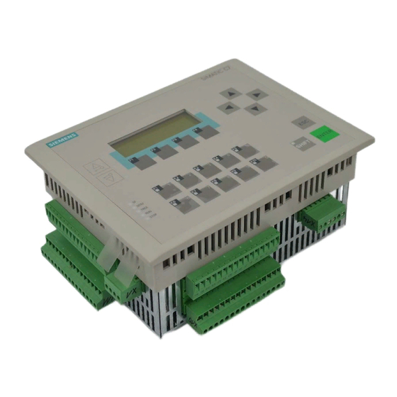
Product overview Design and Structure Figure 1-1 Front View of C7-613 C7-613 Control System A5E00138934-03... - Page 16 Product overview Components The C7-613 complete system consists of the following components: • SIMATIC CPU: S7-313C • Integrated HMI module (“C7-613 Panel” on Slot 4 in HW Config) with a keyboard and a four-line display with 20 characters or 10 graphical symbols per line Interfaces •...
-
Page 17: Controlling With The C7-613
Product overview 1.1.1 Controlling with the C7-613 Overview The user program controlling the process runs on the C7-613. The following functional units determine the mode of operation of the C7-613: Loading memory The loading memory is positioned on the Micro Memory Card (MMC). It includes the user program, the FBs needed for the HMI functions, and the DBs where the configuration data for the screens, messages, and info texts are stored. - Page 18 Product overview 1.1.2 Operator Control and Monitoring with the C7-613 Overview Operating modes, current process values, and faults can be displayed using the C7-613. In addition, inputs can be made on the C7-613 with the keyboard. Also, simple functions for machine diagnosis can be implemented with the C7-613. The C7-613 provides a number of standard functions.
- Page 19 Product overview Operational Messages Operational messages provide information about the current machine or process states during normal production operation. Operational messages may contain process values. Process values are displayed alphanumerically, e.g. “Motor speed 4500”. All operational messages are stored in the event buffer. Fault messages In contrast to operational messages, fault messages display critical machine states during the production run.
- Page 20 Product overview Languages Messages, screens, and info texts can be displayed in several languages. A maximum of five languages can be loaded to the C7-613 at the same time and made available to the operator for online selection. Standard/special screens and system messages are permanently stored in the following languages: •...
-
Page 21: Firmware Updates
Product overview Configuration/Process control Before the C7-613 is operated, it must be prepared for the visual display task. To this purpose you use the configuration interface to create a configuration for the HMI functions of the C7-613. The configuration data for screens, messages, and info texts are stored in DBs that have a defined structure. -
Page 22: Scope Of Functions
Product overview 1.1.4 Scope of Functions • RAM 48 KB – Of which available for applications: 32 KB – reserved for HMI functions: 16 KB • Loading memory and retentive memory of different sizes in the MMC • Integrated I/O –... -
Page 23: Product Scope And Accessories For The C7-613
• STEP 7 as from Version 5.2 + SPA + Hardware Update C7-613 V2.0 • The “Configuration Tools for SIMATIC C7-613” configuration CD C7-613 Control System A5E00138934-03... - Page 24 Product overview Accessories • Configuration CD “Configuration Tools for SIMATIC C7-613” Order Number: 6ES7613-0CA00-7AA0 The CD contains the following components: – Configuration interface in the languages German, English, French, Italian, Spanish – Manual in English, German, French, Italian, Spanish – Initial steps for commissioning (Getting Started) in English, German, French, Italian, Spanish –...
- Page 25 Product overview Options • I/O set for two modules, low profile (for I/O expansion directly on the device), Order No: 6ES7635-0AA00-6AA0 Consisting of: – A cable, approximately 0.25 m (for connecting the C7-636 to the S7 module) – Cable, approximately 0.08 m (for connecting an S7 module to an S7 module) –...
- Page 26 Product overview Documentation • Paper documentation Control system C7-613 , consisting of – C7-613 Control System Manual – Getting Started Language Order no. English 6ES7613-1CA00-8AB0 German 6ES7613-1CA00-8BB0 French 6ES7613-1CA00-8CB0 Spanish 6ES7613-1CA00-8DB0 Italian 6ES7613-1CA00-8EB0 • Documentation package C7-613 Control System, consisting of –...
-
Page 27: Installing And Wiring The C7-613
System-specific labels A template for the labeling strips (SLIDE613.DOC) is stored in Word format in the “Manuals” directory on the CD “Configuration Tools for SIMATIC C7-613”. You can design and print plant-specific labeling strips. To make your own labeling strips, use transparent film (0.1 to 0.15 mm thick) so that the LEDs of the function keys remain visible. - Page 28 Installing and Wiring the C7-613 To insert the labeling strip: Step Action Place the device with the front plate facing downward. Remove labeling strips that may have been previously inserted. With the labeling pointing downward, insert the new labeled strip into the slits of the front panel (use tweezers, if necessary).
-
Page 29: Mechanical Installation
Installing and Wiring the C7-613 Mechanical installation Mounting The C7-613 is intended for stationary and enclosed installation; for example, in a control cabinet door. Note You can only achieve the degree of protection IP65 if you follow steps 1 through 4 during installation. - Page 30 Installing and Wiring the C7-613 Switching cabinet door Mounting supports are not affixed to this side Figure 2-2 Mechanically Mounting the C7-613 79.3 198 + 1.0 Cutout in control cabinet door Figure 2-3 Dimension Diagrams for the C7-613 (Dimensions in mm) C7-613 Control System A5E00138934-03...
- Page 31 Installing and Wiring the C7-613 Figure 2-4 Dimension Diagrams for the C7-613 (Dimensions in mm) C7-613 Control System A5E00138934-03...
- Page 32 Installing and Wiring the C7-613 Figure 2-5 Dimension Diagrams for the C7-613 (Dimensions in mm) C7-613 Control System A5E00138934-03...
-
Page 33: Locating The C7-613 In A Mechanical Environment
Installing and Wiring the C7-613 Locating the C7-613 in a Mechanical Environment Locating the C7-613 When installing a C7-613, pay attention to the following: • The sheet of a switching panel door can be 2 to 4 mm thick. Make sure the sealing is seal-tight all round. -
Page 34: Setting Up The Electrical Configuration And Connector Pin Assignment
Caution For functional reasons, the connector pin assignment is not compatible to the predecessor products C7-621, C7-623, C7-626, C7-633 and C7-634. Note It is not possible to include the C7-613 in an ungrounded configuration Siemens SIMATIC C7 Micro Memory Card... - Page 35 Installing and Wiring the C7-613 Micro Memory Card connector X12 top Back- plane bus bottom (I/O bus) Supply Program- connector ming device conne-cti on (MPI) Analog output X14 I/O connector X13 top X10 bottom Figure 2-8 C7-613 with plugs and sockets, rear view Figure 2-9 C7-613 backplane labeling C7-613 Control System...
- Page 36 Installing and Wiring the C7-613 View from left I/O connector I/O connector Power supply connector Figure 2-10 C7-613 with plugs and sockets, view from left Supply Connector X1 Table 2-1 Supply Connector X1 Pin no. Signal Description Authorization input (for example, for external switch) Authorization input (for example, for external switch) Ground potential 24 V DC Supply voltage 24 V DC...
- Page 37 Installing and Wiring the C7-613 I/O connector X11 For the technological functions, the meaning of the inputs is described in the columns “Counting”, “Frequency Measuring” and “Pulse Width Modulation”. Table 2-2 Connector Pin Assignments for I/O Connector X11 Pin no. Signal / Description Counting...
- Page 38 Installing and Wiring the C7-613 I/O connector X12 For the technological functions, the meaning of the outputs is described in the columns “Counting”, “Frequency Measuring”, and “Pulse Width Modulation”. Table 2-3 Connector Pin Assignments for I/O Connector X12 Pin no. Signal / Description Counting...
- Page 39 Installing and Wiring the C7-613 Bottom view I/O connector X10 I/O connector X13 Analog output X14 Figure 2-11 C7-613 with plugs and sockets, bottom view I/O connector X10 Table 2-4 Connector Pin Assignment I/O Connector X10 Pin no. Signal / Description designation address...
- Page 40 Installing and Wiring the C7-613 I/O connector X13 Table 2-5 Connector Pin Assignment I/O Connector X13 Pin no. Signal Description Analog voltage input channel 0 Analog current input channel 0 Analog reference potential channel 0 Analog voltage input channel 1 Analog current input channel 1 Analog reference potential channel 1 Analog voltage input channel 2...
- Page 41 Installing and Wiring the C7-613 Side view Micro Memory Card Backplane bus (P bus) Programming Device Connection (MPI) Figure 2-12 C7-613 with plugs and sockets, view from right Programming Device Connection (MPI) X2 Table 2-7 Programming Device Connection (MPI) X2 Pin no.
- Page 42 Installing and Wiring the C7-613 C7-613Device Connections You can use the following connecting cables to connect the C7-613 to other components: Table 2-8 Connecting Cables for Connections to the C7-613 Connecting Cable Length Special Illustration Connection Features MPI Interface Programming device (PG) cable –...
-
Page 43: Guidelines For Fail-Safe Installation
Usage / routing of interference-proof cables • Only shielded cables are permitted for all analog signals. • Always use the standard cables supplied by Siemens. • Connect both ends of the shielding of the following cables: – Control signal cables –... - Page 44 Installing and Wiring the C7-613 Control cabinet installation Devices which may introduce external interference to the control cabinet should be mounted in the bottom area of the cabinet. Always mount the grounding busbar at a position close to the cable inlet, so that you can connect noise-carrying cables directly to earth potential.
-
Page 45: Connecting Shielded Cables
Installing and Wiring the C7-613 Connecting Shielded Cables Overview This section describes how to connect the shield of shielded signal lines to the ground. The cable shielding is connected to the grounding busbar, from there directly to the chassis ground of your C7-613 and to equipotential earth. Procedure Proceed as follows to install the grounding busbar supplied with the C7-613 and the shield terminals:... -
Page 46: Preventing Connector Interchanges Through Coding
Installing and Wiring the C7-613 Preventing Connector Interchanges through Coding Overview You can order a connector set with coding profiles and coding tabs as an accessory for the C7-613 (see accessories in Section 1.2). Caution Your C7-613 control system may be damaged if you unintentionally interchange the connectors. -
Page 47: Special Features Of The C7-613
Special Features of the C7-613 Differences to CPU 313C • Operating mode selection • Limited connection of additional S7-300 modules • Status display of the digital onboard I/O • Protective circuiting against overvoltage (± 24 V) at the analog current inputs •... -
Page 48: Operating Mode Selection
Special Features of the C7-613 Operating Mode Selection Siemens SIMATIC C7 SIMATIC C7 Mode selector keys with LEDs 5 VDC Status and FRCE error LEDs SHIFT STOP Figure 3-1 C7-613 Operating Mode Keys Changing the C7-613 Operating Mode The C7-613 modes RUN, STOP and MRES are selected by means of the mode selector keys: The C7-613 carries out a mode change whenever the key is pressed. - Page 49 Special Features of the C7-613 When mode selection is enabled, • you need to jumper the authorization inputs AT1 / AT2, • The key LEDs alongside the operating mode keys indicate the mode selector setting, • The current CPU operating status is indicated by the status LEDs When mode selection is disabled: •...
- Page 50 Special Features of the C7-613 Table 3-1 Operating Mode Keys Operating Description / procedure Mode The C7-613 executes the user program. Programs and data: • Read out from the C7-613 with the programming device/PC (C7 → programming device/PC) • Transmitted to the C7-613 and changed there (programming device/PC →...
-
Page 51: Status And Error Displays Of The C7-613
Special Features of the C7-613 Status and Error Displays of the C7-613 Meaning of the status and error displays The status and error displays are explained in the sequence in which they are arranged on the C7-613. Display Description Description SF (red) C7-613 group error Is lit when there are •... - Page 52 Special Features of the C7-613 Connecting Additional S7-300 Modules Directly on the Device 2-module I/O set Requirements: The C7-613 specific accessories “2-module I/O set” is available. Use the following procedure to connect the additional S7-300 modules: Step Action Screw the mounting plate to the backplane of the C7-613 housing. Install the C7-613 in the cabinet door.
- Page 53 Special Features of the C7-613 4-module I/O set Requirements: The C7-613-specific accessories “4-module I/O set” is available. Use the following procedure to connect the additional S7-300 modules: Step Action Screw the S7 DIN rail (190 mm) to the backplane of the C7-613. Install the C7-613 in the cabinet door.
- Page 54 Special Features of the C7-613 Connecting Additional S7-300 Modules at a Maximum Distance of 1.5 m Requirements: The C7-613 specific accessory “1.5 m cable” and a standard profile rail. Use the following procedure to connect the additional modules: Step Action Connect the C7-613 to the outermost module on the left-hand side using the connecting cable.
- Page 55 Special Features of the C7-613 Status Display of the Digital Onboard I/O I/O status display There are no LEDs for displaying the status of the C7-613 I/O. To display the status, you can use the configuration interface to generate process screens (see Figure 3-5 and Figure 3-6) or you can use Screens 2 and 3 provided in the sample program “ZXX31_01_C7-613”.
- Page 56 Special Features of the C7-613 C7-613 Control System 3-10 A5E00138934-03...
- Page 57 The configuration interface and the blocks needed for integrating the HMI functions into your user program are on the CD “Configuration Tools for SIMATIC C7-613”. During the installation process, the “C7 613 library” is set up where the blocks are stored.
- Page 58 To integrate the HMI functionality into your user program, FBs and UDTs are available for creating DBs with configuration data. They are located on the CD “Configuration Tools for SIMATIC C7-613” in the “C7 613” library. The FBs must be called cyclically or time-controlled in your program (recommendation: 20 to 50 ms).
- Page 59 Integration into the User Program FBs for the HMI Functions • FB “HMI API” The FB “HMI API” contains the following functions for executing the HMI functions: – Loading the screens, messages, and info texts to the memory of the integrated HMI module of the C7-613 –...
- Page 60 Integration into the User Program Calling the FBs The FBs are called with an associated instance DB. Example: Call “HMI API”, DB 11 Note If you have programmed one of the three HMI FBs in your program, do not call the same FB again in a program section with a different priority class, since the FB must not interrupt itself.
- Page 61 Integration into the User Program • For messages per language: – For a maximum of 64 messages: 1 DB with 9584 bytes – For more than 64 messages: 2 DBs with 9584 bytes each • For info texts per language: –...
- Page 62 Integration into the User Program Creating Configuration Data 4.3.1 Basis Overview The basic configuration, the configuration of the process screens, messages and info texts as well as the screen hierarchy are created by using the configuration interface. The configuration interface stores the configuration data in several DBs whose numbers are consecutive.
- Page 63 Integration into the User Program DB Structure The configuration interface creates the following DB structure: Table 4-1 DB Structure general DB Number Block name Block ID Description n–1 MENU MENU Contains the screen hierarchy CONFIG Configuration DB with the following retentive data: Last set language, character set, date format, system language,...
- Page 64 Integration into the User Program All 5 DBs are not always used for a language: • If you do not need more than 64 screens, only a single SCREEN DB is created. • If you do not need more than 64 messages, only a single MESSAGE DB is created.
- Page 65 Integration into the User Program Languages Use the language ID to specify for which language the blocks are intended. The language ID consists of a maximum of three characters (three-letter code/3LC). Standard/special screens and system messages The standard/special screens and the system messages are stored in the firmware of the C7-613 for the languages listed below.
- Page 66 Integration into the User Program 4.3.2 Creating Foreign-language Texts Scenarios The following scenarios are conceivable: • You configure a project in a different language to your installation. Example: You have a German configuration interface and want to create a French project. •...
- Page 67 Integration into the User Program 4.3.3 Creating Asian Texts Precondition If you create a project with Asian text, you must have an Asian Windows system or Windows 2000 multilingual as the operating system. Only under these Windows systems can you access the required character sets. The “Input Method Editor“...
- Page 68 Integration into the User Program 4.3.4 Integrating the HMI FBs and DBs into a User Program To create the program, do the following: Step Action In SIMATIC Manager, open the “C7 613” library and copy the following objects to the block container of your project. •...
- Page 69 Integration into the User Program 4.3.5 Basic Parameter Assignment The basic parameter assignment (configuration) is created by using the configuration interface. The configuration interface is used to specify the basic parameter assignment valid for all the languages. The basic parameter assignment is stored in the “CONFIG” configuration DB.
- Page 70 Integration into the User Program 4.3.6 Creating Process Screens Process screens are created by using the configuration interface. Each screen consists of 4 lines with 20 characters each (10 graphical symbols for Chinese, Japanese and Korean). A maximum of eight variables per screen can be specified for inputting and outputting data.
- Page 71 Integration into the User Program 4.3.7 Creating Messages Messages are created by using the configuration interface. Each message consists of 4 lines with 20 characters each (10 graphical symbols for Chinese, Japanese and Korean). A maximum of four variables per message can be specified for outputting of data. A message is configured if at least one character is edited in the static text.
- Page 72 Integration into the User Program 4.3.8 Variable in Process Screens and Messages Observe the following notes if you use variables in process screens or messages: Note If you define a variable that does not exist, the C7-613 switches to STOP mode when this variable is accessed.
- Page 73 Integration into the User Program 4.3.9 Creating Info Texts Info texts are created by using the configuration interface. Each info text consists of 4 lines with 20 characters each (10 graphical symbols for Chinese, Japanese and Korean). An info text can be assigned to one or more screens. An info text is configured when at least one character has been edited in the static text.
- Page 74 Integration into the User Program Figure 4-2 uses an example to show the transition possibilities within a screen hierarchy. Info text m Screen Info text m Info text m Info text m Screen Info text m Info text m Screen Info text Screen Info text m...
- Page 75 Integration into the User Program Converting Your Version 1 Project into a Version 2 Project Requirements • The DBs of the Version 1 projects have to belong to the C7_613 family and have a version <2.0. (See Object properties of the DBs, General Tab – Part 2) •...
-
Page 76: Fb "Hmi Api" For The Basic Hmi Functions
Integration into the User Program FB “HMI API” for the Basic HMI Functions Function The “HMI API” FB contains the essential functions for running the HMI functions. The FB “HMI API” has to be called cyclically or time-controlled in your program. Generation In SIMATIC Manager, open the “C7 613”... - Page 77 Integration into the User Program Table 4-3 Parameters of the “HMI API” FB, continued Parameter Declaration Data Type Memory Description Area RETVAL OUTPUT M, D, L, A Return value; provides information about possible errors and the status of the HMI functions. The return values are described in Appendix B.1 ADDINFO...
-
Page 78: Led Activation (Leds)
Integration into the User Program 4.5.1 LED Activation (LEDS) The LEDs in the C7-613 function keys can be activated from the user program. This makes it possible, for example, to signal to the operator with an illuminated LED which key he is supposed to press, depending on the situation. Transfer The LED image is updated each time the “HMI API”... -
Page 79: Keyboard Image (Keys)
Integration into the User Program 4.5.2 Keyboard Image (KEYS) Key activation can be transmitted to the user program and evaluated there. Thus, an action such as switching on a motor can be initiated. Transfer Transmission of the keyboard image is filtered depending on the state of the C7-613. - Page 80 Integration into the User Program Table 4-4 Relaying Key Operations, continued State C7-613 Relay Function keys Screen level (K-keys) Screen level in input mode with cursor Screen level in input mode with K-keys Standard/special screen Standard/special screen in input mode with cursor Standard/special screen in input mode with K-keys...
-
Page 81: Example For Evaluating The Keyboard Group Bit
Integration into the User Program Keyboard Group Bit The keyboard group bit is used as a check bit. Each time the keyboard image changes, it is set to “1”. After the data area has been evaluated, the user program should reset it. By reading keyboard the group bit, it can be determined in the user program whether the image of the system keyboard has changed. - Page 82 Integration into the User Program 4.5.3 Job Compartment (JOB_ID, JOB_PAR1, JOB_PAR2, JOB_PAR3) Job Compartment You can initiate control jobs for HMI functions from the user program using the job compartment. The job compartment consists of four words. The job number (JOB_ID) is located in the first word of the job compartment. The job number can be entered only indirectly.
- Page 83 Integration into the User Program Table 4-6 Control Jobs (JOB_ID) including Parameters, continued Function Screen selection Note: It is not possible to select a process screen/special screen if an object with a higher display priority (see Section 5.8) is displayed at the moment. The request is terminated with the error information “880B.
-
Page 84: Fb "Hmi Event" For The Message Output
Integration into the User Program FB “HMI EVENT” for the message output Function The “HMI EVENT” FB manages the incoming operational messages and fault messages and checks the acknowledgement of fault messages. If a fault message exists, it is output at the display as it was created by you by using the configuration interface. -
Page 85: Operational Messages And Fault Messages
Integration into the User Program 4.6.1 Operational Messages and Fault Messages Triggering Messages Messages are triggered by setting a bit in the message area. The position of the message area is specified with the “EVENTS” parameter. Message Area A message area can be specified for messages 1 to 127. As soon as the bit is set in the message area and the “EVENT”... - Page 86 Integration into the User Program Acknowledgement Fault messages are used to display extraordinary operating states. You therefore have to acknowledge the fault messages by setting a bit in the acknowledgement area. The position of the acknowledgement area is specified with the “ACKS” parameter.
-
Page 87: Structure Of The Event Buffer Db (Event_Buffer)
Integration into the User Program The table below describes the sequence for fault message acknowledgement. Table 4-8 Sequence for Fault Message Acknowledgement Step Action Response Description The user program The FB resets the associated A fault message has sets the fault acknowledgement bit. -
Page 88: Structure Of The Event Buffer Db
Integration into the User Program Structure and Description Table 4-9 Structure of the Event Buffer DB Address Name Type Description EVENT[1].NUMBER BYTE Message number The first message is the most recent message EVENT[1].STATE CHAR Status of message “K”=coming “G”=going “Q”=acknowledged EVENT[1].PVARS[1] DWORD Value of Process Variable 1 at the time... -
Page 89: Fb "Hmi Menu" For The Screen Hierarchy
Integration into the User Program FB “HMI MENU” for the Screen Hierarchy Function The “HMI MENU” FB provides support for the screen hierarchy.To accomplish this, the FB fetches information from the “MENU_DB” DB (see Section 4.3.10) regarding which key is to display which screen or which info text, and calls the corresponding objects. - Page 90 Integration into the User Program C7-613 Control System 4-34 A5E00138934-03...
-
Page 91: Operating The C7-613
Keyboard Keyboard Design The layout of the keys on the C7-613 is ergonomically tailored with respect to distribution and color composition for operator prompts in the various operating modes of the device Siemens SIMATIC C7 SIMATIC C7 Operating mode keys... -
Page 92: Function Of The System Keys
Operating the C7-613 Key Labeling and Key Function The C7-613 is operated using the keyboard. The keyboard has four different functional blocks (refer to Figure 5-1): • System keys • Function keys (K-keys) • Softkeys (F-keys) • Operating mode keys System keys The keypad with the system keys is highlighted in Figure 5-1. - Page 93 Operating the C7-613 Table 5-1 Function of the System Keys, continued Function Description Cursor Keys By pressing the cursor keys you can • Move within a screen either character-by-character or field-by-field to the left, the right, down, or up, depending on the operation required •...
-
Page 94: Operator Control Levels
After the configuration has been loaded, the idle message is displayed. = Selection of SIMATIC C7-613 Vx.xx Figure 5-2 C7-613 Idle Message If you have configured the Message 0 , Message 0 is displayed instead of the idle message. - Page 95 Operating the C7-613 the basic screen. From here, you branch to other screens, depending on the configuration. In screens you can • View current process values, • Enter values, • Trigger functions via softkeys. The linking of individual screens is referred to as the screen hierarchy (see Section 4.7).
- Page 96 Operating the C7-613 Forced Change to the Message Level The screen level is exited automatically as soon as a system message or fault message is pending for display. The C7-613 then switches to the message level to display such a message. This level cannot be exited as long as a system message or an unacknowledged fault message is displayed.
-
Page 97: Entering Values
Operating the C7-613 Entering Values Overview Numerical values are entered in the C7-613 in entry fields of screens and special screens (for example, when entering a password). Values can be entered alternatively • With function keys, • With cursor keys. The selection is specified by using the configuration interface. -
Page 98: Entry Using Function Keys (K-Keys)
Operating the C7-613 Example: You have specified 5 as the length of the field (Decimals_Length). You have selected “Byte” as the data type (Access Code). Display Value in the Byte Prior to entry 11111 11111111 After entering the value 11110 11110 00011110 Limits... - Page 99 Operating the C7-613 When entering values, do the following: Step Action Result Using the cursor keys, select the desired entry The cursor is located on the field within the screen. input field. The LED of the SHIFT key is Press the SHIFT key in order to illuminated (SHIFT Lock).
-
Page 100: Entry Using Cursor Keys
Operating the C7-613 5.3.2 Entry Using Cursor Keys In fields where a value may be entered by the operator, the numerical value is entered on a character-by-character basis using the cursor keys (SHIFT Lock). When entering values, do the following: Step Action Result... - Page 101 Operating the C7-613 Step Action Result As soon as you begin with the input, you cannot exit the respective field until you confirm or cancel the entry. The value is entered. The Confirm your entry with ENTER entry is terminated, and the SHIFT LED is turned off.
-
Page 102: Operator Input Using Standard/Special Screens
Operating the C7-613 Operator Input Using Standard/Special Screens Overview You can use the keyboard both to select various settings and execute functions. A variety of standard/special screens are available for the C7-613 for this purpose. For example, the event buffer can be called, or a password can be entered. There are two types of screens: •... - Page 103 Operating the C7-613 Screen Hierarchy of the Standard/Special Screens Figure 5-4 shows an overview of the existing screen hierarchy for standard/special screens. Detailed information regarding functions and operator input for the standard/special screens is provided in the corresponding sections of this manual . The numbers refer to the screen numbers, which are provided in the “OBJ_NO”...
- Page 104 . Step Action Result Switch the C7-613 to RUN mode. The idle message “Simatic C7-613 Vx.xx” is displayed. Press the “ENTER” key. The basic screen is displayed (see Figure 5-5). Using the softkeys below the Additional screens are displayed.
-
Page 105: Screens
Operating the C7-613 Screens Overview Process events (for example, processing machine or mixing station events) are displayed in screens and controlled as well (by operator inputs) on the C7-613. These screens are created application-specifically. Logically associated process values are recorded in screens, thus providing an overview of a process or a plant. - Page 106 Operating the C7-613 Components of a Screen A screen consists of the following components: • Static text The static texts contain explanations for the operator. They can also include information about the assignment of softkeys. • Input and output fields for the following: –...
-
Page 107: Messages
Operating the C7-613 Messages Overview Messages are used to indicate events and states in the control process on the C7-613 display. The messages have to be created beforehand, however (see Section 4.3.7). A message consists of at least a static text. Fault messages and operational messages can also contain up to four output variables. - Page 108 Operating the C7-613 • Fault messages – Are messages on faulty operations or state faults, e.g. “Motor temperature too high” or “Valve does not open”, – Fault messages are displayed immediately and appear as flashing messageson the display – Fault messages must always be acknowledged –...
- Page 109 Operating the C7-613 Event Buffer Fault and operational messages are entered in the event buffer of the C7-613. The event buffer is a ring buffer and can contain up to 256 messages. The event buffer is retained after a language change, a Reload application operation, CPU restart, POWER OFF, and general reset.
-
Page 110: Acknowledging Fault Messages
Operating the C7-613 Saving the Event Buffer to the DB In order to save and perform further work on the event buffer, it can be stored (256 entries maximum) in a DB (EVENT_BUFFER) on the MMC. You can save with the keyboard using a special screen or in the user program by means of a job request. -
Page 111: System Messages
Operating the C7-613 5.6.3 System Messages Overview System messages display internal operating states of the C7-613. They indicate maloperations or malfunctions, for example. Display of System Messages This type of message has the highest display priority (see Section 5.8). If a corresponding fault occurs in the C7-613, the object that is currently displayed is removed, and a system message is output instead. -
Page 112: Displaying Messages In The Message Level
Operating the C7-613 5.6.4 Displaying Messages in the Message Level Overview Pending (not yet gone) operational and fault messages are always output in the message level on the C7-613. Selecting the Message Level You access the message level from the screen level using a function key (K-key). To accomplish this, in your user program, place Job Request 51 for changing to the “Select message level”... -
Page 113: Viewing The Event Buffer
Operating the C7-613 5.6.5 Viewing the event buffer Overview Messages occurring are written to the event buffer. You can call up the event buffer to view the message history via special screens. Each status change (arrived/going/acknowledged) in a message leads to a new entry in the event buffer. - Page 114 Operating the C7-613 Table 5-5 Description of Example in Figure 5-8, continued Message Part Description Range A message has gone. 001/015 The displayed message is in Position 001 to 256 1 (most recent message). There are 15 messages in the event buffer #003 Message number...
-
Page 115: Selection Of Additional Information/Info Texts
Operating the C7-613 Selection of Additional Information/Info Texts For each message you can have additional information (message text, variables) and - if configured - an info text assigned to the message displayed. In order to select additional information and info text use the cursor keys (for details please refer to Section 5.6.6.). -
Page 116: Selection Of Additional Information And Info Texts
Operating the C7-613 5.6.6 Selection of Additional Information and Info Texts Selection of Additional Information Figure 5-9 shows how you can use the cursor keys to have additional information for every message displayed: <Fault > K 001/015 #003 Fault Plant1 30.04.02 17:45:04 Message Text No. - Page 117 Operating the C7-613 Selection of Info Texts Figure 5-10 shows how you can use the cursor keys to have one or more info texts which you have assigned to a message displayed. The info texts and their assignment to a specific message are specified by using the configuration interface.
-
Page 118: Number Of Messages In The Event Buffer (Quantity)
Operating the C7-613 5.6.7 Number of Messages in the Event Buffer (Quantity) Overview You determine the number of messages in the event buffer as follows: • By selecting the special screen “Messages > Quantity” • By means of the user program by calling the “HMI API” FB This ensures that you can carry out a backup in case of an imminent overflow of the event buffer. -
Page 119: Clearing Entries In The Event Buffer (Clear)
Operating the C7-613 5.6.8 Clearing Entries in the Event Buffer (Clear) Overview Operational and fault messages are automatically stored in the event buffer. The event buffer is laid out as a ring buffer and can contain up to 256 entries. There are two methods of clearing entries for operational or fault messages in the message buffer: •... -
Page 120: Saving The Event Buffer To The Loading Memory (Save)
Operating the C7-613 5.6.9 Saving the Event Buffer to the Loading Memory (Save) Overview In order to save and perform further work on the event buffer, it can be stored in a DB (EVENT_BUFFER) in the loading memory on the MMC. Arriving fault messages are displayed after the save is completed. -
Page 121: Info Texts
Operating the C7-613 Info Texts Overview You can create customized info texts. An info text can be assigned to one or more screens. Additional information can be provided for each screen in info texts. Info texts consist of static text only. In the C7-613, a maximum of 128 info texts can be specified. -
Page 122: Display Priority Of The Objects
Operating the C7-613 Display Priority of the Objects Objects that can be presented on the C7-613 can interrupt each other. Only objects with a higher display priority can interrupt objects with a lower display priority. Objects are listed below according to their display priority: •... -
Page 123: System Functions (System)
Operating the C7-613 System Functions (System) After you have loaded a configuration, you can use special screens to change the following C7-613 system settings specified by the configuration (see Section 4.3.5): • Language • Contrast During the startup phase, the modified configuration becomes effective with “Reload application”. -
Page 124: Language Switch (Language)
Operating the C7-613 5.9.2 Language Switch (Language) Setting the Language Messages, screens, and info texts can be displayed in several languages. Screens, messages and info texts can be downloaded in a maximum of 5 languages simultaneously and offered for online selection by the operator. The standard/special screens and the system messages are stored in the firmware of the C7-613 for the languages listed in Section 4.3. -
Page 125: Contrast Setting (Contrast)
Operating the C7-613 5.9.3 Contrast Setting (Contrast) Overview The contrast of the LCD display on the C7-613 can be changed with the special screen “Contrast”. The modified value is entered in the configuration DB (CONFIG). The value 6 is preset. Contrast setting To set the contrast: Step... -
Page 126: Password Editing (Password)
Operating the C7-613 5.10 Password Editing (Password) Overview To prevent unauthorized operation of the C7-613, you have the option to set up access protection for each process screen using passwords and password levels. Password protection for the function keys (K-keys) is not possible. The passwords can be specified during configuration, or they can be entered with the keyboard in the special screen “Edit”... -
Page 127: Password Levels And Access Rights
Operating the C7-613 Password Protection for Standard/Special Screens There is no password protection for standard/special screens. You can protect the functions of the special screens bydoing the following: • Prevent the output of the basic screen by branching to the standard/special screens: To do so, use the configuration interface to specify an initial screen. -
Page 128: Entering The Password (Edit )
Operating the C7-613 5.10.3 Entering the Password (Edit ) Overview Passwords can be entered in the configuration (refer to Section 4.3.5) or via the special screen Password > Edit. Depending on your configuration you enter the values by using either the function keys or the cursor keys (refer to Section 5.3). - Page 129 Operating the C7-613 Assigning the password and password list You can assign passwords only to those password levels that are equal to or less than your password level. A password and a password level are assigned as follows: Step Action Result In the password list, select the corresponding The cursor is located in the...
-
Page 130: Logging In
Operating the C7-613 5.10.4 Logging In Login for the C7-613 If you call up a screen for which the current password level is too low, you have to log in at the C7-613. In this case, the prompt to enter a password is displayed automatically. -
Page 131: Maintenance
Maintenance The C7-613 is designed for low maintenance operation. Maintenance is required only in the following areas: • Cleaning of the display at regular intervals • Replacement of a faulty device C7-613 Control System A5E00138934-03... -
Page 132: Cleaning The Display
Maintenance Cleaning the Display Preparation Clean the display of your device at regular intervals using a damp cloth. Perform the cleaning while the device is switched off. This ensures that you do not unintentionally delete functions. Cleaning agent Use only water and cleaning solution or a foaming screen cleaner to dampen the cloth. - Page 133 Maintenance Uninstallation Step Action You do not need to take special measures to back up the user program of the C7–613. It is saved as a non-volatile program on the MMC. If you want to save the event buffer, you must first store it in a DB (EVENT_BUFFER) on the MMC (see Section 5.6.1).
- Page 134 Maintenance C7-613 Control System A5E00138934-03...
-
Page 135: Technical Data
Technical data Technical Specifications for Control System Table A-1 Technical Specifications for C7-613 General data Order no. 6ES7613-1CA01-0AE3 Dimensions: 215 x 165 x 79.3 mm (H x W x D) Cut-out dimensions: (198 + 1) mm x (148 +1 ) mm Mounting depth for 2-module I/O 144 mm (measured from outer edge of sheet metal cut-out) set:... - Page 136 Safety Standard references DIN EN 61131-2 corresponds to IEC 61131-2 Protection against ingress of solid foreign bodies and water IP65, to IEC 60529, NEMA 4X • Front panel IP20, to IEC 60529 • Housing Electromagnetic compatibility (EMC) Emitted interference Limit class in accordance with EN55011 Cable-fed disturbances on DC ±2 kV (to IEC 61000-4-4;...
- Page 137 Technical data Mechanical environmental conditions Vibration Tested in accordance with IEC 60068-2-6 • Operation 10 Hz to 58 Hz, amplitude 0.075 58 Hz to 150 Hz, acceleration 9.8 m/s • Storage/transport in 5 Hz to 9 Hz, amplitude 3.5 mm packaging 9 Hz to 500 Hz, acceleration 9.8 m/s Shock test...
-
Page 138: Hmi Functionality
HMI functionality Table A-2 HMI Functions for C7-613 Function Value Display • Technology STN LC • Number of lines • Number of characters per line • Number of graphical symbols per line • Contrast setting Screens • Maximum number • Maximum number of characters per screen 80 characters •... -
Page 139: Technical Specifications For Cpu
Technical data Technical Specifications for CPU Memory User memory • Integrated 48 KB – Of which 32 KB for user program – Of which 16 KB required for the FBs for the HMI functions • Expandable Loading memory Pluggable via MMC (max. 8 MB) Backup Ensured with MMC (maintenance-free) Execution times... - Page 140 Data areas and their retentivity Total retentive data area (including memory bits; timers; counters) Bit memory 256 bytes • Retentivity Adjustable • Default retentivity MB 0 to MB 15 Clock memory 8 (1 memory byte) Data blocks Max. 511 (from DB 1 to DB 511) •...
- Page 141 Technical data Configuration Rack Max. 1 Modules in the rack Max. 4 Number of DP masters • Integrated None • by means of CP Max. 2 Function modules and communication processors that can be operated • Max. 4 • CP (PtP) Max.
- Page 142 Testing and commissioning functions Status/control variable • Variables Inputs, outputs, flags, DBs, timers, counters • Number of variables Max. 30 – Of those as status Max. 30 variable – Of those as control Max. 14 variables Force • Variables Inputs, outputs •...
- Page 143 Technical data Communication functions Number of connections Max. 8 • Can be used for Max. 7 PG communication – Reserved (default) – Adjustable From 1 to 7 • Can be used for Max. 7 OP communication – Reserved (default) – Adjustable From 1 to 7 •...
- Page 144 Programming Programming language LAD/FBD/STL Stored instructions See the instruction list Nesting levels System functions (SFCs) See the instruction list System function blocks (SFBs) See the instruction list User program security Integrated I/O Default addresses • Digital inputs 124.0 to 126.7 •...
-
Page 145: Technical Specifications For Integrated I/O
Technical data Technical Specifications for Integrated I/O Digital inputs Number Number of inputs • inputs usable for technological functions Cable length • Unshielded – For standard DI Maximum 600 m – Technological functions non-shielded cables not allowed • Shielded – For standard DI Maximum 1,000 m (109 yd.) –... - Page 146 Status, interrupts, diagnostics • Interrupts Yes, if the corresponding channel is configured as an interrupt input • For application of technological functions, refer to “S7-300 Programmable Controllers CPU31xC Technological Functions” manual. • Diagnostic functions No diagnostics when operated as standard I/O •...
- Page 147 Technical data Digital outputs Note Technological functions utilize fast digital outputs. These outputs must only be connected to resistive loads. Number Number of outputs • Of those are high-speed outputs Cable length • Unshielded Maximum 600 m • Shielded Maximum 1,000 m (109 yd.) Voltage, currents, potentials Rated load voltage L+ 24 VDC...
- Page 148 Status, interrupts, diagnostics • Interrupts No interrupts when operated as standard I/O • When using the technological functions, cf. S7-300 Programmable Controller, CPU31xC Technological Functions” manual • Diagnostic functions No diagnostics when operated as standard I/O • When using the technological functions, cf.
- Page 149 Technical data Analog inputs Number Number of inputs • Current / voltage input 4 channels • Resistance input 1 channel Cable length • Shielded Maximum 100 m (109 yd.) Voltage, currents, potentials Resistance input • No-load voltage 2.5 V, typically •...
- Page 150 Interference suppression, error limits Interference suppression at f = n × (f1 ±1 %) (f1 = interference frequency), n = 1, 2 • Common mode interference > 40 dB (VCM < 1.0 V) • Push-pull interference (peak value of the >...
- Page 151 Technical data Encoder selection data Input ranges (rated values)/input resistance • Voltage ±10 V/100 kΩ 0 V to 10 V/100 kΩ • Current ±20 mA / 50 Ω 0 mA to 20 mA/50 Ω 4 mA to 20 mA/50 Ω •...
- Page 152 Analog outputs Number Number of outputs Cable length Shielded cable length Maximum 200 m (109 yd.) Voltage, currents, potentials Rated load voltage L+ 24 VDC • Polarity reversal protection Galvanic isolation • Between channels and P-bus • Between channels Permissible potential difference •...
- Page 153 Technical data Interference suppression, error limits Crosstalk between the outputs > 60 dB Operational error limit (across the temperature range, relative to output range) • Voltage/current ±1 % Basic error limits (operational error limit at 25 °C, relative to output range ) •...
- Page 154 Data for selecting an actuator Output range (rated values) • Voltage ±10 V 0 V to 10 V • Current ±20 mA 0 mA to 20 mA 4 mA to 20 mA Load resistance (in the rated range of the output) •...
-
Page 155: Notes On The Power Supply
Technical data Notes on the power supply 24 VDC Supply For the C7-613, the entire 24 VDC power supply (operating voltage, load voltage, relay supply, etc.) must be generated as safety extra-low voltage (SELV). Warning Personal injury and property damage can occur. If you do not configure the 24 VDC power supply of the C7-613 correctly, the components of your automation system may be damaged and personal injury may occur. -
Page 156: Approvals
Approvals Approvals for USA and Canada Note Which one of the approvals (UL/CSA or cULus) listed below is relevant for your product is indicated on the rating plate. UL approval Underwriters Laboratories Inc. to • UL 508 (Industrial Control Equipment) CSA approval Canadian Standards Association to •... - Page 157 Technical data FM Approval FM-Standards No. 3611, 3600, 3810 APPROVED for use in Class I, Division 2, Group A, B, C, D indoor hazardous locations. APPROVED Class I, Division 2, Group IIC Warning Personal injury and property damage can occur. In a potentially explosive environment, there is a risk of personal injury and damage to material if you disconnect a connector while the system is in operation.
-
Page 158: Notes On Ce Mark
The EC declarations of conformity and their associated documentation are available for the competent authorities in accordance with the above-mentioned EC Guideline, Article 10 (1) at the following address: Siemens Aktiengesellschaft Automation technology A&D AS RD 4 PO box 1963... -
Page 159: Notes For Machine Manufacturers
Technical data Notes for Machine Manufacturers Introduction The SIMATIC automation system is not a machine in the sense of the EC guideline “Machinery”. Consequently, no declaration of conformity exists with regard to the EC guideline 89/392/EEC “Machinery”. EC Guideline 89/392/EEC ”Machinery” EC guideline 89/392/EEC “Machinery”... - Page 160 C7-613 Control System A-26 A5E00138934-03...
-
Page 161: Error Information For Hmi Fbs And System Messages
Error Information for HMI FBs and System Messages Error Information for HMI FBs Introduction This chapter describes error information for HMI FBs, including when error information occurs and how the cause of the error can be removed. The FBs use the error code (return value “RETVAL” parameter) to supply information about the errors and the status of HMI functions or the integrated HMI module. - Page 162 Error information of the “HMI API” FB Error Code Cause Remedy (W#16#...) 7000 Integrated HMI module of C7-613 This is a status message that provides is being initialized. information about the function that is currently being performed. The integrated HMI module of the C7-613 is undergoing a cold restart.
- Page 163 Error Information for HMI FBs and System Messages Error Code Cause Remedy (W#16#...) 8102 Parameter 2 (“JOB_PAR2”) of the Valid values for this job can be found in job compartment has an invalid the description of the controller tasks value for this job. (refer to Section 4.5.3).
-
Page 164: C Configuration Dbs
Error Code Cause Remedy (W#16#...) 8223 The DB for backing up the event Check to determine whether the buffer on the MMC that is “unlinked” attribute has been selected for specified in the “EVENT_DB” the specified DB. To select the “unlinked” parameter does not have the attribute, refer to the STEP 7 Online “unlinked”... - Page 165 Error Information for HMI FBs and System Messages Error Code Cause Remedy (W#16#...) 880A A selected process Check whether a configuration is screen/special screen or an info available for the selected object. A text is not available. process screen or info text is configured if at least one character is edited in the static text.
- Page 166 Error information of the “HMI EVENT” FB Error Cause Remedy ID(W#16#...) 7000 Integrated HMI module of C7-613 This is a status message that provides is being initialized. information about the function that is currently being performed. The Incoming messages are delayed. integrated HMI module of the C7-613 is undergoing a cold restart.
- Page 167 Error Information for HMI FBs and System Messages Error Cause Remedy ID(W#16#...) 8212 The DB specified in the “API_DB” Check to determine whether the parameter is too short. specified DB is the instance DB of the “HMI-API” FB. If necessary, recreate the instance DB. 8213 The DB specified in the “API_DB”...
- Page 168 Error Cause Remedy ID(W#16#...) 8231 The access type of the Use an area pointer of the following acknowledgement area pointer types: BOOL; BYTE; WORD; INT; cannot be interpreted. DWORD; DINT For example: P#M20.0 BOOL 128, P#M20.0 BYTE 16, P#M20.0 WORD 8, P#M20.0 INT 8, P#M20.0 DWORD 4, P#M20.0 DINT 4...
- Page 169 Error Information for HMI FBs and System Messages Error information of the “HMI MENU” FB Error Cause Remedy ID(W#16#...) 7000 The integrated HMI module of This is a status message that provides C7-613 is being initialized. information about the function that is currently being performed.
- Page 170 Error Cause Remedy ID(W#16#...) 8212 The DB specified in the “API_DB” Check to determine whether the parameter is too short. specified DB is the instance DB of the “HMI-API” FB. If necessary, recreate the instance DB. 8213 The DB specified in the “API_DB” Check to determine whether the parameter is not available in the specified DB is loaded.
- Page 171 C7-613 is being information about the function that is currently V..(Version) initialized. being performed. The integrated HMI module of SIMATIC C7-613 the C7-613 is undergoing a cold restart. No Startup additional action is required. $ 001 There are no data blocks Load the data blocks with the configuration data with configuration data.
- Page 172 System Message Cause Remedy $ 003 There are no messages in – the event buffer. The event buffer is empty. $ 004 There is an error in a data Eliminate the parameter assignment error. You block with configuration can obtain more detailed information in the Parameter assignment data.
- Page 173 Error Information for HMI FBs and System Messages System Message Cause Remedy $ 016 The input value is less Repeat the entry with a higher value. than the lower limit value. Entry < lower limit value The original value is retained.
-
Page 174: (Upper Number Decimal Value, Lower Number Hexadecimal Value
Conversion Tables for Decimal/Hexadecimal Table B-1 Conversion table for screen numbers/info text numbers (upper number decimal value, lower number hexadecimal value) C7-613 Control System B-14 A5E00138934-03... - Page 175 Error Information for HMI FBs and System Messages Table B-2 Screen Position (Top: Decimal Value; Bottom: Hexadecimal Value) C7-613 Control System B-15 A5E00138934-03...
- Page 176 C7-613 Control System B-16 A5E00138934-03...
-
Page 177: Configuration Db "Config
Configuration DBs Configuration DB “CONFIG” Structure and Description Table C-1 Structure of the Configuration DB Address Name Type Description DB_HEADER.HEAD.ID STRING[6] The block ID “CFG” identifies the DB as configuration DB DB_HEADER.HEAD.LANGUAGE STRING[3] Language ID in 3-letter code DB_HEADER.HEAD.AMOUNTOBJ Number of objects 16 to 31 Reserved BYTE... - Page 178 Table C-1 Structure of the Configuration DB, continued Address Name Type Description CFG_DATA.PASSWORDS[2].PASS DINT Passwort 2 100 to 99 999 999, 0 = No password CFG_DATA.PASSWORDS[2]. BYTE Reserved, must be 0 Reserved CFG_DATA.PASSWORDS[2].LEVEL BYTE Password level 1 to 3 No password is needed for password level 0 CFG_DATA.PASSWORDS[3].PASS DINT...
-
Page 179: Structure Of Configuration Db, Optional Part
Configuration DBs Table C-1 Structure of the Configuration DB, continued Address Name Type Description CFG_DATA.PASSWORDS[8].LEVEL BYTE Password level 1 to 3 No password is needed for password level 0 CFG_DATA.PASSWORDS[9].PASS DINT Password 9 100 to 99 999 999, 0 = No password CFG_DATA.PASSWORDS[9]. - Page 180 Table C-2 Structure of configuration DB, optional part, continued Address Name Type Description LANG[1].SUBST_MSG_STATIC[3] STRING[20] Static text of the 3rd line from the system message $002 LANG[1].SUBST_MSG_STATIC[4] STRING[20] Static text of the 4th line from the system message $002 216 to LANG[2]..
-
Page 181: Process Screen Db "Screen
Configuration DBs Process screen DB “SCREEN” Structure and Description Table C-3 Structure of DB for Process Screens Address Name Type Description DB_HEADER.HEAD.ID STRING[6] The block ID “SCREEN” identifies the DB as a DB for storing screens. DB_HEADER.HEAD.LANGUAGE STRING[3] Language ID in 3-letter code DB_HEADER.HEAD.AMOUNTOBJ Number of objects 16 to 31... - Page 182 Table C-3 Structure of DB for Process Screens, continued Address Name Type Description SCREEN[0].PIC_VAR[1]. BYTE Length of field and number of decimal DECIMALS_LENGTH places. For numbers with decimal places, the length of the field must be at least two times greater than the number of decimal places.
- Page 183 Configuration DBs Table C-3 Structure of DB for Process Screens, continued Address Name Type Description SCREEN[0].PIC_VAR[1].ACCESS CHAR Data type “X”=BOOL “C”=CHAR “B”=BYTE “I”=INT “L”=DINT “W”=WORD “D”=DWORD SCREEN[0].PIC_VAR[1].BITNO BYTE Bit number 0 to 7; must be 0 for all data types except “X”.
-
Page 184: Example For A Created Process Screen
Example for a created process screen Table C-4 Example for a created process screen Address Name Type Actual Value Description DB_HEADER.HEAD.ID STRING[6] “SCREEN“ Block ID DB_HEADER.HEAD.LANGUAGE STRING[3] “GER“ Language ID DB_HEADER.HEAD.AMOUNTOBJ BYTE Number of objects 16 to 31 DB_HEADER.HEAD.Reserved[..] Reserved SCREEN[0].PIC_.INFO.INFO BYTE Reserved... - Page 185 Configuration DBs Table C-4 Example for a created process screen, continued Address Name Type Actual Value Description SCREEN[0].PIC_VAR[1].ACCESS CHAR “I” Data Type “I”=Integer SCREEN[0].PIC_VAR[1].BITNO BYTE Bit Number SCREEN[0].PIC_VAR[1].UPPERLIM DINT Upper limit: no limit monitoring SCREEN[0].PIC_VAR[1].LOWERLIM DINT Lower limit: no limit monitoring ..
- Page 186 Message DB “MESSAGE” Structure and Description Table C-5 Structure of DB for Messages Address Name Type Description DB_HEADER.HEAD.ID STRING[6] The block ID “MESSAG” identifies the DB as a DB for storing messages. DB_HEADER.HEAD.LANGUAGE STRING[3] Language ID in 3-letter code DB_HEADER.HEAD.AMOUNTOBJ Number of objects 16 to 31 DB_HEADER.HEAD.Reserved[..]...
-
Page 187: Structure Of Db For Messages
Configuration DBs Table C-5 Structure of DB for Messages, continued Address Name Type Description MESSAGE[0].MSG_VAR[1]. BYTE Length of field and number of decimal DECIMALS_LENGTH places. For numbers with decimal places, the length of the field must be at least two times greater than the number of decimal places. - Page 188 Table C-5 Structure of DB for Messages, continued Address Name Type Description 150 to MESSAGE[0].MSG_VAR[2]. Description for Variable 2 160 to MESSAGE[0].MSG_VAR[3]. Description for Variable 3 170 to MESSAGE[0].MSG_VAR[4]. Description for Variable 4 180 to MESSAGE[1]... Description for Message 1 9356 to MESSAGE[63]...
-
Page 189: Info Text-Db "Info
Configuration DBs Info text-DB “INFO” Structure and Description Table C-6 Structure of DB for Info Texts Address Name Type Description DB_HEADER.HEAD.ID STRING[6] The block ID “INFO” identifies the DB as a DB for storing info texts. DB_HEADER.HEAD.LANGUAGE STRING[3] Language ID in 3-letter code DB_HEADER.HEAD.AMOUNTOBJ Number of objects 16 to 31... -
Page 190: Screen Hierarchy Db "Menu
Screen hierarchy DB “MENU” Structure and Description Table C-7 Structure of DB for the Screen Hierarchy Address Name Type Description DB_HEADER.HEAD.ID STRING[6] The block ID “MENU” identifies the DB as a DB for storing the screen hierarchy. DB_HEADER.HEAD.LANGUAGE STRING[3] Language ID in 3-letter code DB_HEADER.HEAD.AMOUNTOBJ Reserved, no entry required. - Page 191 Configuration DBs Table C-7 Structure of DB for the Screen Hierarchy, continued Address Name Type Description MENU[0].SCR_F1 BYTE No. of the screen/info text called up when “F1” is pressed. 0 to 127 process screens Special screens (for permissible numbers, refer to Section 4.5.3) 0 to 127 info texts 255 = No screen change MENU[0].SCR_F2...
- Page 192 C7-613 Control System C-16 A5E00138934-03...
- Page 193 Index Cable, for I/O expansion, 2-16 Cable 1.5 m, 1-11 Access rights, 5-37 Cables, interference-proof installation, 2-17 Accessories, 1-9, 1-10 Calling FBs, 4-4 Acknowledgement, 4-30 CD, 1-10 Acknowledgement area, 4-30 installing, 4-1 Acknowledgement bit, 4-30 CE mark, A-24 Acknowledgement sequence, 4-31 Changing ADDINFO, B-1 to the message level, 5-5...
- Page 194 Index Cut-out dimensions, A-1 Event buffer-DB, 4-31 EVENT_BUFFER DB, 4-31 Data areas LED-image, 4-22 Fail-safe installation, 2-17 System keyboard-image, 4-24 Fault messages, 1-5, 4-29, 5-17 Date setting, 5-35 acknowledging, 5-20 DB structure, 4-7 FB HMI API, 4-20 DBs with configuration data, 4-2 FB HMI EVENT, 4-28 Decimal places, 5-7 FB HMI MENU, 4-33...
- Page 195 Index I/O status display, 3-9 Idle message, 5-4 Labeling strips, 2-1 INFO DB, C-13 Language, setting, 5-34 Info text, 1-5, 5-31 Language ID, 4-9 creating, 4-17 Language keyboard, 4-10 Max. length, A-4 Language switch, 5-34 Max. number, A-4 Languages, 1-6, 4-9 selecting, 5-31 Info text-DB, C-13 image, 4-22...
- Page 196 Index Mounting supports, 2-3 Power-up time, 4-5 MPI, 2-15 Process screen-DB, C-5 MPI cable, 1-11 Program structure, 4-2 MRES, 3-4 Programming, 1-3 Programming device (PG)-cable, 2-16 Programming language, 1-3 Programming device-connection, 2-15 Notes on power supply, A-22 Notes on the power supply, A-21 Number of characters per line, A-4 Number of lines on display, A-4 RAM, Size, 1-8...
- Page 197 Index Spare parts, 1-11 Technological functions, 1-8 Special screens, 4-27, 5-12 Time setting, 5-35 Standard functions, operator input, 5-12 Standard screens, 5-12 screen hierarchy, 5-13 Starting a job, 4-26 UDTs, 4-12 Status displays, 3-5 UL, Approval, A-22 Status messages, 5-18 Undoing field entries, 5-2 Status-LEDs, 3-3 Ungrounded configuration, 2-8...
-
Page 198: Index
Index C7-613 Control System Index-6 A5E00138934-03... - Page 199 Non--retentive data blocks and code blocks can be loaded to the maximum limit of the working memory. Retentive data blocks can be loaded to the maximum retentive limit of the working memory (see the following table). Copyright Siemens AG 2006 Siemens Aktiengesellschaft A5E00861679-01...
- Page 200 Product Information A5E00861679-01...
Need help?
Do you have a question about the SIMATIC C7-613 and is the answer not in the manual?
Questions and answers
SIMATIC C7-613, onboard lub oil purifier control panel , the display stopped working . we need to replace the conplete unit or any particular card will resolve the issue
The display issue on the Siemens SIMATIC C7-613 cannot be resolved by replacing a specific card. The C7-613 is not designed for on-site repair, so if it is defective, the entire unit must be replaced.
This answer is automatically generated