Table of Contents
Advertisement
Advertisement
Table of Contents

Subscribe to Our Youtube Channel
Related Manuals for Siemens SIMATIC C7-626


Summary of Contents for Siemens SIMATIC C7-626
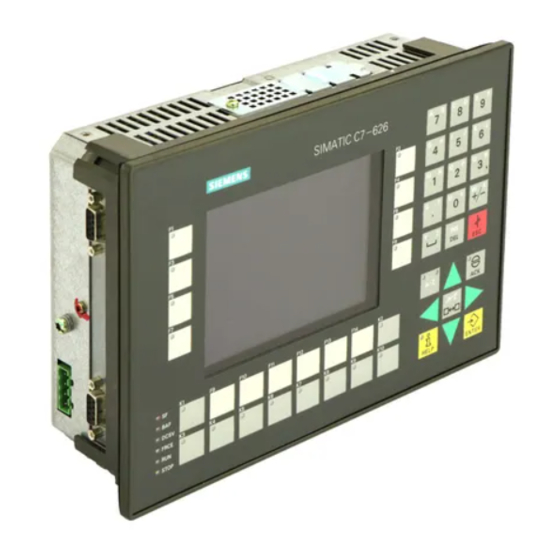
- Page 1 DATASHEET SIEMENS KEYPAD 6ES7626-2AG00-0AE3 OTHER SYMBOLS: RGB ELEKTRONIKA AGACIAK CIACIEK SPÓŁKA JAWNA Jana Dlugosza 2-6 Street 51-162 Wrocław www.rgbelektronika.pl Poland biuro@rgbelektronika.pl +48 71 325 15 05 www.rgbautomatyka.pl www.rgbautomatyka.pl www.rgbelektronika.pl...
- Page 2 YOUR PARTNER IN MAINTENANCE Repair this product with RGB ELEKTRONIKA ORDER A DIAGNOSIS LINEAR ENCODERS SYSTEMS INDUSTRIAL COMPUTERS ENCODERS CONTROLS SERVO AMPLIFIERS MOTORS MACHINES OUR SERVICES POWER SUPPLIERS OPERATOR SERVO PANELS DRIVERS At our premises in Wrocław, we have a fully equipped servicing facility. Here we perform all the repair works and test each later sold unit.
- Page 3 Preface, Contents User Information Product Overview SIMATIC Assembly Installing and Preparing the C7 C7-626 / C7-626 DP Configuring MPI Networks and Control Systems PROFIBUS-DP Networks Connecting a Programming Volume 1 Device to a C7 Installation, Assembly, Wiring Inputs / Outputs Manual C7 Digital Input/Output C7 Analog Input/Output...
- Page 4 Trademarks SIMATIC and SINEC are registered trademarks of SIEMENS AG. Third parties using for their own purposes any other names in this document which refer to trademarks might infringe upon the rights of the trademark owners. Copyright...
- Page 5 Preface Purpose The information in this manual will enable you to do the following: Install and wire a C7-626 or C7-626 DP (Volume 1). Assign parameters to the CPU of the C7-626 or C7-626 DP, load a user program into this CPU and run the program (Volume 2). Put the C7-626 and C7-626 DP into operation and use the operator interface (O/I) functions (Volume 2).
-
Page 6: Volume
Preface Volume 2 of the manual covers the following topics: Starting up the C7 Controlling with the C7 CPU Addressing and assigning parameters to the C7 I/O C7 diagnostics Using the O/I functions of the C7 Conventions To make the manual easier to read, the device type description C7-626 or Concerning C7 C7-626 DP will be referred to throughout the manual as C7. - Page 7 Preface Programming Expanding Configuring Assigning parameters Statement List for ProTool Hardware and Installation S7-300 and S7-400 Ladder Logic for Module Specifications S7-300 and S7-400 System and Standard Functions STEP 7 User Manual Program Design If required C7-626 / C7-626 DP Control Systems C79000-G7076-C626-01...
- Page 8 Preface Table 1-1 STEP 7 Documentation Package Manual Contents Standard Software for S7 Provides information on working with the STEP 7 tools and M7 Installing and starting up STEP 7 on a programming device/PC STEP 7 User Manual Handling tools with the following contents: –...
- Page 9 Preface Other References You will find a list of further information sources on the subject of the S7-300 and other programmable controllers in Appendix D of Volume 2 of this manual. Table 1-2 Additional Manuals Manual Contents System Software for S7-300 Provides basic information on designing STEP 7 programs: and S7-400 Program Design Instructions for the efficient solution of programming tasks with the...
- Page 10 If you have any questions concerning the C7 control system, please contact your local Siemens representative. You will find a list of Siemens representatives worldwide in Volume 2 of the manual, Appendix E. If you have any questions or remarks concerning the manual, please fill in and return the Suggestions/Corrections form at the back of Volume 2.
-
Page 11: Table Of Contents
Contents Product Overview ............Installing and Preparing the C7 . - Page 12 Contents C7 Digital Input/Output ..........Digital Input Function .
-
Page 13: Product Overview
Product Overview Overview This chapter contains general information concerning the C7-626 and C7-626 DP. A brief overview of the performance range provides you with a first impression of the two units. This chapter also tells you which additional components you can connect to a C7 device. - Page 14 Product Overview Introduction The C7 systems are available in two variants: C7-626 With a graphics display, digital and analog inputs and outputs, multipoint interface and IM360 interface module. C7-626 DP The C7-626 DP is identical to the C7-626, but has the additional feature of a PROFIBUS-DP interface module.
- Page 15 Product Overview Performance With the C7 devices you can: Range Load and run user programs on the C7 CPU. Connect the C7-626 DP to the PROFIBUS DP via an integrated DP interface. Process digital and analog signals using the integrated I/Os of the C7. Use interrupt inputs and counters (for frequency measurement, period duration measurement, etc.).
- Page 16 Product Overview Table 1-1 Connectable Components of a C7 Components Function Illustration Function modules (FMs) ...for time-critical and memory-intensive process signal handling tasks, for example, positioning or closed-loop control. Communications processors ...offloads the CPU of (CP) communications tasks, for example, CP 342-5 DP for linking to SINEC L2-DP.
-
Page 17: Universal Inputs
Product Overview Table 1-1 Connectable Components of a C7 Components Function Illustration Programming device (PG) or PC ...configures, assigns with the STEP 7 and ProTool parameters, programs and tests software packages the C7 RS 485 repeater ...for amplifying the signals in an MPI network or L2-DP network, and for linking segments of an MPI or L2-DP... - Page 18 Product Overview C7-626 / C7-626 DP Control Systems C79000-G7076-C626-01...
-
Page 19: Installing And Preparing The C7
Installing and Preparing the C7 Summary of In Section You Will Find On Page Sections Scope of Supply and C7 Accessories Inserting the Labeling Strips Installing a C7 Arranging the C7 in the Mechanical Environment Electrical Installation and Connector Pin 2-10 Assignment Setup Guidelines for Interference-Proof... -
Page 20: Scope Of Supply And C7 Accessories
Installing and Preparing the C7 Scope of Supply and C7 Accessories Parts Supplied The following components are included in the scope of supply of the C7-626 or C7-626 DP: C7-626 or C7-626 DP A set of labeling strips (for function keys and softkeys) Battery A grounding bar 6 shielding clips... - Page 21 Installing and Preparing the C7 Printer cable (for V.24 serial interface) 6XV 1440-2C... (max. 16 m) Serial cable (PG-C7) 6XV 1440-2K... The following applies for the length key of both cables: 6XV1440-2C Multiplier 0.01 m 0.1 m 1.0 m 10.0 m 100.0 m Length digit C7-626 / C7-626 DP Control Systems...
-
Page 22: Inserting The Labeling Strips
Installing and Preparing the C7 Inserting the Labeling Strips Labeling Strips The function keys and softkeys are labeled using labeling strips which are inserted into the keypad from the side. When shipped, the function keys of the C7 are labeled with K1..K10 and the softkeys with F1..F14. - Page 23 Installing and Preparing the C7 Labeling Strips Labeling Strips Figure 2-1 Inserting Labeling Strips C7-626 / C7-626 DP Control Systems C79000-G7076-C626-01...
-
Page 24: Installing A C7
Installing and Preparing the C7 Installing a C7 Installation The C7 has been prepared for fixed installation in a control panel or cabinet door. Proceed as follows: Step Action Make a standard cutout in the control panel in accordance with DIN 43700 (dimensions 23.5 x 158.5 mm). - Page 25 Installing and Preparing the C7 Fixing Bracket Before Engaging Figure 2-4 Fixing Bracket Before Engaging Fixing Bracket Engaged Figure 2-5 Fixing Bracket Engaged, with Screw C7-626 / C7-626 DP Control Systems C79000-G7076-C626-01...
- Page 26 Installing and Preparing the C7 Loosening the Proceed as follows when loosening the fixing bracket: Fixing Bracket Step Action Loosen screw. Lift fixing bracket ( in Figure 2-6 ). Push fixing bracket out of guide ( in Figure 2-6 ). Figure 2-6 Loosening the Fixing Bracket C7-626 / C7-626 DP Control Systems...
-
Page 27: Arranging The C7 In The Mechanical Environment
Installing and Preparing the C7 Arranging the C7 in the Mechanical Environment Arranging the C7 When installing a C7, please note the following: The control panel may be 1 to 4 mm thick. Make sure the sealing ring fits tightly in all places. A gap of 50 to 70 mm from a housing wall must be observed on the sides of the C7 as shown in Figure 2-7. -
Page 28: Electrical Installation And Connector Pin Assignment
Installing and Preparing the C7 Electrical Installation and Connector Pin Assignment Introduction The plug and socket connectors (interfaces) required for connecting the various inputs and outputs of the C7 are provided. Analog inputs/ Analog outputs AUX digital inputs port Digital inputs (top) Digital outputs (bottom) Left V.24... - Page 29 Installing and Preparing the C7 Table 2-1 Pin Assignments of the Digital Inputs Pin No. Signal Explanation I1.2 Digital input 10 I1.3 Digital input 11 I1.4 Digital input 12 I1.5 Digital input 13 I1.6 Digital input 14 I1.7 Digital input 15 Digital Outputs Table 2-2 Pin Assignments of the Digital Outputs...
- Page 30 Installing and Preparing the C7 Analog Inputs/ Outputs Table 2-3 Pin Assignments of the Analog Inputs/Outputs Pin No. Explanation AI1-U Analog input 1, signal input for voltage AI1-I Analog input 1, signal input for current AI1-M Analog input 1, reference potential AI2-U Analog input 2, signal input for voltage AI2-I...
- Page 31 Installing and Preparing the C7 DI/DO 24 VDC Power Supply Table 2-5 Pin Assignments of the DI/DO Power Supply Pin No. Explanation 24-volt supply for DI 0.0...1.7 Relevant ground for DI 0.0...1.7 24-volt supply for DO 0.0...DQ0.7 (approx. 2 A) 24-volt supply for DO 0.0...DQ0.7 (approx.
- Page 32 Installing and Preparing the C7 Multipoint interface (MPI) Functional earth 24 VDC input (Autor) Figure 2-9 C7-626 DP: View with MPI, DP and C7 Power Supply MPI / PROFIBUS DP Interface 24 VDC input (C7 power supply) Pin No. Explanation Pin No.
- Page 33 PROFIBUS bus terminal RS 485, with 1.5 m cable, with 3 m cable, with PG-type connector and 1.5 m cable V.24 serial interface Serial interface (printer cable) See Catalog Printer For Siemens printers ST80.1 PG/PC DR210/211/2303/231-N IM361 IM361 cable – additional...
-
Page 34: Setup Guidelines For Interference-Proof Installation
Installing and Preparing the C7 Setup Guidelines for Interference-Proof Installation Introduction An automation system must be shielded to prevent interference. When a system is poorly grounded or not shielded, low-frequency and high-frequency interference signals can penetrate the internal bus of the PLC and cause malfunctions. - Page 35 Installing and Preparing the C7 Note If your system generates high electrostatic voltages (for example, textile machines and special construction machines), run the grounding lines of the machine parts carrying interference signals to a separate operating ground isolated from the central grounding point of the cabinet (surface grounding with housing construction, reinforcement).
-
Page 36: Connecting Shielded Cables
Installing and Preparing the C7 Connecting Shielded Cables Overview This section describes how to connect the shield of shielded signal lines to ground. The ground connection is made by directly connecting the shield with the ground terminal of the C7. Procedure Proceed as follows to install the grounding bar and shielding clips supplied with the C7:... -
Page 37: Keying Connectors
Installing and Preparing the C7 Keying Connectors Overview A set of connectors with solid and profiled coding keys can be ordered as C7 accessories (see Section 2.1 under Accessories). This section describes how to key the connectors. Keying The solid coding keys and profiled coding keys (see Figure 2-11) Connectors... -
Page 38: Arrangement Of Additional S7-300 Modules
Installing and Preparing the C7 Arrangement of Additional S7-300 Modules Additional S7-300 You can connect further S7-300 modules to the C7 via the IM 360 interface Modules of the C7. The manual /70/ describes how to install S7-300 modules. Prerequisite An IM 361 module of the S7-300 system must be connected to the C7. - Page 39 Installing and Preparing the C7 Rack 3 Slot number IM 361 368 connecting cable Rack 2 IM 361 Slot number 368 connecting cable Rack 1 Slot number IM 361 368 connecting cable Customer-specific module Slot number Figure 2-12 Maximum Configuration of the Slots of a C7 C7-626 / C7-626 DP Control Systems 2-21 C79000-G7076-C626-01...
-
Page 40: 2.10 C7 Clocks
Installing and Preparing the C7 2.10 C7 Clocks Overview A C7 system has two clocks: One clock in the C7 CPU One clock in the C7 OP Clock in the The clock in the C7 CPU is an integral “real-time clock” (hardware clock). C7 CPU This clock is independent of the clock in the C7 OP. - Page 41 Installing and Preparing the C7 Run-Time Meter The C7 CPU provides you with a run-time meter. You can use this meter to keep count of the operating hours of the C7 CPU or of any controlled equipment. You program the run-time meter in the user program with the SFCs 2 “SET_RTM”, 3 “CTRL_RTM”...
-
Page 42: 2.11 Starting Up
Installing and Preparing the C7 2.11 Starting Up Overview The C7 comes supplied with a preloaded configuration. You can therefore carry out a startup with the existing configuration. However, if the configuration no longer exists (for example, after a reset), you must carry out a startup without any configuration. -
Page 43: With A Loaded Configuration In The C7 Op
Installing and Preparing the C7 2.11.1 With a Loaded Configuration in the C7 OP Starting Up After applying the power supply the C7 carries out a self-test. The test checks the functionality of the most important device components and displays the results of the test via the LED status and the display screen. -
Page 44: Without A Loaded Configuration In The C7 Op
Installing and Preparing the C7 2.11.2 Without a Loaded Configuration in the C7 OP Loading the Load the basic configuration so that the explanations in this manual relate to Configuration this configuration. Note When starting up without a configuration, you must load a configuration via the V.24 serial interface. - Page 45 Installing and Preparing the C7 This operation is only necessary if the basic configuration has been loaded. DI: 00000000 0.7-0.0 00000000 1.7-1.0 DO: 11001000 0.7-0.0 10101000 1.7-1.0 CPU-MODE: RUN-P STOP MRES Figure 2-15 C7 CPU Operating Modes Menu with Corresponding Function Keys Choosing a C7 With the softkeys F9...F14, you can select one of the C7 CPU operating CPU Operating...
-
Page 46: 2.12 Status And Error Leds On The C7
Installing and Preparing the C7 2.12 Status and Error LEDs on the C7 Status and Error The C7-626 / C7-626 DP has the following status and error LEDs: LEDs DC5V FRCE STOP Figure 2-16 Status and Fault LEDs of the C7-626 / C7-626 DP Meaning of the The status and error LEDs are explained in the order in which they are Status and Error... -
Page 47: Configuring Mpi Networks And Profibus-Dp Networks
C7-626 DP via the MPI into an MPI network or set up a PROFIBUS-DP network via the PROFIBUS-DP interface. SINEC-L2 DP = SINEC-L2 DP is the PROFIBUS DP for SIEMENS devices. PROFIBUS DP The Same Setup The setup of an MPI network is basically the same as the setup of a PROFIBUS-DP network. -
Page 48: Setting Up A Network
Configuring MPI Networks and PROFIBUS-DP Networks Setting Up a Network Definition: The interface of the C7 for connecting, for example, programming devices, is Multipoint called a multipoint interface since several devices can communicate with the Interface (MPI) C7 via this interface (that is, communication can take place from several points). - Page 49 Configuring MPI Networks and PROFIBUS-DP Networks Number of Nodes You can connect up to 126 (addressable) nodes via the MPI. MPI/L2 Addresses To enable all nodes to communicate with each other, you must assign them an address: In an MPI network, an “MPI address” and a “highest MPI address”. In a PROFIBUS-DP network, an “L2 address”...
- Page 50 Configuring MPI Networks and PROFIBUS-DP Networks Rules for the Please observe the following rules before assigning MPI/L2 addresses: MPI/L2 Addresses All MPI/L2 addresses in a network must be different The highest possible MPI/L2 address must be > the largest actual address and must be the same for all nodes.
-
Page 51: Rules For Configuring A Network
Configuring MPI Networks and PROFIBUS-DP Networks Rules for Configuring a Network Overview In this section you will be shown how to configure an MPI network which rules you must observe. The rules for an MPI network and an L2 network are identical. Rules You must observe the following rules when connecting the nodes of a network:... - Page 52 Configuring MPI Networks and PROFIBUS-DP Networks If you are operating more than 32 nodes in a network, you must link the bus segments via RS 485 repeaters. In a PROFIBUS-DP network, all of the bus segments together must have at least one DP master and one DP slave. Ungrounded bus segments and grounded bus segments are connected via RS 485 repeaters.
- Page 53 Configuring MPI Networks and PROFIBUS-DP Networks Recommendation The MPI addresses set at the factory should not be assigned as fixed node for MPI Addresses addresses since, otherwise, address conflicts (double MPI addresses) can in the Network arise when devices are replaced or the network is expanded. Reserve the MPI address “0”...
- Page 54 L+ M PE M 5.2 A1 B1 A1 B1 Terminating resistance Bus segment 1 Terminating resistance SIEMENS RS 485-REPEATER Bus segment 2 A2 B2A2 B2 Figure 3-3 Terminating Resistance on the RS 485 Repeater Example of Using a possible MPI network configuration, Figure 3-4 shows where you Terminating must connect the terminating resistance.
- Page 55 Configuring MPI Networks and PROFIBUS-DP Networks Example of an MPI Figure 3-5 shows the main setup of an MPI network according to the rules Network listed above. S7-300 CP S7-300 PROFIBUS-DP Network*** 3 + 4 S7-300 S7-300 OP 25 S7-300 OP 25** Only connected via spur line at startup or during service work (with default MPI address) ** Connected to the MPI network afterwards (with default MPI adress)
- Page 56 Configuring MPI Networks and PROFIBUS-DP Networks Example of a Figure 3-6 shows the main setup of a PROFIBUS-DP network according to PROFIBUS-DP the rules listed above. Network C7-626 DP as DP master ET 200M ET 200M ET 200M ET 200M S5-95U ET 200M ET 200B...
- Page 57 Configuring MPI Networks and PROFIBUS-DP Networks Example with Figure 3-7 shows an example of a setup with the C7-626 DP, which is C7-626 DP integrated in an MPI network and at the same time used as a DP master in a PROFIBUS-DP network.
-
Page 58: Cable Lengths
Configuring MPI Networks and PROFIBUS-DP Networks Cable Lengths Segment in an MPI You can implement cable lengths up to 50 m in a segment of an MPI Network network. The 50 m applies from the first node to the last node of the segment. - Page 59 Configuring MPI Networks and PROFIBUS-DP Networks RS 485 repeater 50 m 1000 m 50 m (“Remote segment”) PROFIBUS bus cable Figure 3-8 Maximum Cable Length Between Two RS 485 Repeaters Length of Spur If you do not assemble the bus cable directly onto the bus connector (for Lines example, when using an L2 bus terminal), you must take into account the maximum possible spur line length.
- Page 60 Configuring MPI Networks and PROFIBUS-DP Networks Example Figure 3-9 shows a possible MPI network configuration. The example indicates the maximum possible distances in an MPI network. S7-300 S7-300 OP 25 RS 485 repeater max. Spur line 1000m max. 50 m S7-300 S7-300 OP 25...
-
Page 61: Network Components
Configuring MPI Networks and PROFIBUS-DP Networks Network Components Purpose You require network components... Table 3-5 Network Components Purpose Component ... for setting up a network PROFIBUS bus cable ... for connecting a node to the Bus connector network ... for amplifying the signal RS 485 repeater ... - Page 62 Configuring MPI Networks and PROFIBUS-DP Networks Rules for Cable When laying the PROFIBUS bus cable, you must not Laying twist it, stretch it or press it. In addition, when laying the interior bus cable, you must observe the following boundary conditions (d = outer diameter of the cable): Table 3-8 Boundary Conditions when Laying the Interior Bus Cable...
-
Page 63: Bus Connectors
Configuring MPI Networks and PROFIBUS-DP Networks Bus Connectors Purpose of the The bus connector is used for connecting the PROFIBUS bus cable to the Bus Connector MPI. This is how the connection to further nodes is established. There are five different bus connectors: Up to 12 Mbps PROFIBUS bus connector (6GK1500-0EA00) Up to 12 Mbps –... -
Page 64: Profibus Bus Connector
Configuring MPI Networks and PROFIBUS-DP Networks 3.5.1 PROFIBUS Bus Connector Appearance Figure 3-10 shows the PROFIBUS bus connector 6GK1500-0EA00. (6GK15000-0EA00) Diagram II: Bus connection for the first and last stations on the PROFIBUS BUS. The cable can be connected on the left or the right. Switch position to “ON”... -
Page 65: Bus Connector 6Es7 972-0B.20-0Xa0
Configuring MPI Networks and PROFIBUS-DP Networks Assembling the Connect the bus cable to the PROFIBUS bus connector with the order Bus Cable number 6CGK1500-0EA00 as follows: 1. Strip the insulation off the cable. 2. Insert the green and red wires into the screw-type terminal block. 3. - Page 66 Configuring MPI Networks and PROFIBUS-DP Networks Assembling the Connect the bus cable to the bus connector 6ES7 972-0B.20 ... as follows: Bus Cable 1. Strip the insulation off the bus cable as shown in Figure 3-14. Outgoing cable, vertical without PG-type connector with PG-type connector Outgoing cable, angular without PG-type connector...
- Page 67 Configuring MPI Networks and PROFIBUS-DP Networks 5. Insert the green and red wires into the screw-type terminal block as shown in Figure 3-15. Make sure that you always connect the same wires at the same terminal, A or B (for example, always connect the green wire to terminal A and the red wire to terminal B).
-
Page 68: Bus Connector 6Es7 972-0B.10-0Xa0
Configuring MPI Networks and PROFIBUS-DP Networks 3.5.3 Bus Connector 6ES7 972-0B.10-0XA0 Appearance Table 3-9 shows the bus connectors 6ES7 972-0B.10-0XA0. Table 3-9 Description and Function of the Bus Connectors 6ES7 972-0B.10-0XA0 Appearance of the Bus Connectors Function Connection to with PG-type connector without PG-type connector the MPI, PROFIBUS-DP... - Page 69 Configuring MPI Networks and PROFIBUS-DP Networks 5. Insert the green and red wires into the screw-type terminal block as shown in Figure 3-17. Make sure that you always connect the same wires at the same terminal, A or B (for example, always connect the green wire to terminal A and the red wire to terminal B).
-
Page 70: Plugging The Bus Connector Into The Module
Configuring MPI Networks and PROFIBUS-DP Networks 3.5.4 Plugging the Bus Connector into the Module Connecting the Proceed as follows to connect the bus connector: Bus Connector 1. Plug the bus connector into the module. 2. Screw the bus connector to the module. 3. -
Page 71: Starting Up The Profibus Dp
Configuring MPI Networks and PROFIBUS-DP Networks Starting Up the PROFIBUS DP Introduction In this section, you are shown how to proceed when starting up a PROFIBUS-DP network with a C7-626 DP as a DP master. Prerequisites Before you can start up the PROFIBUS DP network, the following steps must be carried out: The PROFIBUS-DP network must be set up (see Section 3.1). - Page 72 Configuring MPI Networks and PROFIBUS-DP Networks C7-626 / C7-626 DP Control Systems 3-26 C79000-G7076-C626-01...
-
Page 73: Connecting A Programming Device/Pc To A C7
Connecting a Programming Device / PC to a C7 Summary of In Section You Will Find On Page Sections Connecting a Programming Device/PC to a C7 Connecting a Programming Device/PC to Several Nodes C7-626 / C7-626 DP Control Systems C79000-G7076-C626-01... -
Page 74: Connecting A Programming Device/Pc To A C7
Connecting a Programming Device / PC to a C7 Connecting a Programming Device/PC to a C7 Possibilities This chapter explains how you can connect a programming device or PC to the C7 via a multipoint interface. Connecting a You can connect a programming device or PC with the MPI of the C7 using a Programming prefabricated programming device cable. -
Page 75: Connecting A Programming Device/Pc To Several Nodes
Connecting a Programming Device / PC to a C7 Connecting a Programming Device/PC to Several Nodes Possibilities This chapter shows you how to connect a programming device or PC to several networked nodes via the MPI. Two Installation When you connect a programming device/PC to several nodes, you must Variants differentiate between two installation variants: Fixed installation of the programming device/PC in the MPI network... - Page 76 Connecting a Programming Device / PC to a C7 Fixed Installation With fixed installation of a programming device/PC in the MPI network, you of Programming connect the programming device/PC via a bus connector directly with the Device/PC other nodes of the MPI network in accordance with the rules listed in Section 3.2.
- Page 77 Connecting a Programming Device / PC to a C7 Programming For startup or maintenance purposes, connect the programming device/PC Device/PC for via a spur line to a node of the MPI network. The bus connector of this node Startup or must possess a PG-type connector for this purpose (see also Section 3.5).
- Page 78 Connecting a Programming Device / PC to a C7 C7-626 / C7-626 DP Control Systems C79000-G7076-C626-01...
-
Page 79: C7 Digital Input/Output
C7 Digital Input/Output Summary of In Section You Will Find On Page Sections Digital Input Function Digital Output Function Status Bits of the DI/DO C7-626 / C7-626 DP Control Systems C79000-G7076-C626-01... -
Page 80: Digital Input Function
C7 Digital Input/Output Digital Input Function Characteristics The digital input function has the following characteristics: 16 inputs, isolated as a group Nominal input voltage: 24 VDC Suitable for switches and 2-wire proximity switches (BEROs), for example. Terminal Figure 5-1 shows the terminal connection and the block diagram of the Connection and digital input function. - Page 81 C7 Digital Input/Output Specific Data of the Digital Input Function Data for Selecting a Sensor Number of inputs Input voltage Nominal voltage 24 VDC Cable length For “1” signal from 11 to 30 V Unshielded 600 m For “0” signal from -3 to 5 V Voltages, Currents, Potentials Input current...
-
Page 82: Digital Output Function
C7 Digital Input/Output Digital Output Function Characteristics The digital output function has the following characteristics: 16 outputs, isolated. Output current: 0.5 A Nominal load voltage: 24 VDC Suitable for solenoid valves and d.c. contactors. Special Feature The digital outputs may be briefly activated under the following conditions: Applying the DI/DO power supply (independently of the 24V/GND wiring) Applying the 24V/GND, if the DI/DO power supply is already wired. - Page 83 C7 Digital Input/Output Terminal Figure 5-2 shows the terminal connection and the block diagram of the Connection and digital outputs. Block Diagram Bottom view of C7 Digital outputs Block diagram Load power supply +24 V DO 0.0...0.7 Ground +24 V DO 1.0...1.7 Ground Channel number...
- Page 84 C7 Digital Input/Output Specific Data of the Digital Output Function Data for Selecting an Actuator Number of outputs Output voltage At “1” signal L + (– 0.8 V) Cable length Output current Unshielded 600 m At “1” signal nominal value 0.5 A Voltages, Currents, Potentials Permissible range...
-
Page 85: Status Bits Of The Di/Do
C7 Digital Input/Output Status Bits of the DI/DO Overview The process image of the digital I/O can be displayed using a C7 system function. There are two different states: Inputs are read directly from the process and are displayed in BIN format. Outputs are read from the process image (PIQ) and are displayed in BIN format. - Page 86 C7 Digital Input/Output Note The values of the DI/DO are read and displayed every 500 ms (default value). Changes which occur between these times are not displayed. Exiting the DI/DO Exit the DI/DO status display by pressing Status Display C7-626 / C7-626 DP Control Systems C79000-G7076-C626-01...
-
Page 87: C7 Analog Input/Output
C7 Analog Input/Output Summary of In Section You Will Find On Page Sections Connecting Transducers to Analog Inputs 6.1.1 Connecting Voltage and Current Transducers Connecting Loads/Actuators to the Analog Output Analog Input Function 6.3.1 Characteristics and Technical Specifications of the 6-10 Analog Input Module Analog Output Function... -
Page 88: Connecting Transducers To Analog Inputs
C7 Analog Input/Output Connecting Transducers to Analog Inputs Overview You can connect various types of transducers to the analog inputs: Voltage transducers Current transducers Cables for Analog To reduce electrical interference, you should use twisted-pair shielded cables Signals for the analog signals. The shield of the analog signal cables should be grounded at both cable ends. - Page 89 C7 Analog Input/Output Isolated The isolated transducers are not connected with the local ground potential. Transducers They can be operated free of potential. Local conditions or interference can cause potential differences V (static or dynamic) to occur between the measuring lines M of the input channels and the reference point of the measuring circuit M .
- Page 90 C7 Analog Input/Output AIx-X Non-isolated AIx-M transducers AIx-X C7 CPU AIx-M Ground bus Figure 6-2 Connection of Non-Isolated Transducers to an Analog Input Module C7-626 / C7-626 DP Control Systems C79000-G7076-C626-01...
-
Page 91: Connecting Voltage And Current Transducers
C7 Analog Input/Output 6.1.1 Connecting Voltage and Current Transducers Abbreviations and The abbreviations and mnemonics used in Figures 6-3 to 6-4 have the Mnemonics following meanings: AIx-X: Measuring line AIx-I or AIx-U AIx-M: Reference potential of the measuring line Reference potential of the analog measuring circuit Connecting Figure 6-3 shows the connection of voltage transducers to an isolated analog Voltage... - Page 92 C7 Analog Input/Output Connecting Loads/Actuators to the Analog Output Overview You can provide loads/actuators with current or voltage using the analog output. Cables for Analog To reduce electrical interference, you should use twisted-pair shielded cables Signals for the analog signals. The shield of the analog signal cables should be grounded at both cable ends.
-
Page 93: Connecting Loads/Actuators To The Analog Output
C7 Analog Input/Output Connecting Loads You must connect loads to a current output at Q and the reference point of to a Current the analog circuit M Output Figure 6-5 shows the principle of connecting loads to a current output of an isolated analog output module. - Page 94 C7 Analog Input/Output 2-Wire Connection 2-wire connection of loads to a voltage output is carried out at terminal Q and the reference point of the measuring circuit M Figure 6-6 shows the principle of connecting loads to a voltage output of a non-isolated analog output module with 2-wire connection.
-
Page 95: Analog Input Function
C7 Analog Input/Output Analog Input Function Overview This section contains The characteristics of the analog input module The technical specifications of the analog input module You will learn How to start up the analog input module The measuring ranges provided by the analog input module The parameters you can use to influence the characteristics of the analog input module. -
Page 96: Characteristics And Technical Specifications Of The Analog Input Module
C7 Analog Input/Output 6.3.1 Characteristics and Technical Specifications of the Analog Input Module Characteristics The analog input module has the following characteristics: 4 inputs Measured value resolution – 12 bits including sign Measurement type selectable: – Voltage – Current Choice of measuring range per input Diagnostics which can be assigned parameters An interrupt which can be assigned parameters An interrupt cycle which can be assigned parameters... - Page 97 C7 Analog Input/Output Terminal Figure 6-7 shows the terminal connection diagram of the analog inputs. Connection Diagram View of right-hand side of C7 Voltage measurement Current measurement Analog inputs AI1-U AI1-I AI1-M AI2-U AI2-I AI2-M AI3-U AI3-I AI3-M AI4-U AI4-I AI4-M Pinout diagram Parts with this shading are not relevant...
- Page 98 C7 Analog Input/Output Channels Three pins are combined to form a channel. Table 6-1 Channels of the Analog Input Module Pin No. Value Channel AI1–U Voltage input Channel 1 (AI1) AI1–I Current input AI1–M Reference potential AI2–U Voltage input Channel 2 (AI2) AI2–I Current input...
- Page 99 C7 Analog Input/Output Block Diagram Figure 6-10 shows the block diagram of the analog input module. The input resistances are 140 Ω / 125 mW. You will find detailed technical specifications of the analog input module below. Galvanic isolation Logic Internal supply Figure 6-10...
- Page 100 C7 Analog Input/Output Interference Suppression, Error Limits Status, Interrupts, Diagnostics Interference voltage Interrupts suppression for f = n Interrupt cycle Yes, can be assigned 1 %), (f1 = interference parameters frequencies > 70 dB Yes, can be assigned Diagnostic interrupt Common mode parameters interference (V...
-
Page 101: Analog Output Function
C7 Analog Input/Output Analog Output Function Overview This section contains The characteristics of the analog output function The technical specifications of the analog output function You will learn How to start up the analog output function The various ranges of the analog output function The parameters you can use to influence the characteristics of the analog output function The technical specifications of the analog output function. - Page 102 C7 Analog Input/Output Terminal Figure 6-11 shows the terminal connection diagram of the analog output Connection function. Diagram View of right-hand side of C7 Voltage output Current output Analog output AO-U AO-I AO-M Terminal connection diagram Parts with this shading are not relevant Pin No.
- Page 103 C7 Analog Input/Output Galvanic isolation Block diagram Figure 6-12 Block Diagram of the Analog Output Function Technical Specifications Specific Data of the Analog Output Interference Suppression, Error Limits Number of outputs Measuring tolerance 1% of end value Cable length, shielded 200 m Basic error limit (operational limit at 25 C, referred to...
- Page 104 C7 Analog Input/Output Data for Selecting an Actuator Output ranges 10 V (nominal values) 20 mA from 4 to 20 mA Load resistance At voltage outputs min. 2 k At current outputs max. 500 Capacitive Load max. 1 F Inductive Load max.
- Page 105 Universal Inputs Universal Inputs This chapter describes the technical specifications and characteristics of the universal inputs for the C7. C7-626 / C7-626 DP Control Systems C79000-G7076-C626-01...
- Page 106 Universal Inputs Overview The C7 has four digital universal inputs that provide the following functionality: Interrupt input Counter input Frequency/period duration counter input Digital input These input functions can be set by assigning them parameters. Terminal Figure 7-1 shows the pin assignments of the universal inputs. Connection Diagram View of right-hand side of C7...
- Page 107 Universal Inputs Pin Assignments The pin assignments of the universal inputs are as follows: of the Universal Inputs Table 7-1 Assignments of the Universal Inputs Pin No. Function Relevant ground DI–X1 Universal input 1 ( interrupt input, digital input, or counter input) DI–X2 Universal input 2 ( interrupt input, digital input, or counter input) DI–X3...
- Page 108 Universal Inputs Technical Specifications of the Universal Inputs Specific Data of the Universal Inputs Data for Selecting a Sensor Input voltage Number of inputs Nominal voltage 24 VDC Cable length, shielded 1000 m For “1” signal from 11 to 30 V unshielded 600 m For “0”...
-
Page 109: Maintenance
Maintenance Summary of In Section You Will Find On Page Sections Changing and Disposing of the Back-Up Battery Replacing the C7 C7-626 / C7-626 DP Control Systems C79000-G7076-C626-01... -
Page 110: Changing And Disposing Of The Back-Up Battery
Maintenance Changing and Disposing of the Back-Up Battery Change During You must always change the back-up battery during power on. This prevents Power On Only any data loss in the internal user memory while changing the battery. Changing the Back-Up Battery in the C7 Note The data in the internal user memory will be lost if you change the back-up... - Page 111 Maintenance Battery cover Cable binder Figure 8-1 Battery Cover Before Opening Figure 8-2 Battery Cover C7-626 / C7-626 DP Control Systems C79000-G7076-C626-01...
- Page 112 Maintenance Figure 8-3 Inserting the Back-Up Battery How Often Should We recommend that you change the battery every year. You Change the Battery? Disposal Please observe national regulations/guidelines concerning the disposal of back-up batteries. Storage of Store back-up batteries in a cool, dry place. Back-Up Batteries Back-up batteries can be stored for up to five years.
- Page 113 Maintenance Rules for Handling To prevent hazards when using back-up batteries, you must observe the and Using following rules: Back-Up Batteries Warning The use of back-up batteries may result in injury and damage. Wrongly handled back-up batteries can explode or cause serious burns. Do not recharge heat...
-
Page 114: Replacing The C7
Maintenance Replacing the C7 Introduction On-site repair of the C7 has not been provided for. For this reason, a defective C7 must be replaced. Prerequisite The following prerequisites must be met for replacing a C7: Hardware Programming device/PC with MPI interface module PG/PC cable or PC/MPI cable Development tools STEP 7... -
Page 115: General Technical Specifications
General Technical Specifications What Are General This chapter lists the general technical specifications of the C7. Technical These general technical specifications contain the standards and test values Specifications? that the C7 conforms to, or the criteria against which the C7 has been tested. Summary of In Section You Will Find... -
Page 116: A.1 Technical Specifications
General Technical Specifications Technical Specifications The table contains the technical specifications of the overall unit. The data for the I/O can be found in the relevant chapters. Table A-1 Technical Specifications of the C7 Criterion Technical Specifications C7-626 C7-626 DP Order number C7-626 : 6ES7626-1AG00-0AE3... - Page 117 General Technical Specifications Table A-1 Technical Specifications of the C7 Criterion Technical Specifications Safety Standardization DIN EN 61131-2 IEC 1131-2 Foreign bodies and water protection IP 65 to IEC 529 Device front IP 20 to IEC 529 Device housing Electromagnetic compatibility (EMC) Emitted interference Limit value class in accordance with EN 55022...
- Page 118 General Technical Specifications Table A-1 Technical Specifications of the C7 Criterion Technical Specifications Mechanical environmental conditions Vibration Tested in accordance with DIN IEC 68-2-6 Operating 10 to 58 Hz, amplitude 0.075 mm 58 to 500 Hz, acceleration 9.8 m/s Non-operating 5 to 9 Hz, amplitude 3.5 mm 9 to 500 Hz, acceleration 9.8 m/s Shock...
-
Page 119: A.2 Notes On The Ce Marking
In accordance with the above-mentioned EU directive, Article 10 (1), the EU declarations of conformity and the relevant documentation are held at the disposal of the competent authorities at the address below: Siemens Aktiengesellschaft Bereich Automatisierungstechnik AUT E 14 Postfach 1963... -
Page 120: A.3 Notes For The Machine Manufacturer
General Technical Specifications Notes for the Machine Manufacturer Introduction The SIMATIC programmable controller system is not a machine as defined in the EU Machinery Directive. There is therefore no declaration of conformity for SIMATIC with regard to the EU Machinery Directive 89/392/EEC. EU Machinery The EU Machinery Directive 89/392/EEC regulates requirements relating to Directive... -
Page 121: A.4 Transport And Storage Conditions For Back-Up Batteries
General Technical Specifications Transport and Storage Conditions for Back-Up Batteries Transport of Transport back-up batteries where possible in their original packaging. Back-Up Batteries Observe the regulations for the transport of dangerous goods and substances. The back-up battery contains approximately 0.25 g of lithium. Note: According to air freight transport regulations, the back-up battery is in Hazardous Goods Class 9. - Page 122 General Technical Specifications C7-626 / C7-626 DP Control Systems C79000-G7076-C626-01...
-
Page 123: Guidelines For Handling Electrostatically Sensitive Devices (Esd)
Guidelines for Handling Electrostatically Sensitive Devices (ESD) Summary of In Section You Will Find On Page Sections What is ESD? Electrostatic Charging of Objects and Persons General Protective Measures Against Electrostatic Discharge Damage Taking Measurements and Working on ESD Modules Packing Electrostatically Sensitive Devices C7-626 / C7-626 DP Control Systems C79000-G7076-C626-01... -
Page 124: What Is Esd
Guidelines for Handling Electrostatically Sensitive Devices What is ESD? Definition All electronic modules are equipped with large-scale integrated ICs or components. Due to their design, these electronic elements are very sensitive to overvoltages and thus to any electrostatic discharge. These Electrostatically Sensitive Devices are commonly referred to by the abbreviation ESD. -
Page 125: Electrostatic Charging Of Objects And Persons
Guidelines for Handling Electrostatically Sensitive Devices Electrostatic Charging of Objects and Persons Electrostatic Any object with no conductive connection to the electrical potential of its Charging surroundings can be charged electrostatically. In this way, voltages up to 15 000 V can build up whereas minor charges; that is, up to 100 V, are not relevant. -
Page 126: General Protective Measures Against Electrostatic Discharge Damage
Guidelines for Handling Electrostatically Sensitive Devices General Protective Measures Against Electrostatic Discharge Damage Keep Plastics Keep plastics away from sensitive devices. Most plastic materials have a Away tendency to build up electrostatic charges easily. Provide Sufficient Make sure that the personnel, working surfaces and packaging are Grounding sufficiently grounded when handling electrostatically sensitive devices. - Page 127 Guidelines for Handling Electrostatically Sensitive Devices ESD Precautions The following figure again illustrates the precautions for handling electrostatically sensitive devices. Conductive flooring material Table with conductive, grounded surface ESD footwear ESD smock Grounded ESD wristband Ground connection of switchgear cabinet Grounded chair C7-626 / C7-626 DP Control Systems C79000-G7076-C626-01...
-
Page 128: Taking Measurements And Working On Esd Modules
Guidelines for Handling Electrostatically Sensitive Devices Taking Measurements and Working on ESD Modules Use Grounded Measurements may be taken on electrostatically sensitive devices only if Measuring Devices the measuring device is grounded (for example via protective conductor) Only the tip of the isolated measuring device has previously been discharged (for example, by briefly touching grounded metal parts). -
Page 129: Glossary
Glossary Analog I/O The analog I/O converts analog process values (for example, temperature) into digital values that can be processed by the C7 CPU or converts digital values into analog manipulated variables. Assigning Assigning parameters means setting the operating characteristics of a Parameters module. - Page 130 Glossary C7 CPU The C7 CPU is a central processing unit of the C7 range, complete with processor, arithmetic unit, memory, operating system and interfaces for programming devices. The C7 CPU is independent of the C7 OP. The C7 CPU has its own MPI address and is connected to the C7 OP via the MPI (multipoint interface).
- Page 131 Glossary Diagnostics Diagnostic Functions, System Diagnostics Diagnostic Buffer The diagnostic buffer is a buffered memory area in the C7 CPU in which diagnostic events are stored in order of occurrence. Diagnostic Events Diagnostic events include errors in a digital function in the C7, system faults in the C7 caused, for example, by programming errors or operating mode transitions.
- Page 132 Glossary Flash Memory Flash EPROM Function Grounding with the sole purpose of ensuring the intended purpose of the Grounding electrical resources. Function grounding has the effect of short-circuiting interference voltages that would otherwise have an impermissible influence on the resources. Function Module A function module is a module that offloads the CPU of the S7-300 and (FM)
- Page 133 Glossary Interrupt operating system of the C7 CPU recognizes 10 different priority classes governing execution of the user program. Interrupts such as hardware interrupts belong to these priority classes. When an interrupt occurs, the operating system automatically calls an assigned organization block in which the user can program the desired response (for example, in an FB).
- Page 134 Glossary Multipoint The multipoint interface is the programming device interface in SIMATIC Interface (MPI) S7. It allows a number of programmable modules, text display operator panels, and operator panels to be accessed from a central unit. The nodes on the MPI can communicate with each other. Each node is identified by an address (MPI address).
- Page 135 Glossary Programming Device Programmable Logic Controllers Process Image The signal states of the digital inputs and outputs are stored in the C7 CPU in a process image. A distinction can be made between the process-image input table (PII) and the process-image output table (PIQ). The process-image input table is read by the input modules before execution of the user program.
- Page 136 Glossary Scan Cycle Time The scan cycle time is the time required by the C7 to execute the user program once. Signal Module Signal modules (C7 I/O) form the interface between the process and the C7. There are digital input and output modules and analog input and output modules.
- Page 137 Glossary Tool STEP 7 Application Total Current Sum of the currents of all output channels of a digital output module. Transmission Rate Data transmission rate (bit/s). Ungrounded Without galvanic connection to ground. User Memory The user memory contains logic blocks and data blocks of the user program.
- Page 138 Glossary C7-626 / C7-626 DP Control Systems Glossary-10 C79000-G7076-C626-01...
- Page 139 Index Figures Bus cable, 1-4 Length of spur lines, 3-13 24 VDC input, 2-14 Bus connector, 3-15 368 connecting cable, 2-21 Installing PROFIBUS bus cable, 3-22 4-wire transducer Mounting bus cable, 3-20 Connection, 6-5 Purpose, 3-17 Measuring ranges, 6-9 Removing, 3-24 Setting terminating resistance, 3-24 Terminating resistance, 3-7 To module, 3-24...
- Page 140 Index Interface module, 1-3, 2-20 Interference signals, 2-16 DI/DO 24 VDC power supply, 2-13 Interference-proof installation, 2-16 DI/DO status bits, 5-7 Interrupt input, universal inputs, 7-2, 7-3 DI/DO status display, exiting, 5-8 Digital input, universal inputs, 7-2, 7-3 Digital input function, technical specifications, Digital inputs, 2-10 Keying connectors, 2-19 Digital output function, 5-4...
- Page 141 Index SF, 2-28 Shield, 2-16 Performance range, C7, 1-3 Shielding clips, 2-18 Period duration counter, universal inputs, 7-2, Signal modules, 1-3 SINEC L2-DP, 3-1 PG/PC, via spur line to MPI network, 4-5 Spur lines, 3-5, 3-13 Pin assignments, 2-10 Length, 3-13 Plug and socket connectors, view, 2-10 Starting up Printer, 1-4...
-
Page 142: Index
Index C7-626 / C7-626 DP Control Systems Index-4 C79000-G7076-C626-01... - Page 143 Siemens AG AUT E 146 Östliche Rheinbrückenstr. 50 D–76181 Karlsruhe Federal Republic of Germany From: Your Name: _ _ _ _ _ _ _ _ _ _ _ _ _ _ _ _ _ _ _ _ _ _ _ _ _ _ _ _ _...
- Page 144 Your comments and recommendations will help us to improve the quality and usefulness of our publications. Please take the first available opportunity to fill out this questionnaire and return it to Siemens. Please give each of the following questions your own personal mark within the range from 1 (very good) to 5 (poor).
Need help?
Do you have a question about the SIMATIC C7-626 and is the answer not in the manual?
Questions and answers