
Related Manuals for Deif SGC 420


Summary of Contents for Deif SGC 420
- Page 1 User manual Document no.: 4189341227A Single Genset Controller SGC 420/421 DEIF A/S · Frisenborgvej 33 · DK-7800 Skive · Tel.: +45 9614 9614 · Fax: +45 9614 9615 · info@deif.com · www.deif.com...
-
Page 2: Table Of Contents
1. Introduction 1.1 About SGC 420/421 ........................................... 1.2 Key functions ............................................... 1.3 Product overview ............................................1.4 Passwords ..............................................1.5 Overview of controller buttons ......................................1.6 Legal information ............................................2. Safety instructions 2.1 General safety instructions ........................................2.2 Electrical safety ............................................ - Page 3 6.2.9 Engine ..............................................6.2.10 Maintenance ............................................ 6.2.11 Password ID ............................................ 6.2.12 Rotary actuator (SGC 421 only) ..................................... 6.3 Digital input source selection ......................................6.4 Digital output source selection ......................................7. Running modes 7.1 Auto mode ..............................................7.2 Manual mode .............................................. 7.3 Start and stop sequences ........................................
-
Page 4: Introduction
This document presents information necessary for operating DEIF's SGC 420/421 genset controllers. SGC 420/421 are modern and feature rich genset controllers with user friendly HMI and full graphics LCD. The controllers come with a highly versatile software. Extensive inputs and outputs support a wide variety of industry standard features in diesel/gasoline genset applications. -
Page 5: Passwords
Features Specifications Differential input (±60 V DC) for Site battery voltage Mains voltage input (AMF) DG alternator voltage input, D+ charging alternator I/O Digital outputs Event logs USB port for PC based configuration RS-485 for Modbus communication Operating battery supply voltage (with -32 V reverse protection) 8 to 32 V DC Operating temperature range (°C) -20 to 65... -
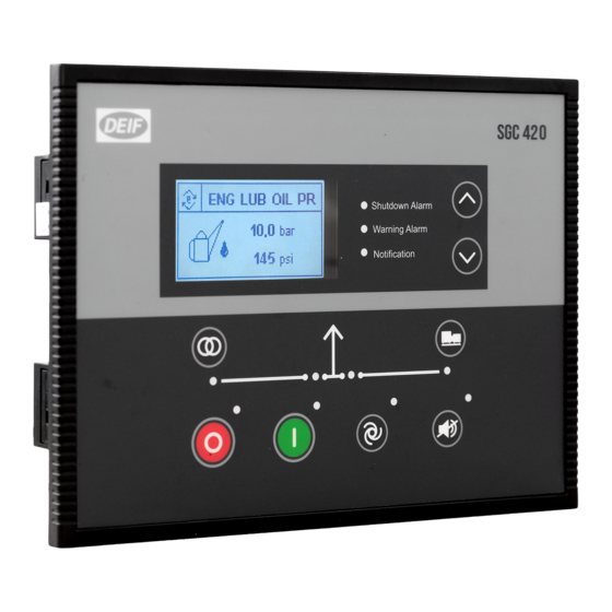
Page 6: Overview Of Controller Buttons
Disclaimer DEIF takes no responsibility for installation or operation of the generator set. If there is any doubt about how to install or operate the engine/generator controlled by the SGC controller, the company responsible for the installation or the operation of the set must be contacted. -
Page 7: Safety Instructions
2. Safety instructions 2.1 General safety instructions This document includes important instructions that should be followed during installation and maintenance of the controller. Installation and maintenance must only be carried out by authorised personnel, and always in accordance with all applicable state and local electrical codes. -
Page 8: Technical Specifications
3. Technical specifications 3.1 Terminals The SGC 420/421 use two types of terminal blocks: Connectors of 5.08 mm pitch Connectors of 10.16 mm pitch Table 3.1 Terminals Connector type Pitch Male (on controller) Female (mating part) Quantity 3-pin 5.08 mm... -
Page 9: Genset Voltage And Frequency Measurements
3.3 Genset voltage and frequency measurements Category Specifications 54 (Neutral) 55 (L3) Controller terminals 56 (L2) 57 (L1) Measurement type True RMS Phase-to-neutral voltage 32 to 300 V AC RMS Phase-to-phase voltage 32 to 520 V AC RMS ±1 % of full scale for phase-to-neutral Voltage accuracy ±1.5 % of full scale for phase-to-phase 1 V AC RMS for phase-to-neutral... -
Page 10: Mains Voltage And Frequency Measurement
3.6 Mains voltage and frequency measurement Category Specifications 50 (Neutral) 51 (L3) Controller terminals 52 (L2) 53 (L1) Measurement type True RMS Phase-to-neutral voltage 32 to 300 V AC RMS Phase-to-phase voltage 32 to 520 V AC RMS ±2 % of full scale for phase-to-neutral Voltage accuracy ±2.5 % of full scale for phase-to-phase 1 V AC RMS for phase-to-neutral... -
Page 11: Analogue Inputs Used As Digital Inputs
SCP connection SCP connections for Analogue inputs 1 to 4*: Terminal 2 Sensor Analogue input Supply resistive Terminal 1 sensor T erminal 16 Sensor common SGC 4xx series Engine body Battery *SCP connections for Analogue input 2 used as Fuel level sensor with the reference configured as Battery Negative Terminal 2 Sensor Analogue... -
Page 12: Analogue Voltage/Current Input
3.10 Analogue voltage/current input Category SGC 421 specifications 21 (Aux3) Controller terminal 23 (Aux4) Measurement type Analogue voltage/current sensing 0 to 5 V DC Range 4 to 20 mA Accuracy ±1.25 % of full scale For genset paralleling application, configure input Aux4 on terminal 23 to accept a 0 to 5 V DC speed bias signal generated by a LSM (Load Sharing Module). -
Page 13: Digital Outputs
3.13 Digital outputs Category Specifications Controller terminals 3, 4, 5, 6, 7, 8, 9 Number of outputs Type DC outputs 5 A (3 and 4) Maximum current rating 1 A (5, 6, 7, 8, 9) Start relay, Fuel relay, Close genset contactor, close mains contactor, Stop Software configurable options solenoid and many more (see Controller overview, Configurable parameters in the User manual for more details). -
Page 14: Sensor Common Point
SCP terminal, and that predictable and accurate analogue sensor measurements are always available in a wide variety of field conditions. 3.17 Communication ports Category Specifications USB 2.0 type B for connection to PC with DEIF Smart Connect software Half Duplex Max. Baud Rate 115200 Data connection 2-wire RS-485 Serial Port Termination resistor of 120 Ω... -
Page 15: Installation
4. Installation 4.1 Dimensions 38.5 233.0 (9.17) (1.52) Shutdown Alarm Warning Alarm Notification Dimensions Length: 233.0 mm (9.17 in) Dimensions Height: 173.0 mm (6.81 in) Depth: 38.5 mm (1.52 in) Length: 219.0 mm (8.62 in) Panel cut-out Height: 158.0 mm (6.22 in) Tolerance: ±... -
Page 16: Terminal Details
4.3 Terminal details Rear view of the controller with terminal details. Terminal Text Description Connector Power ground BATT + Power supply positive DIG OUT A DC output - A DIG OUT B DC output - B DIG OUT C DC output - C BCP-508-10GN DIG OUT D DC output - D... - Page 17 Terminal Text Description Connector GOV_ACT – OUT1 Output for actuator (SGC 421 only) GOV_ACT – OUT2 Output for actuator (SGC 421 only) BCP-508-4GN GOV_ACT – OUT3 Output for actuator (SGC 421 only) GOV_ACT – OUT4 Output for actuator (SGC 421 only) Analogue input auxiliary/0-5 V/4-20 mA (LOP)/ ANLG AUX 3/DIG 0 Digital Input O...
-
Page 18: Typical Wiring Diagrams
CAN High BCP-508-4GN Reserved Reserved 4.4 Typical wiring diagrams Figure 4.1 SGC 420 typical wiring ‐ 42 45 44 47 46 49 54 55 56 57 33 34 35 36 37 38 39 40 41 50 51 52 53 AC voltage... - Page 19 Figure 4.2 SGC 421 typical wiring ‐ 42 45 44 47 46 49 54 55 56 57 33 34 35 36 37 38 39 40 41 50 51 52 53 AC voltage AC voltage AC current CT Digital inputs (configurable) genset Mains Supply...
-
Page 20: Monitoring Mode
5. Monitoring mode 5.1 Monitoring mode In Monitoring mode, the display views shift automatically after a pre-defined time. This delay time can be configured in the configuration menu. The views can also be changed manually with the Up and Down buttons. - Page 21 Engine temperature Shelter temperature Engine speed Engine run time Site run time Auxiliary sensor Histogram Engine/Site battery voltage Alarm (example) USER MANUAL 4189341227A UK Page 21 of 86...
-
Page 22: Configuration Mode
The tables give an overview of configurable parameters. Level 1 (table titles) and Level 2 texts are shown twice: • DEIF Smart Connect software: Normal sentence case, for example Power on Mode. • Controller display: Capital case in brackets, for example (POWER ON MODE) -
Page 23: Module
6.2.2 Module Table 6.1 General (GENERAL) Level 2 Range Profile name Profile 1 Power on Mode Manual (POWER ON MODE) Auto Power on Lamp Test Enable (POWER ON LAMP TEST) Disable Deep Sleep Mode Enable (DEEP SLEEP MODE) Disable Load Histogram Enable (LOAD HISTOGRAM) Disable... - Page 24 Level 2 Range (BATTERY MON) Disable Low Voltage Threshold 12.0 to 60.0 V (LOW BATT THRESHOLD) Battery Monitoring Delay 5 to 300 s (LOW BATT MON DELAY) Genset Run Duration 1 to 720 min. (GEN RUN DURATION) Table 6.5 Cyclic Mode (CYCLIC CONFIG) Level 2 Range Cyclic Mode...
-
Page 25: Digital Inputs
Level 2 Range Duration 00 hr 01 min. to 99 hr 59 min. (GEN ON DURATION) Load Transfer Enable (LOAD TRANSFER) Disable Table 6.8 Night Mode (NIGHT MODE) Level 2 Range Night Mode Enable (NIGHT MODE RESTRICT) Disable Night Mode Start Time 00:00 to 23:59 hour (START TIME) Night Mode Off Duration... - Page 26 Level 2 Range (Digital) Polarity Close to Activate ((DIG) POLARITY) Open to Activate None Notification (Digital) Action Warning ((DIG) ACTION) Electrical Trip Shutdown Never (Digital) Activation From Engine Start ((DIG) ACTIVATION) From Monitoring On Always (Digital) Activation Delay 1 to 180 s ((DIG) ACTIVATION DELAY) None Notification...
- Page 27 Level 2 Range (FLS) Notification Threshold 2 to 80 % (NOTIFICATION THRESHOLD) (FLS) Fuel Tank Capacity 2 to 1000 litre (FUEL TANK SIZE) (FLS) Fuel Theft Warning Enable (FUEL THEFT ALARM) Disable (FLS) Fuel Theft Alarm Threshold 1 to 100 % per hour (FUEL LVL THRESH) None Notification...
- Page 28 Table 6.13 S1 Sensor (AUX S1 RES / DIG M) Level 2 Range Not used Use Input As Digital Input M (SENSOR SELECTION) S1 Sensor Shelter Temperature Sensor (Digital) Source See Digital input source selection in this document ((DIG) SOURCE) Name Auxiliary Input M (NAME)
- Page 29 Table 6.14 S2 Sensor (AUX S2 RES / DIG N) Level 2 Range Not used Use Input As Digital Input N (SENSOR SELECTION) S2 Sensor (Digital) Source See Digital input source selection in this document ((DIG) SOURCE) Name Auxiliary Input N (NAME) (Digital) Polarity Close to Activate...
- Page 30 Level 2 Range (NAME) (Digital) Polarity Close to Activate ((DIG) POLARITY) Open to Activate None Notification (Digital) Action Warning ((DIG) ACTION) Electrical Trip Shutdown Never (Digital) Activation From Engine Start ((DIG) ACTIVATION) From Monitoring On Always (Digital) Activation Delay 1 to 180 s ((DIG) ACTIVATION DELAY) (4-20 mA) Shutdown Enable...
- Page 31 Table 6.16 S4 Sensor (AUX S4 CURR / DIG P) Level 2 Range Not used Use Input As Digital Input P (SENSOR SELECTION) 4 to 20 mA Sensor 0 to 5 V Sensor (Digital) Source See Digital input source selection in this document ((DIG) SOURCE) Name Auxiliary Input P...
-
Page 32: Outputs
Level 2 Range Warning Electrical Trip Shutdown Voltage: 0 to 5 V (0-5 V) Calibration Table Value: 0 to 1000 6.2.5 Outputs Table 6.17 Outputs # (OUT #) Level 2 Range Source See Digital output source selection in this document (SOURCE) On Activation Energise... -
Page 33: Generator
Level 2 Range (ADDN STOPPING TIME) Load Transfer Delay 1 to 60 s (LOAD TRANSFER DELAY) Table 6.20 General (GENERAL TIMER) Level 2 Range Power Save Mode Delay 5 to 1800 s (PWR SAVE MODE DELAY) Screen Changeover Time 1 to 1800 s (SCRN CHNGOVER TIME) Deep Sleep Mode Delay 5 to 1800 s... - Page 34 Table 6.22 Voltage Monitoring (VOLT MONITOR) Level 2 Range Under-voltage Shutdown Enable (UNDER VOLT SHUTDOWN) Disable Under-voltage Shutdown Threshold 50 to 295 V phase-neutral (UV SHUTDOWN THRESH) Under-voltage Warning Enable (UNDER VOLT WARNING) Disable Under-voltage Warning Threshold 55 to 300 V phase-neutral (UV WARNING THRESHOLD) Over-voltage Shutdown Enable...
- Page 35 Level 2 Range Over-current Threshold 5 to 10000 A (OVER CURR THRESHOLD) Over-current Delay 1 to 600 s (OVER CURR DELAY) CT Correction Factor 0.900 to 1.100 CT Location On Alt Output Cable (CT LOCATION) On Load Cable Table 6.25 Earth Leakage/Fan Current Monitoring (EARTH CURR MON) Level 2 Range...
-
Page 36: Mains
Level 2 Range Notification Unbalanced Load Threshold 5 to 200 % (UNBAL LOAD THRESHOLD) Unbalanced Load Delay 1 to 600 s (UNBAL LOAD DELAY) 6.2.8 Mains Table 6.27 Configuration (MAINS CONFIG) Level 2 Range Mains Monitoring Enable (MAINS MONITORING) Disable Mains AC System 1 phase (MAINS AC SYSTEM) -
Page 37: Engine
Level 2 Range (OF ENABLE) Disable (OF) Return 25.0 to 74.0 Hz (OF RETURN) (OF) Trip 26.0 to 75.0 Hz (OF TRIP) 6.2.9 Engine Table 6.30 Crank Disconnect (CRANK DISCONN) Level 2 Range Start Attempts 1 to 9 (START ATTEMPTS) Disconnect on Oil Pressure Sensor Enable (DISCONN ON LOP SENS) - Page 38 Level 2 Range Over-speed Threshold 700 to 4000 RPM (OVER SPEED THRESH) Over-speed Delay 1 to 20 s (OVER SPEED DELAY) Gross Over-speed Threshold 100 to 200 % (GROSS OS THRESHOLD) Table 6.32 Battery Monitoring (BATTERY MONITOR) Level 2 Range None Notification Low Battery Voltage Action...
- Page 39 Level 2 Range (ENG TEMP LIMIT) Table 6.35 Engine Control Unit (ECU) Level 2 Range None Generic J1939 Scania Volvo Engine Type Iveco Deutz - EMR Cummins Measurements from the ECU Enable Lube Oil Pressure Disable Enable Coolant Temperature Disable Enable Engine Speed Disable...
-
Page 40: Maintenance
Level 2 Range None Notification Action Warning Electrical Trip Shutdown Never From Enigine Start Activation From Monitoring On Always Activation Delay 0 to 60 s Table 6.36 Lube Oil Pressure (LOP) Level 2 Range Enable Low Level Shutdown Disable Shutdown Threshold 0.0 to 9.8 Bar Enable Low Level Warning... -
Page 41: Rotary Actuator (Sgc 421 Only)
Level 1 Level 2 Range Letters: A to Z (PASSWORD 1) #### Numbers: 0 to 9 (PASSWORD 2) #### Numbers: 0 to 9 6.2.12 Rotary actuator (SGC 421 only) Table 6.40 General (GENERAL) Level 2 Range Actuator Application As E-Governor (ACTUATOR APPLN) As Start/Stop Device Actuator Speed... -
Page 42: Digital Input Source Selection
Level 2 Range Derivative Gain (Kd) 0 to 1000 (DERIVATIVE GAIN) Friction Setoff 0 to 1000 (FRICTION SETOFF) Gain Schedule Trigger 0.0 to 100.0 % (GAIN SCHEDULE TRIGGER) Loading Factor 0 to 1000 (LOADING FACTOR) Unloading Factor 0 to 1000 (UNLOADING FACTOR) Table 6.43 Engine EGov Config (ENG EGOV CNFG) -
Page 43: Digital Output Source Selection
Input source (on the display) Emergency Stop Remote Start/Stop Simulate Start Simulate Stop Simulate Auto Close Gen/Opn Mains Swch Close Mains/Opn Gen Swch Simulate Mains V-Belt Broken Switch Mains Contactor Latched Genset Contactor Latched Battery Charger Fail Smoke Fire Remote Alarm Mute Remote Alarm Acknowledge Stop and Panel Lock External Panel Lock... - Page 44 Output source Dig In D Dig In E Dig In F Dig In G Dig In H Dig In I Dig In J (LOP Resistive) Dig In K (Anlg In Fuel LVL) Dig In L (Anlg In Eng Temp) Dig In M (Aux Sensor 1) Dig In N (Aux Sensor 2) Dig In O (Aux Sensor 3) Dig In P (Aux Sensor 4)
- Page 45 Output source Under Freq Shutdown Under Speed Shutdown Maintenance Due Stop Mode Auto Mode Manual Mode Preheat Output Calling For Scheduler Run Stop and Panel Lock External Auto Panel Lock Fail To Close Generator Fail To Close Mains Loading Volt Not Reached Loading Freq Not Reached MPU Loss BTS Battery hybrid mode...
-
Page 46: Running Modes
7. Running modes 7.1 Auto mode Select Auto mode with the Mode selection button. Site Battery Monitoring mode DG OFF Mains Mains healthy unhealthy BTS healthy BTS Battery and Shelter temp backup not high BTS Battery unhealthy or Shelter temp high Warm up Warm up delay expired... - Page 47 occurs only when all the three phases fail. Upon Mains failure the genset only receives a Start command if one of following conditions occur: • Site battery voltage level is below its lower limits. • Shelter temperature is above its upper threshold limits. •...
- Page 48 Cyclic mode DG OFF Mains unhealthy/OFF time expired Warm up Warm up delay expired Engine cooling DG ON time expired Mains healthy/ON time expired Return to Mains Return to mains delay expired Engine cooling Cyclic mode is used to run the genset for a pre-specified time for a maximum cycle of 12 hours. The genset running time is configurable.
- Page 49 Do not enable Mains monitoring and Remote start/stop configuration simultaneously. Exercise Mode Two scheduled sequences to start and stop the genset can be configured with SGC 420/421. Exercise mode occurs when the controller is in Auto mode with no shutdown or warning alarms. In this mode, load transfer on mains/genset is configurable.
-
Page 50: Manual Mode
Deep sleep mode Deep sleep mode is a useful feature to extend the battery lifetime. This is done by suspending normal functions of the controller, and place the it in the lowest power consumption state. The controller maintains the status and alarms it had before Deep sleep mode. When the controller wakes up, normal operations are resumed automatically. - Page 51 Start the engine • Press the Stop/Config button. • Press the Start button to crank the engine Shutdown Alarm Warning Alarm If the Start button is pressed in this mode, the Notification controller sends a Start command and the genset starts according to the Start sequence.
-
Page 52: Start And Stop Sequences
Acknowledge and clear alarms • Press the Acknowledge button to acknowledge the alarm in any mode. Shutdown Alarm Warning Alarm Notification NOTE If Engine ON is detected without any start command is given to the controller, the engine will remain ON. Other actions will be according to operating mode and configuration. - Page 53 Stop sequence When the controller receives the Stop command, it goes to the Start Stop state, starts the Stop action time and activates the Stop solenoid output. If Engine OFF is detected before the Stop action time is over, the controller overrides the Stop action time. Stop When the Additional stopping time is over, the controller goes to command...
-
Page 54: Load Detection
8. Load detection 8.1 Load detection in Auto mode The controller detects the load (on mains/genset) from the contactor outputs, for example Close genset contactor and Close mains contactor or Open mains contactor and Open genset contactor. These outputs must be configured in accordance with different types of Auto operating modes and configuration. -
Page 55: Features
9. Features 9.1 About Features The controller includes features to save power and monitor the genset load. 9.2 Auto config exit mode In this mode, the controller automatically exits the Configuration mode when there is no user interaction for the preset Auto config exit mode delay time. -
Page 56: Alarms
10. Alarms 10.1 Alarms When a Shutdown alarm occurs the controller commands the genset to stop. The controller does not send the start command if the Shutdown alarm is not acknowledged. When an Electrical trip alarm occurs, the controller opens the genset contactor and then commands the genset to stop. The controller does not send the start command if the Electrical trip alarm is not acknowledged. - Page 57 Alarms Causes/Indication Actions None Shutdown Eng Temp - Ckt Opn The temperature sensor is not detected (open circuit). Warning Electrical Trip Notification Indicates that the amount of fuel level is below the preset None Low Fuel level (Sensor) threshold. This condition is detected only when engine is Shutdown Warning None...
- Page 58 Alarms Causes/Indication Actions Indicates that genset (L3) phase voltage has fallen below Shutdown L3 Phase Under Voltage the preset under-voltage threshold. Warning None Shutdown DG Phase Reversed Alternator phase sequence (L1-L2-L3) is not correct. Warning Electrical Trip Notification None Mains Phase Reversed Mains is in unhealthy condition.
- Page 59 Alarms Causes/Indication Actions Indicates that engine running hours has exceeded the Warning Maintenance Due preset hours limit or maintenance due date has occurred Notification and filter servicing is required. None Shutdown Battery Charger Fail Indicates the battery is not getting charged by the charger. Warning Electrical Trip Notification...
-
Page 60: Modbus Communication Protocol
11. Modbus communication protocol 11.1 About the Modbus communication protocol SGC 420 supports a custom protocol based on the standard Modbus over an RS-485 layer. operates in a slave mode and responds to commands received from an external Modbus master. -
Page 61: Modbus Communication Settings
12. Modbus communication settings 12.1 Modbus communication settings RS-485 communication settings • Slave ID: 1 to 247 • Baud rate: 1200/2400/4800/9600/19200/38400/57600/115200 bps • Parity: None/Even/Odd • Stop bit: 1, 2 • Recommended polling frequency: 50 Hz • No response timeout: 250 ms 12.2 Register map (function code 03) Register Unit/... - Page 62 Register Unit/ Parameter Scale factor Bits/Sign address Interpretation Load L2 watts Unsigned Load L3 watts Unsigned Load total watts Unsigned Percentage Load Unsigned Load L1 VA Unsigned Load L2 VA Unsigned Load L3 VA Unsigned Load total VA Unsigned Load L1 var kvar Unsigned Load L2 var...
- Page 63 Alarm status Register Unit/ Parameter Scale Factor Bits/Sign address Interpretation Alarm 1 Low oil pressure 13/16-16/16 High coolant temperature 9/16-12/16 Radiator water level/Low fuel level 5/16-8/16 Reserved/Radiator water level switch 1/16-4/16 Alarm 2 Underspeed 13/16-16/16 Overspeed 9/16-12/16 Fail to start 5/16-8/16 Fail to stop 1/16-4/16...
- Page 64 Register Unit/ Parameter Scale Factor Bits/Sign address Interpretation Alarm 8 Auxiliary input A 13/16-16/16 Auxiliary input B 9/16-12/16 Auxiliary input C 5/16-8/16 Auxiliary input D 1/16-4/16 Alarm 9 Auxiliary input E 13/16-16/16 Auxiliary input F 9/16-12/16 Auxiliary input G 5/16-8/16 Auxiliary input H 1/16-4/16 Alarm 10...
- Page 65 Register Unit/ Parameter Scale Factor Bits/Sign address Interpretation Alarm 15 Auxiliary Input S4 13/16-16/16 Auxiliary Input S3 9/16-12/16 Auxiliary Input S2 5/16-8/16 Auxiliary Input S1 1/16-4/16 Alarm 16 Auxiliary S4 open ckt alarm 13/16-16/16 Auxiliary S3 open ckt alarm 9/16-12/16 Auxiliary S2 open ckt alarm 5/16-8/16 Auxiliary S1 open ckt alarm...
- Page 66 Register Unit/ Parameter Scale Factor Bits/Sign address Interpretation Output Diagnostics Digital output A 16/16 Digital output B 15/16 Digital output C 14/16 Digital output D 13/16 Digital output E 12/16 Digital output F 11/16 Digital output G 10/16 Unimplemented 9/16 Unimplemented 8/16 Unimplemented...
- Page 67 Register Unit/ Parameter Scale Factor Bits/Sign address Interpretation DG status Config GCU Mode 16/16 True (1) Mains healthy/Unhealthy 15/16 False (0) Scheduler Cyclic DG operation mode 14-12/16 Auto Manual True (1) Load on DG 11/16 False (0) True (1) Load on Mains 10/16 False (0) Running...
-
Page 68: Register Map (Function Code 16)
Register address Time Hexadecimal Decimal Month Month = 0x04 0x0402 Day = 0x02 Year 2020 The time stamp is 14:18.21, Thursday, 02/04-2020. 12.3 Register map (function code 16) Register map (function code 16) Register Description Note Bits/Sign offset SGC STOP KEY (0x01) SGC START KEY (0x02) DG mode change command Unsigned... -
Page 69: Engine Communication
See the ECU user manuals for the ECU protocol technical description and details of each communication value. Other engines and controllers For engines and controllers not listed in this document, contact DEIF. 13.2 Default settings The SGC controller is delivered with a set of default settings for engine communication. These settings are not necessarily correct for the specific engine/generator set. -
Page 70: Engine Communication Settings
Use the DEIF Smart Connect software to configure engine communication in the SGC controller. Open DEIF Smart Connect and connect to the SGC controller, then select Start > Engine > Engine Control unit (ECU) for the engine communication settings window. -
Page 71: Generic J1939
13.6 Generic J1939 Basic information • Engine controller/type: Any controller which uses generic J1939. • DEIF Smart Connect: Select Generic J1939. • Complies with the J1939 standard. • Baud rate: 250 kb/s Warnings and shutdowns These standard warnings and shutdowns are supported: •... -
Page 72: Wiring
TSC1 SA Torque Speed Control Torque Speed Control 1 (TSC1) is the speed control signal from the SGC to the ECU. For known protocols, the SGC uses the expected source address when TSC1 SA is -1 (default value). You can configure the controller for a specific source address (the range is 0 to 255). -
Page 73: Can Communication
14.1 About the CAN communication protocol SGC 420/421 support a CAN based protocol, which is used to read measurement values, status of alarms and derived calculations (such as cumulative power), as well as to send mode change and start/stop commands to the controller. - Page 74 Communication structure, page 4 Register offset Value Scale factor Unit Bits/Sign Mains L1-N voltage Unsigned Generator power factor L3 Unsigned Generator average power factor Unsigned Communication structure, page 5 Register offset Value Scale factor Unit Bits/Sign Mains L1-L2 voltage Unsigned Mains L2-N voltage Unsigned Mains L3-N voltage...
- Page 75 Communication structure, page 11 Register offset Value Scale factor Unit Bits/Sign Load L1 VAR kvar Unsigned Load L3 VA Unsigned Load total VA Unsigned Communication structure, page 12 Register offset Value Scale factor Unit Bits/Sign Load L2 VAR kvar Unsigned Load L3 VAR kvar Unsigned...
- Page 76 Communication structure, page 20 Register offset Value Scale factor Unit Bits/Sign Charge alternator voltage Unsigned Battery voltage Unsigned Engine speed Unsigned Communication structure, page 21 Register offset Value Scale factor Unit Bits/Sign No of starts Unsigned No of trips Unsigned Eng run hrs Unsigned Communication structure, page 22...
- Page 77 Register offset Value Scale factor Unit Bits/Sign Alarm 3 Reserved 1111 13/16-16/16 Reserved 1111 9/16-12/16 E-0001/0001 Generator low frequency W-0010/0010 5/16-8/16 S-0011/0011 E-0001/0001 Generator high W-0010/0010 1/16-4/16 S-0011/0011 Communication structure, page 24 Register offset Value Scale factor Unit Bits/Sign Alarm 4 E-0001/0001 N-0101/0101 Generator high current...
- Page 78 Register offset Value Scale factor Unit Bits/Sign Alarm 6 E-0001/0001 N-0101/0101 Battery low voltage W-0010/0010 13/16-16/16 E-0100/0100 S-0011/0011 E-0001/0001 N-0101/0101 Battery high voltage W-0010/0010 9/16-12/16 E-0100/0100 S-0011/0011 E-0001/0001 N-0101/0101 Temperature circuit open W-0010/0010 5/16-8/16 E-0100/0100 S-0011/0011 Reserved 1111 1/16-4/16 Communication structure, page 25 Register offset Value Scale factor...
- Page 79 Register offset Value Scale factor Unit Bits/Sign Alarm 8 E-0001/0001 N-0101/0101 Auxiliary input A W-0010/0010 13/16-16/16 E-0100/0100 S-0011/0011 E-0001/0001 N-0101/0101 Auxiliary input B W-0010/0010 9/16-12/16 E-0100/0100 S-0011/0011 E-0001/0001 N-0101/0101 Auxiliary input C W-0010/0010 5/16-8/16 E-0100/0100 S-0011/0011 E-0001/0001 N-0101/0101 Auxiliary input D W-0010/0010 1/16-4/16 E-0100/0100...
- Page 80 Communication structure, page 26 Register offset Value Scale factor Unit Bits/Sign Alarm 10 E-0001/0001 Gen L1 phase low volt W-0010/0010 13/16-16/16 S-0011/0011 E-0001/0001 Gen L1 phase high volt W-0010/0010 9/16-12/16 S-0011/0011 E-0001/0001 Gen L2 phase low volt W-0010/0010 5/16-8/16 S-0011/0011 E-0001/0001 Gen L2 phase high volt W-0010/0010...
- Page 81 Communication structure, page 27 Register offset Value Scale factor Unit Bits/Sign Input/output diagnostics Digital input A 16/16 Digital input B 15/16 Digital input C 14/16 Digital input D 13/16 Digital input E 12/16 Digital input F 11/16 Digital input G 10/16 Digital input H 9/16...
- Page 82 Register offset Value Scale factor Unit Bits/Sign DG status Config (1) Controller mode 16/16 Run (0) True (1) Mains healthy/unhealthy 15/16 False (0) Scheduler-110 Cyclic-111 DG operation mode 14-12/16 Auto-101 Manual-100 True (1) Load on Mains 11/16 False (0) True (1) Load on DG 10/16 False (0)
-
Page 83: Can Packet Structure
Structure of command message Byte no. Byte contents Command ID Command parameters Reserved Reserved Reserved Reserved Reserved Reserved 14.3 CAN packet structure Structure of command message received over CAN: Command ID Description Command parameter (each of 1 Bytes) Bits/ Sign 0x01 - Start DG Start/Stop 0x02 - Stop DG... -
Page 84: Troubleshooting
15. Troubleshooting 15.1 Troubleshooting This section explains the common faults, their possible causes and remedial actions. Table 15.1 General troubleshooting Fault Action • Check the battery voltage. • Check the fuse on the battery supply. The controller does not power ON. •... - Page 85 Fault Action • Enter the Configuration mode in the controller and verify the configuration for Start mode and the Start relay output polarity. • Check the alternator voltage signal (L1 phase) is received by the controller terminal. The engine runs, but the controller shows genset to be OFF.
- Page 86 Table 15.4 Site monitoring troubleshooting Fault Action • Check if panel and Site are properly earthed. Site voltage is observed continuously • Check if the connections are done properly for the differential input (terminals 24 varying. and 25). USER MANUAL 4189341227A UK Page 86 of 86...
Need help?
Do you have a question about the SGC 420 and is the answer not in the manual?
Questions and answers