Table of Contents
Advertisement
Quick Links
Advertisement
Table of Contents

Related Manuals for Deif SGC 120


Summary of Contents for Deif SGC 120
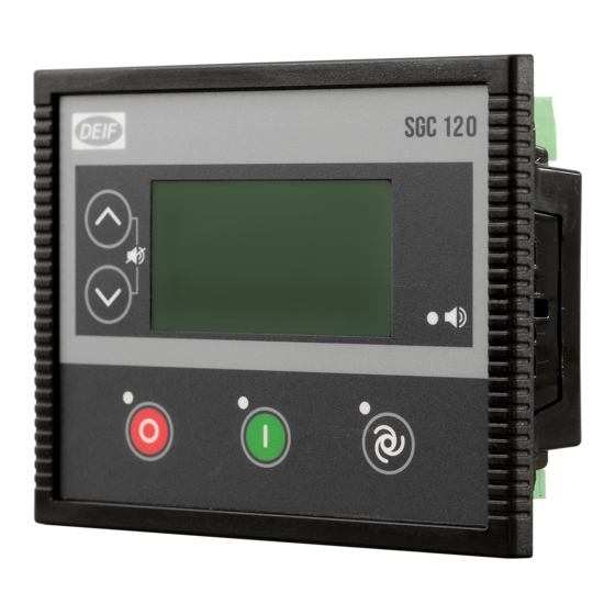
- Page 1 SGC 120 Single Genset Controller User manual...
-
Page 2: Table Of Contents
1. Introduction 1.1 About ................................................... 1.2 Function overview ............................................1.3 About the User manual ........................................... 1.3.1 General purpose ..........................................1.3.2 Software versions ..........................................1.4 Warnings and safety ..........................................1.4.1 Symbols for hazard statements ....................................1.4.2 Symbols for general notes ......................................1.4.3 Electrical safety .......................................... - Page 3 4. Modes of operation 4.1 Operation mode ............................................4.2 AUTO mode ..............................................4.2.1 Island ..............................................4.2.2 Engine drive ............................................4.2.3 Automatic mains failure (AMF) ....................................4.2.4 Remote start/stop ........................................4.2.5 Auto exercise ............................................ 4.3 Manual mode ............................................. 5. General functions 5.1 AC measurement systems .........................................
- Page 4 9. Inputs and outputs 9.1 Digital inputs ............................................... 9.2 Digital outputs ............................................10. Troubleshooting User manual 4189341340A EN Page 4 of 76...
-
Page 5: Introduction
About The SGC 120 controller contains all the functions needed to protect and control the genset, the genset breaker, and also a mains breaker. The values and alarms are shown on the LCD display screen, and operators can control the system from the display. -
Page 6: About The User Manual
About the User manual 1.3.1 General purpose This document includes important instructions that should be followed during installation and maintenance of the controller. Only approved personnel can do the installation and maintenance work. The work must comply with all applicable state and local electrical codes. -
Page 7: Safety During Installation And Operation
DEIF A/S reserves the right to change any of the contents of this document without prior notice. The English version of this document always contains the most recent and up-to-date information about the product. DEIF does not take responsibility for the accuracy of translations, and translations might not be updated at the same time as the English document. -
Page 8: Installation
2. Installation Dimensions Length Height Depth Controller 139.0 mm (5.47 in) 114.0 mm (4.49 in) 38.3 mm (1.51 in) Tolerance: ± 0.3 mm (0.01 Panel cut-out 118.0 mm (4.65 in) 93.0 mm (3.66 in) Tools and materials Tools required for mounting Tool Used for Personal protection, according to local standards and... -
Page 9: Mounting
Materials required for mounting and wiring Materials Used for Four screw clamps Mounting the controller in the front panel Wires and connectors Wiring third party equipment to the controller terminals Cable ties Securing wiring Mounting The controller is designed for mounting in the front panel. Panel cutout: •... - Page 10 Terminal Text Description Power ground BATT + Power supply positive DIG OUT A DC output - A DIG OUT B DC output - B DIG OUT C DC output - C DIG OUT D DC output - D D+ CHG ALT Input for charging alternator control DIG OUT E DC output - E...
-
Page 11: Wiring
Terminal Text Description CT1 S1 CT input 1 from generator phase L1 SENSOR COMM Sensor common point MPU input Wiring 2.5.1 Typical wiring NOTE The wiring diagram is only an example. Use the wiring diagram for the specific application during installation. Fuses: •... -
Page 12: Wiring Guidelines - Best Practice For Grounding
2.5.2 Wiring guidelines - best practice for grounding It is important to follow these wiring guidelines to get: • Reliable readings from the sensors. • Precise measurement of AC voltage and current. • Best protection from lightning and other earth faults. Example: Typical grounding setup 1. -
Page 13: Analogue Inputs
2.5.3 Analogue inputs Resistive sensor inputs Wiring for the sensor common point (SCP) for analogue inputs 1 to 4 (terminals 23 to 26). Wiring for the sensor common point (SCP) for analogue input 2 (terminal 24) when you use it as Fuel level sensor with reference to Battery Negative. -
Page 14: Ac Connections
Settings: • Polarity: Close to activate • SW state: Not activated • Logic status: Low 2.5.4 AC connections Three-phase application (4 wires) Three-phase application (3 wires) User manual 4189341340A EN Page 14 of 76... - Page 15 Two-phase application L1/L2 (3 wires) Two-phase application L1/L3 (3 wires) Single-phase application (2 wires) User manual 4189341340A EN Page 15 of 76...
-
Page 16: Current Transformer (Ct) Ground
Split phase application L1/L2 (3 wires) Split phase application L1/L3 (3 wires) 2.5.5 Current transformer (CT) ground Use one of these methods for the CT ground (S2) connections: 1. The S2 terminals are not grounded. The controller detects the current accurately. 2. -
Page 17: Display And Menus
3. Display and menus Display, buttons, and LEDs Name Function Move the selector up and down on the screen. Navigation To see the Event log, push the Up button and the down button at the same time and hold. Stops the genset if manual or auto mode is selected. Stop When you push the button in auto mode, the running mode also changes to manual mode. -
Page 18: Display Settings
Display settings 3.2.1 Display To adjust for ambient lighting, configure the display settings. Use the smart connect software to configure the contrast in Module > Display > Contrast. You can also configure the time for when the page on the display changes in Timers > General > Screen Changeover Time. Parameter Range Default... -
Page 19: Configuration Menu
Display view examples Some of the display views are only shown if you have configured the functions. Configuration menu To configure a parameter on the controller, follow these steps: 1. Push and hold the Stop/Config button for a minimum of three seconds. 2. -
Page 20: Configurable Parameters
5. Enter the password: a. Use the Up and Down buttons to change the number. b. Select a number with the Start button. 6. You can now configure the parameter. 7. To leave the configuration menu, push and hold the Stop/Config button. - Page 21 Communication (RS485 COMM) Level 2 Range Default Description Communication Mode None None Select the communication mode. (COMM MODE) Modbus Server ID 1 to 247 Select the server ID for Modbus. (MODBUS SLAVE ID) 1200 2400 4800 Baud rate 9600 Select the baud rate for the serial 9600 bps (BAUDRATE) 19200...
-
Page 22: Digital Inputs
Parameter Range Default Description Start Time 00:00 to 23:59 hour 09:59 hours Configure the start time for the sequences. (START TIME) Duration 00 hr 01 min. to 99 hr Configure for how long the genset operates 10 hours, 10 minutes (GEN ON DURATION) 59 min. - Page 23 Parameter Range Default Description Warning Electrical Trip Shutdown Never (Digital) Activation From Engine Start Configure from when the digital input is From Monitoring On ((DIG) ACTIVATION) From Monitoring On monitored. Always (Digital) Activation If the input is active when the timer expires, the Delay 1 to 60 s controller actives the action for the digital input.
- Page 24 Parameter Range Default Description (SHUTDOWN THRESHOLD) If this parameter is enabled, the controller (FLS) Low Fuel Level Enable shows a notification when the fuel level is less Warning Enabled Disable than the notification set point (NOTIFICATION (WARNING) THRESHOLD). (FLS) Warning Threshold The controller shows a notification when the 2 to 80 %...
- Page 25 Parameter Range Default Description From Monitoring On Always (Digital) Activation If the input is active when the timer expires, the Delay 1 to 60 s controller actives the action for the digital input. ((DIG) ACTIVATION DELAY) None (LOP) Circuit Fault Notification Action Warning...
-
Page 26: Outputs
3.5.4 Outputs Outputs # (OUT #) Parameter Range Default Description See Digital output Source source selection in Select an output source from the list. (SOURCE) this document Select what the status of the output source is On Activation Energise De-energise when it is active. -
Page 27: Generator
Parameter Range Default Description (PWR SAVE MODE DELAY) Screen Changeover Time The display page changes when the timer 1 to 1800 s (SCRN CHNGOVER expires. TIME) Deep Sleep Mode Delay If the controller is not in use, the controller goes 5 to 1800 s 10 s (DEEP SLP MODE... - Page 28 Parameter Range Default Description If this parameter is enabled, the load is Auto Load Transfer automatically transferred to the genset when Enable (AUTO LOAD Enabled the voltage and frequency are more than their Disable TRANSFER) minimum set points and the genset is running. This is only for manual mode.
- Page 29 Parameter Range Default Description (UV SHUTDOWN THRESH) If the voltage is less than the set point for Under-voltage under-voltage shutdown (UV SHUTDOWN Shutdown Delay (UV 0.1 to 100 s 10 s THRESH) when this timer expires, the controller SHUTDOWN DELAY) shuts down the engine.
- Page 30 Parameter Range Default Description If the frequency is less than the set point for Under-frequency under-frequency shutdown (UF SHUTDOWN Shutdown Delay (UF 0.1 to 100 s 10 s THRESH) when this timer expires, the controller SHUTDOWN DELAY) shuts down the engine. Under-frequency If this parameter is enabled, the display shows Warning Enable...
- Page 31 Parameter Range Default Description (OVER CURR THRESHOLD) When the delay timer expires, the action for Over-current Delay 1 to 600 s over-current is activated if the current is more (OVER CURR DELAY) than over-current set point. Configure the location of the CT. You can place CT Location On Alt Output Cable On Alt Output Cable...
-
Page 32: Mains
3.5.7 Mains Configuration (MAINS CONFIG) Parameter Range Default Description Mains Monitoring Enable If this parameter is enabled, the controller Enabled (MAINS MONITORING) Disable monitors the mains voltage and frequency. Mains AC System 1 phase 3-phase Select the phase system for the mains. (MAINS AC SYSTEM) 3 phase Phase Reversal... -
Page 33: Engine
Frequency Monitoring (FREQ MONITOR) Parameter Range Default Description If this parameter is enabled, the controller Under-frequency Enable detects a mains failure when the mains (UF ENABLE) Disable frequency is less than the under-frequency set point (UF trip). (UF) Trip If the mains frequency is less than this set 10.0 to 59.0 Hz 45 Hz (UF TRIP) - Page 34 Parameter Range Default Description Crank Disconnect At If the frequency is more than this set point Alt Frequency 10 to 70 Hz 20 Hz during cranking, the controller disconnects the (ALT FREQUENCY) crank. Crank Disconnect At If the engine speed is more than this set point Engine Speed 150 to 4000 RPM 600 RPM...
- Page 35 Parameter Range Default Description Idle to Rated Delay Time for the engine to go from idle speed to 0 to 1200 s 10 s Time rated speed. The engine operates at low speed for this time Start-up Idle Mode 0 to 1200 s 10 s duration.
- Page 36 Parameter Range Default Description the timer expires, the controller activates the (FAIL DELAY) action for charging alternator failure. Preheating (PREHEAT) Parameter Range Default Description Pre-heat Timer When the pre-heat timer expires, the engine 1 to 900 s 10 s (PREHEAT TIMER) starts to crank.
- Page 37 Engine Control Unit (ECU) Parameter Range Default Description None Conventional Generic J1939 Scania Volvo Iveco Deutz - EMR Engine Type Conventional Select the engine type. KUBOTA Weichai Hatz PERKINS ADEM4 Yuchai YCGCU ECU Cummins Yuchai Bosch Measurements from the ECU Enable Lube Oil Pressure Not enabled...
- Page 38 Parameter Range Default Description If there is a communication failure when the Activation Delay 1 to 60 s delay timer expires, the action for ECU communication failure is activated. Communication Setup SGC Source Address 0 to 253 Source address for the SGC. ECU Source Address 0 to 253 Source address for the ECU.
-
Page 39: Maintenance
Parameter Range Default Description level is less than the warning set point (Warning Threshold). If the lube oil pressure is more than this set Warning Threshold 0.2 to 10.0 Bar 3 Bar point, the controller activates a warning alarm. 3.5.9 Maintenance Maintenance (MAINT ALARM) Parameter Range... - Page 40 PASSWORD 1 Password changed User manual 4189341340A EN Page 40 of 76...
-
Page 41: Modes Of Operation
4. Modes of operation Operation mode The controller has two running modes: • AUTO: The controller operates automatically, and the operator cannot initiate sequences manually. • Manual: The operator has to initiate all sequences. You can do this with the buttons, Modbus commands, or digital inputs. -
Page 42: Engine Drive
4.2.2 Engine drive You can use the SGC to control one engine. The controller has all the necessary functions to control and protect an engine. To use the controller to control an engine drive, go to Generator > Alternator Configuration in the smart connect software. - Page 43 • Mains monitoring is enabled. In the smart connect software, go to Mains > Configuration > Mains monitoring and make sure that mains monitoring is enabled. To make sure that auto exercise is not enabled for events 1 and 2, go to Module > Auto Exercise >...
-
Page 44: Remote Start/Stop
Minimum voltage and frequency set points Generator > Alternator Configuration Parameter Range Default Min Healthy Voltage 10 to 100 % 40 % Min Healthy Frequency 10 to 100 % 40 % 4.2.4 Remote start/stop You can configure digital inputs as remote start/stop inputs (latched type input). You can start and stop the genset remotely by activating the configured remote start/stop inputs. -
Page 45: Auto Exercise
Minimum voltage and frequency set points Generator > Alternator Configuration Parameter Range Default Min Healthy Voltage 10 to 100 % 40 % Min Healthy Frequency 10 to 100 % 40 % Timers Timers > Start/Stop Parameter Range Default Warm-Up Delay 0 to 60 s Load Transfer Delay 1 to 60 s... -
Page 46: Manual Mode
Manual mode When you select manual mode, you can control the controller from the display and with digital inputs. To go to manual mode, push the Mode selection button. User manual 4189341340A EN Page 46 of 76... -
Page 47: General Functions
5. General functions AC measurement systems The AC system can be three-phase, two-phase, single-phase, or split phase. CAUTION Incorrect configuration is dangerous Configure the correct AC configuration. If in doubt, contact the switchboard manufacturer for information. Nominal settings 5.2.1 Default nominal settings Text Range Default... -
Page 48: Breakers
Text Range Default Note Check the minimum and maximum values the SGC Nominal load current 0 to 8000 A 350 A can read and display. Remember to include the Check the minimum and maximum values the SGC Nominal 4th CT current 0 to 8000 A 800 A can read and display. -
Page 49: Load Calculations
Timers > General Parameter Range Default Breaker Close Delay 0.1 to 30 s Load calculations For automatic mains failure (AMF) applications, you can place the current transformer (CT) on the line from the genset or on the load cable. The load calculations are based on where the CT is placed. If the location of the CT is on the On Alt Output cable, which means the CT is on the genset side, then the load calculations are based on the genset load. - Page 50 Alarms and their causes Alarms Causes/Indication Actions The measured oil pressure is less than the configured Shutdown Low Oil Pressure (Sensor) value. Warning Shutdown Warning Low Oil Pressure (Switch) The switch has measured a low oil pressure. Electrical Trip Notification The measured fuel level is less than the configured Shutdown Low Fuel level (Sensor)
- Page 51 Alarms Causes/Indication Actions Emergency stop is activated. Emergency Stop Shutdown The emergency stop is configured as a digital input, and the input has triggered for longer than the configured time. Shutdown The charge alternator voltage is less than the Warning Charge Fail configured value.
- Page 52 Alarms Causes/Indication Actions Shutdown Warning DG Phase Reversal Alternator phase sequence (L1-L2-L3) is not correct. Electrical Trip Notification Mains Phase Reversal Error during mains operation. Notification Shutdown LOP/Ckt Open (terminal The oil pressure sensor on terminal 26 is not detected Warning (circuit open).
- Page 53 Alarms Causes/Indication Actions Shutdown Breaker close failure. Unable to close the genset Warning Fail To Close Gen Output breaker. Electrical Trip Notification Shutdown Fail To Close Mains Breaker close failure. Unable to close the mains Warning Output breaker. Electrical Trip Notification Shutdown Breaker close failure.
-
Page 54: Engine Functions
6. Engine functions Engine sequences The engine start and stop sequences are started automatically if AUTO mode is selected. In manual mode, the operator has to initiate the sequences. Engine start functions 6.2.1 Start sequence The following drawing shows the start sequence of the genset. Configure the run coil timer to activate the fuel relay output and the idle mode output before pre-heat is completed. - Page 55 Timers > General Parameter Range Default Safety Monitoring Delay 10 to 60 s 10 s Warm-Up Delay 0 to 60 s ISV Pull Signal Timer 0.1 s Engine Engine > Preheat Parameter Range Default Preheat Timer 0 to 1200 s 10 s Engine >...
- Page 56 Start sequence flowchart 1. The controller sends a start signal to the genset. 2. The Start Delay timer is activated. 3. When the Start Delay timer expires, the pre-heating function is activated if this is configured. If pre-heating is not configured, go to step 7 (crank hold). 4.
-
Page 57: Engine Stop Functions
Engine stop functions 6.3.1 Stop sequence The stop sequence is activated if a stop command is given. The stop sequence includes the cooling down time if the stop is a normal or controlled stop. Timers > General Parameter Range Default Engine Cooling Time 0 to 300 s Stop Action... -
Page 58: Stop Sequence Flowchart
6.3.2 Stop sequence flowchart 1. The genset breaker opens if there is a breaker in the application. 2. A stop command is given. You can activate the command with a digital input or Modbus. You can only use the display buttons in manual mode. 3. -
Page 59: Idle Mode
Idle mode The purpose of the idle mode function is to allow the engine to operate at idle speed before ramping up to rated speed. You can activate idle mode using a digital input or a timer. If you have configured an input and a timer for idle mode, then the timer is overruled. -
Page 60: Coolant Temperature
Stop sequence for idle mode You can also activate idle mode during the stop sequence. Go to Engine > Speed Monitoring > Stopping Idle Time to configure the timer for the idle stop time. If you set the timer to 0 seconds, idle mode is not activated during the stop sequence. - Page 61 3. Go to the Outputs tab and select the output you want to use. 4. Use the drop-down list next to the output to select Coolant Heater Control Output as the source. 5. Go to the Engine tab and select Coolant Control. 6.
-
Page 62: Engine Pre-Heater
Engine pre-heater This function is used to control the temperature of the engine before the engine starts. The function is only active when the engine is stopped. A temperature sensor is used to activate an external heating system to keep the engine at a minimum temperature. -
Page 63: Other Functions
Parameter Range Default Description for the engine temperature (Engine Coolant Temp Threshold). Engine Coolant Temp The coolant temperature the engine must reach 10 to 300 °C 25 °C Threshold during pre-heat. Other functions 6.7.1 Maintenance timer The controller has one timer to monitor maintenance intervals. The timer function is based on engine running hours or a due date. - Page 64 Engine stop Cooling down Extended stop Keyswitch output User manual 4189341340A EN Page 64 of 76...
-
Page 65: Modbus
For more information about Modbus in general and the Modbus protocol, refer to the documentation freely available at http://www.modbus.org. Refer to the Modbus tables, available for download at www.deif.com, to see how the controller data is mapped to the Modbus addresses. - Page 66 Byte Field Comments Number of registers to write - high byte Number of registers to write must be between 1 to Number of registers to write - low byte Number of data bytes to follow (n) Value at first register Value at last register 7+n/8+n Error check CRC...
-
Page 67: Can Bus Engine Communication
NOTE See the ECU user manuals for the ECU protocol technical description and details of each communication value. Other engines and controllers For engines and controllers not listed in this document, contact DEIF. 8.1.2 Default settings The SGC controller is delivered with a set of default settings for engine communication. These settings are not necessarily correct for your engine or genset. -
Page 68: Engine Values On The Display
Engine communication settings Use the DEIF smart connect software to configure engine communication for the SGC controller. Open DEIF smart connect and connect to the SGC controller. Select Start > Engine > Engine Control unit (ECU) to see the engine communication settings. -
Page 69: Generic J1939
See the specific documentation for the engine/ECU for information about the source address. Generic J1939 Basic information • Engine controller/type: A controller that uses generic J1939. • DEIF smart connect: Select Generic J1939. • Complies with the J1939 standard. • Baud rate: 250 kb/s Warnings and shutdowns These standard warnings and shutdowns are supported: •... - Page 70 • Use the Up and Down buttons to go through the alarm list. • oc##: Shows how many times a specific alarm has occurred. • CLRALL: Push ENTER to clear the entire alarm log list. For safety reasons, this requires the master password. NOTE If the controller has no translation text for an SPN diagnostic number, Text N/A is shown.
- Page 71 9. Inputs and outputs Digital inputs Source Description Not used The digital input is not used. User configured The digital input is configured by the user. The input is activated when the fuel level is less than the configured value. Low fuel level switch The configured alarm is shown.
- Page 72 Source Description • Mains monitoring is enabled and there is a mains failure. The input is deactivated. The is still a mains failure and the mains breaker opens. When this input is activated an alarm is shown on the display. You can V-belt broken switch configure the alarm type.
- Page 73 Output source Description Dig In F This output is activated when digital input F is activated. Dig In G This output is activated when digital input G is activated. Dig In H This output is activated when digital input H is activated. Dig In I This output is activated when digital input I is activated.
- Page 74 Output source Description This output is activated when the shutdown alarm for gross overspeed is Gross over speed shutdown activated. This output is activated when the start relay is activated during the engine Start relay start sequence. This output is activated when the alarm for the temperature sensor (open Temp sensor open circuit circuit) is activated.
- Page 75 10. Troubleshooting General troubleshooting Fault Action • Check the battery voltage. • Check the fuse on the battery supply. The controller does not power ON. • Check continuity between battery positive and controller terminal 2. • Check continuity between battery ground and controller terminal 1. The controller display freezes or hangs •...
- Page 76 Fault Action • Check if the MPU signal (if used), and main alternator voltage signal (L1 phase) are received by the controller terminals. The engine runs, but the controller shows genset to be OFF. • Check if the LOP and LLOP are working OK. Check the wiring to the controller.
Need help?
Do you have a question about the SGC 120 and is the answer not in the manual?
Questions and answers