
Related Manuals for Deif SGC 110


Summary of Contents for Deif SGC 110
- Page 1 User manual Document no.: 4189341228A Single Genset Controller SGC 110 DEIF A/S · Frisenborgvej 33 · DK-7800 Skive · Tel.: +45 9614 9614 · Fax: +45 9614 9615 · info@deif.com · www.deif.com...
-
Page 2: Table Of Contents
1. Introduction 1.1 About SGC 110 ............................................1.2 Key functions ............................................... 1.3 Product overview ............................................1.4 Passwords ..............................................1.5 Overview of controller buttons ......................................1.6 Legal information ............................................2. Safety instructions 2.1 General safety instructions ........................................2.2 Electrical safety ............................................ - Page 3 7.2 Deep sleep mode ............................................. 7.3 Manual mode .............................................. 8. Alarms 8.1 Alarms ................................................9. Troubleshooting 9.1 Troubleshooting ............................................USER MANUAL 4189341228A UK Page 3 of 34...
-
Page 4: Introduction
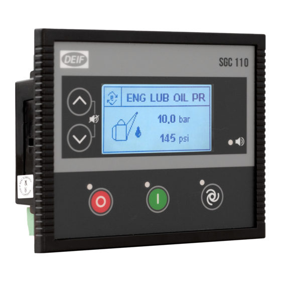
This document presents information necessary for operating DEIF's SGC 110 genset controller. SGC 110 is a modern genset controller with user friendly HMI and full graphics LCD. The controller comes with a highly versatile software. Extensive inputs and outputs support a wide variety of industry standard features in diesel/gasoline genset applications. -
Page 5: Passwords
1.4 Passwords The controller is protected from set-up changes with a four digit password. There are two password levels: Level Access Factory setting Full access (read and write) 0123 Limited access (read) 1234 The passwords can be changed on the controller: 1. -
Page 6: Legal Information
Disclaimer DEIF takes no responsibility for installation or operation of the generator set. If there is any doubt about how to install or operate the engine/generator controlled by the SGC controller, the company responsible for the installation or the operation of the set must be contacted. -
Page 7: Safety Instructions
2. Safety instructions 2.1 General safety instructions This document includes important instructions that should be followed during installation and maintenance of the controller. Installation and maintenance must only be carried out by authorised personnel, and always in accordance with all applicable state and local electrical codes. -
Page 8: Technical_Specifications
3. Technical_specifications 3.1 Terminals The SGC 110 uses two types of terminal blocks: Connectors of 3.5 mm pitch Connectors of 5.08 mm pitch Table 3.1 Terminals Connector type Pitch Male (on controller)* Female (mating part)* Quantity 4-pin 3.5 mm 5441294... -
Page 9: Genset Voltage And Frequency Measurements
3.3 Genset voltage and frequency measurements Category Specifications 27 (Neutral) 28 (L3) Controller terminals 29 (L2) 30 (L1) Measurement type True RMS Phase-to-neutral voltage 32 to 300 V AC RMS Phase-to-phase voltage 32 to 520 V AC RMS Voltage accuracy ±2 % of full scale for phase-to-phase 1 V AC RMS for phase-to-neutral Voltage resolution... -
Page 10: Analogue Inputs Used As Digital Inputs
SCP connection SCP connections for Analogue inputs 1 to 3*: Terminal 2 Sensor Analogue input Supply resistive Terminal 1 sensor T erminal 41 Sensor common SGC 1xx series Engine body Battery *SCP connections for Analogue input 2 used as Fuel level sensor with the reference configured as Battery Negative Terminal 2 Sensor Analogue... -
Page 11: Sensor Common Point
Genset and mains contactor latching relays should be compiled against 4 kVA surge as per IEC-61000-4-5 standard. 3.10 Communication ports Category Specifications USB 2.0 type B for connection to PC with DEIF Smart Connect software. USER MANUAL 4189341228A UK Page 11 of 34... -
Page 12: Installation
4. Installation 4.1 Dimensions 38.3 139.0 (5.47) (1.51) Length Height Depth Controller 139.0 mm (5.47 in) 114.0 mm (4.49 in) 38.3 mm (1.51 in) Panel cut-out 118.0 mm (4.65 in) 93.0 mm (3.66 in) Tolerance: ± 0.3 mm (0.01 in) 4.2 Mounting in panel To mount the controller into the panel, use the fixing clips provided along with the controller. -
Page 13: Terminal Details
4.3 Terminal details Rear view of the controller with terminal details. Terminal Text Description Phoenix connector Power ground 5441980 BATT + Power supply positive DIG OUT A DC output - A DIG OUT B DC output - B 5441223 DIG OUT C DC output - C DIG OUT D DC output - D... - Page 14 Terminal Text Description Phoenix connector GEN_V–IN NTRL Voltage input from Generator Neutral GEN_V–IN L3 Voltage input from Generator phase L3 5453499 GEN_V–IN L2 Voltage input from Generator phase L2 GEN_V–IN L1 Voltage input from Generator phase L1 Reserved Reserved Reserved Reserved Reserved Reserved...
-
Page 15: Typical Wiring Diagram
4.4 Typical wiring diagram Figure 4.1 SGC 110 typical wiring ‐ 27 28 29 30 10 11 12 21 22 AC voltage Digital inputs genset (configurable) Supply Outputs Analogue inputs 25 26 ‐ Engine body NOTE • Fuses: ◦ F1: 5 A ◦... -
Page 16: Monitoring Mode
5. Monitoring mode 5.1 Monitoring mode In Monitoring mode, the display views shift automatically after a pre-defined time. This delay time can be configured in the configuration menu. The views can also be changed manually with the Up and Down buttons. -
Page 17: Configuration Mode
The tables give an overview of configurable parameters. Level 1 (table titles) and Level 2 texts are shown twice: • DEIF Smart Connect software: Normal sentence case, for example Power on Mode. • Controller display: Capital case in brackets, for example (POWER ON MODE) -
Page 18: Module
6.2.2 Module Table 6.1 General (GENERAL) Level 2 Range Profile name Profile 1 Power on Mode Manual (POWER ON MODE) Auto Power on Lamp Test Enable (POWER ON LAMP TEST) Disable Deep Sleep Mode Enable (DEEP SLEEP MODE) Disable Auto-Clear Warning Alarm Enable (AUTO CLEAR WARNINGS) Disable... -
Page 19: Analogue Inputs
6.2.4 Analogue inputs Table 6.4 Analogue Input 1 (ENG TEMP / DIG G) Level 2 Range Not used Use Input As Digital Input G (SENSOR SELECTION) Engine Coolant Temperature Sensor (Digital) Source See Digital input source selection in this document ((DIG) SOURCE) Name Auxiliary Input G... - Page 20 Level 2 Range From Monitoring On Always (Digital) Activation Delay 1 to 60 s ((DIG) ACTIVATION DELAY) (FLS) Low Fuel Level Shutdown Enable (SHUTDOWN) Disable (FLS) Shutdown Threshold 0 to 78 % (SHUTDOWN THRESHOLD) (FLS) Low Fuel Level Notification Enable (NOTIFICATION) Disable (FLS) Notification Threshold...
-
Page 21: Outputs
Level 2 Range (Digital) Activation Delay 1 to 60 s ((DIG) ACTIVATION DELAY) None Notification (LOP) Circuit Fault Action Warning (OPEN CKT ALARM) Electrical Trip Shutdown Resistance: 10 to 100 Ω (LOP) Lube Oil Pressure Sensor Calibration Pressure: 1.0 to 10.0 bar 6.2.5 Outputs Table 6.7 Outputs # (OUT #) -
Page 22: Generator
Level 2 Range Stop Action Time 10 to 120 s (STOP ACTION TIME) Additional Stopping Time 0 to 120 s (ADDN STOPPING TIME) Load Transfer Delay 0 to 60 s (LOAD TRANSFER DELAY) Power Save Mode Delay 5 to 1800 s (PWR SAVE MODE DELAY) Screen Changeover Time 1 to 1800 s... -
Page 23: Engine
Level 2 Range Under-voltage Warning Enable (UNDER VOLT WARNING) Disable Under-voltage Warning Threshold 55 to 300 V phase-neutral (UV WARNING THRESHOLD) Over-voltage Shutdown Enable (OVER VOLT SHUTDOWN) Disable Over-voltage Shutdown Threshold 105 to 350 V phase-neutral (OV SHUTDOWN THRESH) Over-voltage Warning Enable (OVER VOLT WARNING) Disable... - Page 24 Level 2 Range Disconnect on Oil Pressure Switch Enable (DISCONN ON LLOP SW) Disable Pressure Switch Transient Time 0.0 to 3.0 s (LLOP SW TRANS TIME) Crank Disconnect At Alt Frequency 10 to 70 Hz (ALT FREQUENCY) Crank Disconnect At Engine Speed 150 to 4000 RPM (ENGINE SPEED) Disconnect On Charging Alt Voltage...
-
Page 25: Maintenance
Level 2 Range Shutdown High Battery Voltage Threshold 9.0 to 32.0 V (HIGH VOLT THRESHOLD) High Battery Voltage Delay 5 to 1800 s (HIGH VOLT DELAY) Table 6.16 Charging Alternator Monitoring (CHARGE ALT MON) Level 2 Range None Notification Charging Alternator Fail Action Warning (FAIL ACTION) Electrical Trip... -
Page 26: Digital Input Source Selection
6.3 Digital input source selection Input source Not Used User Configured Low Fuel LVL Switch Low Lube Oil Press Switch High Engine Coolant Temp Switch Low Water LVL Switch Emergency Stop Remote Start/Stop Simulate Start Simulate Stop Simulate Auto Close Gen/Open Mains Switch Close Mains/Open Gen Switch Reserved1 V-Belt Broken Switch... - Page 27 Output source Dig In F (Anlg In LOP 1) Dig In G (Analog Eng Temp) Dig In H (Anlg In Fuel LVL) Reserved2 Emergency Stop Stop Solenoid Fail To Start Fail To Stop Fuel Relay Gen Available L1 Phase OV Shutdown L1 Phase UV Shutdown L2 Phase OV Shutdown L2 Phase UV Shutdown...
-
Page 28: Running Modes
7. Running modes 7.1 Remote start/stop mode To use the Remote start/stop mode, configure one of the digital input as Remote start/stop (Latched type input) and set the controllerto Auto mode. To start or stop the genset while in Remote start/stop mode, activate/deactivate (continuous signal) the pre-configured Remote start/ stop input. - Page 29 7.2 Deep sleep mode Deep sleep mode is a useful feature to prolong the battery life. In this mode, normal functions of the controller are suspended and the controller is placed in its lowest power consumption state. The controller maintains the status and alarms it had before Deep sleep mode.
- Page 30 8. Alarms 8.1 Alarms With SGC 110 it is possible to configure several Shutdown/Electrical trip, Warning and Notification alarms, for example Low oil pressure shutdown, Overload warning, and more. An alarm occurs when a pre-configured parameter is out of the preset level. The Alarm LED flashes and the Sounder alarm activates (if configured).
- Page 31 Alarms Causes/Indication Actions Shutdown Indicates that radiator water level is below the preset Warning Low Water Level switch threshold. Electrical Trip Notification Indicates that genset speed has exceeded the preset Over Speed overspeed threshold. The genset will shut down after Shutdown Overspeed delay.
- Page 32 Alarms Causes/Indication Actions Indicates that genset has not started after the preset Fail to Start Shutdown number of Start attempts. Fuel theft The fuel consumption exceeds the preset threshold. Warning Eng Temp/terminal 24 - Ckt The temperature sensor is not detected (circuit open). Warning Fuel Level Ckt Open The fuel level sensor is not detected (circuit open).
- Page 33 9. Troubleshooting 9.1 Troubleshooting This section explains the common faults, their possible causes and remedial actions. General troubleshooting Fault Action • Check the battery voltage. • Check the fuse on the battery supply. The controller does not power ON. • Check continuity between battery positive and controller terminal 2.
- Page 34 Fault Action • Ensure that the controller's output terminal is not directly connected to the starter relay. The controller's output should be given to an intermediate relay which should in-turn power the starter relay. The controller can get permanently damaged and The controller sends a Crank-start will need to be replaced if this precaution is not taken.
Need help?
Do you have a question about the SGC 110 and is the answer not in the manual?
Questions and answers