Bennett 3000 Series Installation & Operator's Manual

Commercial and retail dispensers
Hide thumbs Also See for 3000 Series:

Advertisement

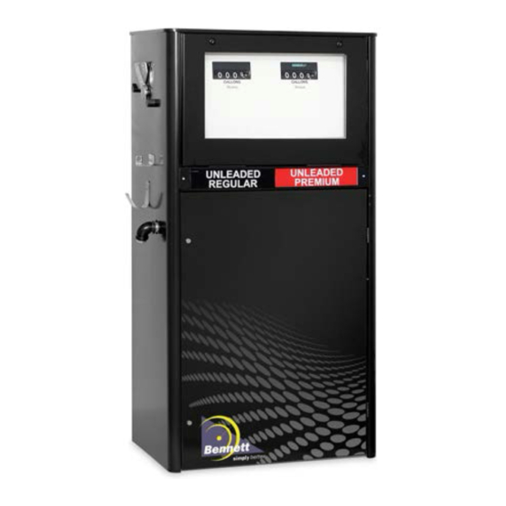
Bennett 3000 Series Mechanical
Commercial and Retail Dispensers
Installation & Operator's Manual
Only Trained Personnel May Work on This Equipment
Includes Instructions For:
Model 3100 Commercial Mechanical 101 (Volume Only)
Non-computer with Electric Reset
Model 3200 Commercial Mechanical, 101 (Volume Only)
Non-Computer & Cam AC Reset
Model 3300 Retail Mechanical (Money & Volume), V/R
10/4 & Electric Reset
Model 3400 Retail Mechanical (Money & Volume),
V/R 10/4 & Cam AC
Model 3500 Retail Mechanical (Money & Volume),
V/R 10 & Electric Reset
Model 3600 Retail Mechanical (Money & Volume),
V/R 10 & Cam AC
Remote Dispensers
and
Self-Contained Pumps
READ THIS MANUAL
This manual has important information for safe installation and
operation of this equipment. Read and understand this manual
before applying power. Keep this manual and tell all service
personnel to read this manual.
instructions, you can cause bodily injury, death or damage to the
equipment.
For new manuals, FAX to:
BENNETT MARKETING SERVICES
(231)799-6202
or visit our web page at:
http://www.bennettpump.com
If you do not follow the
Bennett 1218 E. Pontaluna Road, Spring Lake, MI 49456
USA 800-235-7618 ~ Outside USA 231-798-1310
sales@bennettpump.com ~ www.bennettpump.com
107929 Rev E 04-24-17

Advertisement

Table of Contents
loading

Summary of Contents for Bennett 3000 Series

  • Page 1 For new manuals, FAX to: BENNETT MARKETING SERVICES (231)799-6202 or visit our web page at: http://www.bennettpump.com 107929 Rev E 04-24-17 Bennett 1218 E. Pontaluna Road, Spring Lake, MI 49456 USA 800-235-7618 ~ Outside USA 231-798-1310 sales@bennettpump.com ~ www.bennettpump.com...
  • Page 2: Table Of Contents

    Potting Instructions Base Dimensions and Wiring Diagrams Site Audit Form Bennett Limited Warranty for Products Installed in the United States - 3000 Retail & Commercial Bennett International Limited Warranty for Dispensers and Pumps ............47 NOTICE Not all equipment covered in this manual is listed by Underwriters Laboratories. Only those products that bear the Listing Mark of Underwriters Laboratories are listed.
  • Page 3: Safety Instructions

    Warranty work may only performed Bennett certified CAUTION: Do not drill holes in fuel technicians. dispensers. Holes can cause failure of the electronic equipment. The warranty will become...
  • Page 4: Introduction For The 3000 Series Mechanical Commercial And Retail Dispensers

    380 Volt 3-Phase Motors tive displacement design  Cam-AC manual reset in lieu of electric reset  Type 75 Bennett rotary vane pumping unit with  VR10 Veeder-Root extended price range com- integral vortex air eliminator puter for Heritage 3000 series ...
  • Page 5  Conformance is available upon Companion LPS satellites positive displacement design request  Type 75 or type 75-HD Bennett sliding Specifications in this document vane pumping unit with integral vortex air are subject to change without eliminator notice. 107929 Rev E 04-24-17...
  • Page 6: Product Specifications

    ENVIRONMENTAL REQUIREMENTS Operating Temperature Range: -30° to +50°C Humidity: 0-95% non - condensing DIMENSIONS 3000 Series - Low Hose 60” H X 30” W x 20” D High Hose 88”H x 30”W x 20”D 107929 Rev E 04-24-17...
  • Page 7: Determining The Model Number

    Understanding the features of the dispenser to be installed will be helpful in understanding the proper installation of the dispenser. How a Model for the 3000 Series Dispensers is Made Up. Pump Model...
  • Page 8: Dispenser Identification Number Summary (Din)

    Determining the Model Number 107929 Rev E 04-24-17...
  • Page 9: Unloading, Unpacking And Inspecting A New Dispenser

    Use a fork lift to lift the dispenser from the bottom while it is still on the pallet. Bennett dispensers are shipped from our factory F.O.B. This means that the title to the equipment passes to the purchaser at the time the equipment is loaded on the truck at our factory. Freight damage claims are the responsibility of the purchaser.
  • Page 10: Lifting A New Dispenser And Placing It On The Island

    Lifting a New Dispenser and Placing it on the Island The dispenser is bolted to a pallet with bolts and nuts. With the lower doors removed and safely stored away, remove the nuts and bolts that secure the dispenser to the pallet. Unlock the lower door with the keys that come with the unit.
  • Page 11 Lifting a New Dispenser and Placing it on the Island Alternate Method for High Hose Lifting the Dispenser from Above - On the high hose models, there are lifting brackets provided in the upper area of the dispenser. There is a cover that has to be removed to access these brackets. (See Figures 1 + 2 below).
  • Page 12: Adjustable Nozzle Hook Instructions

    Adjustable Nozzle Hook Instructions For standard interchangeable Use top mounting holes in nozzle nozzles, use bottom mounting holes hook bracket as shown above for the in nozzle hook bracket as shown following nozzles: OPW 7H & 7BH; above. Examples of standard Richards Mark 7 &...
  • Page 13 This page intentionally left blank 107929 Rev E 04-24-17...
  • Page 14: Determining The Number Of Product Supply Pipes Needed

    Determining the Number of Product Supply Pipes Needed Step 1: Determine the type of supply line needed from the model number’s 7th position on the serial tag. If the model number is 3111SNR (Note the R) the dispenser will require a submerged pump and pressurized supply line for each product.
  • Page 15: Mechanical And Plumbing Notes

    Read and follow all instructions on the wiring diagram and observe all national and local electrical codes. In instances where new dispensers are replacing old dispensers, Bennett recommends that new wiring be pulled to each dispenser.
  • Page 16 All underground conduit should be rigid metal and drawn up tight. The use of PVC (plastic) conduit is not allowed and will void the Bennett Warranty. Make sure that vapor “seal offs” are properly installed on all conduits at and from each dispenser.
  • Page 17: Pipelines And Underground Containment Sumps

    The dispenser must be mounted on a concrete foundation. Do not pour concrete around the product pipes or electrical conduit. The use of a UL approved containment sump designed for the Bennett Dispenser Model used is highly recommended. Follow the containment sump manufacture’s installation instructions for proper installation.
  • Page 18: Above Ground Tank Installations

    Above Ground Tank Installation with Self Contained Pumps Bennett self contained dispensers can be used with above ground tank installations if the following requirements are met:  An Underwriters (U.L.) Listed Pressure Regulating Valve designed for under-the-pump mounting is installed for each pumping unit according to the valve manufacturer’s instructions.
  • Page 19: Purging Product Lines For Remote Dispensers

    RUNNING THE METER IN A DRY CONDITION AND AT THE HIGH SPEEDS RESULTING FROM PRESSURIZED AIR, WILL DAMAGE THE METER AND VOID THE BENNETT LIMITED WARRANTY. The emergency shut off valve contains a test port that may be used to bleed off air that may be trapped in the product lines for remote units.
  • Page 20: Piping Notes For Self Contained (Suction) Pumps

    Piping Notes for Self Contained (Suction) Pumps To obtain maximum flow rates on a self-contained pump, follow these guidelines: The total length of horizontal piping between the pump and tank must be no longer than 60 feet. Use new 1-1/2” galvanized or approved non-metallic pipe for 10-15gpm pumps. Use new 2” galvanized or approved non-metallic pipe for 20-24 gpm pumps.
  • Page 21: Dispenser Startup And Checklist

    Dispenser Startup and Checklist DANGER: Fire, explosion, injury or death will occur if fuel vapors are present. Make sure there are no vapors present before starting this procedure. CAUTION: To prevent damage to the dispenser, follow the proper start-up procedures. Before applying AC power to the dispenser, follow this procedure: 1.
  • Page 22 Dispenser Startup and Checklist (Cont’d) Self-Contained WARNING: If the lower door on the pulley side of the unit is off, close the door and lock it to prevent injury. Verify that the motor voltage select switch on the self contained motor is in the proper position. 2.
  • Page 23: How To Mechanically Calibrate The Sb-100 Meter

    How to Calibrate the SB-100 Meter The Bennett SB-100 Meter is built to maintain accurate measurement under normal operating conditions. The meter is a positive displacement device with rods and pistons, which require a break in period. The meter is calibrated at the factory using a solvent for safety purposes, and must be calibrated after it has been installed.
  • Page 24: Operator Instructions

    DANGER: Fire, explosion, injury or death will occur if untrained personnel change fuel filters. Make sure only trained personnel change filters. The Bennett mechanical computing fuel dispenser is simple to operate: ELECTRIC RESET ACTIVATION 1. Remove nozzle from the dispenser’s nozzle boot.
  • Page 25 Cam Reset Activation 1. Remove nozzle from the dispenser’s nozzle boot. 2. Insert nozzle fully into the vehicle fill pipe. 3. Rotate the Reset Handle (small handle)  The computer or non-computer dials will reset to zero. Rotate On-Off Lever fully to the “On” position . ...
  • Page 26: Owner Maintenance

    Owners can do the following items: Visual Inspection for Leaks Bennett recommends that a visual inspection be done at least once a month or if a leak is suspected. WARNING: Turn off and lockout all circuit breakers associated with the dispenser to be inspected.
  • Page 27: Maintenance By Bennett Authorized Service Representative

    Maintenance by Bennett Authorized Service Representatives The following maintenance/service procedures should be performed ONLY by Bennett Authorized Service Representatives. Manually Opening or Closing the Emergency Shut-off Valve or Testing the Valve’s Operation Emergency Shut-off Valves (Shear Valves, Impact Valves, Crash Valves) are required at the dispenser inlet for all remote dispensers.
  • Page 28: Potting Instructions

    WARNING: All doors must be replaced and locked when unit is in service. WARNING: EXPOSED BELTS AND PULLEYS. Do not operate pump with door removed except when required for maintenance and then only by a Bennett Authorized Service Representative. Keep clear of belts and pulleys.
  • Page 29 Footprint Dimensions and Wiring Diagrams 107929 Rev E 04-24-17...
  • Page 30 Footprint Dimensions and Wiring Diagrams 107929 Rev E 04-24-17...
  • Page 31 Footprint Dimensions and Wiring Diagrams 107929 Rev E 04-24-17...
  • Page 32 Footprint Dimensions and Wiring Diagrams 107929 Rev E 04-24-17...
  • Page 33 Footprint Dimensions and Wiring Diagrams 107929 Rev E 04-24-17...
  • Page 34 Footprint Dimensions and Wiring Diagrams 107929 Rev E 04-24-17...
  • Page 35 Footprint Dimensions and Wiring Diagrams 107929 Rev E 04-24-17...
  • Page 36 Footprint Dimensions and Wiring Diagrams 107929 Rev E 04-24-17...
  • Page 37 Footprint Dimensions and Wiring Diagrams 107929 Rev E 04-24-17...
  • Page 38 Footprint Dimensions and Wiring Diagrams 107929 Rev E 04-24-17...
  • Page 39 Footprint Dimensions and Wiring Diagrams 107929 Rev E 04-24-17...
  • Page 40 Footprint Dimensions and Wiring Diagrams 107929 Rev E 04-24-17...
  • Page 41 Footprint Dimensions and Wiring Diagrams 107929 Rev E 04-24-17...
  • Page 42 Footprint Dimensions and Wiring Diagrams 107929 Rev E 04-24-17...
  • Page 43: Site Audit Form

    3000 Series Mechanical Site Audit Form 107929 Rev E 04-24-17...
  • Page 44 3000 Series Mechanical Site Audit Form (Cont’d) 107929 Rev E 04-24-17...
  • Page 45: Bennett Limited Warranty For Products Installed In The United States - 3000 Retail & Commercial

    Bennett Pump Company warrants Bennett products and software packages, whose operation is controlled by Bennett designed and developed software, shall be free of material defects and conform to current Bennett specifications for a period of ninety (90) days from the date of original invoice. Bennett shall use its best effort to correct such defects and to supply to purchaser at Bennett’s expense, a corrected version within a reasonable time after purchaser notifies Bennett in writing of any defects and provides...
  • Page 46: Bennett International Limited Warranty For Dispensers And Pumps

    Bennett Pump Company warrants Bennett products and software packages, whose operation is controlled by Bennett designed and developed software, shall be free of material defects and conform to current Bennett specifications for a period of ninety (90) days from the date of original invoice. Bennett shall use its best effort to correct such defects and to supply to purchaser at Bennett’s expense, a corrected version within a reasonable time after purchaser notifies Bennett in writing of any defects and provides...
  • Page 47 Revision Log Revision Date Description 9/22/14 4/24/17 Add International Warranty 107929 Rev E 04-24-17...
  • Page 48 107929 Rev E 04-24-17 Bennett 1218 E. Pontaluna Road, Spring Lake, MI 49456 USA 800-235-7618 ~ Outside USA 231-798-1310 sales@bennettpump.com ~ www.bennettpump.com...

This manual is also suitable for:

310032003300340035003600

Table of Contents