Bennett 3000 SERIES Instruction Manual
Electronic remote and self-contained dispensers retail-commercial
Hide thumbs
Also See for 3000 SERIES:
- Service manual (126 pages) ,
- Installation manual (79 pages) ,
- Operation manual (75 pages)
Table of Contents
Advertisement
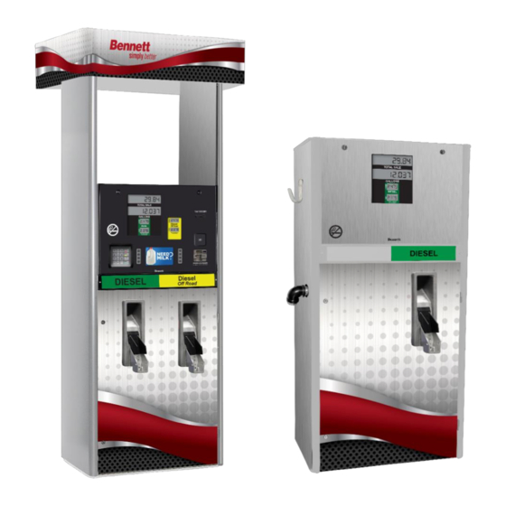
BENNETT 3000 SERIES DISPENSER
3000 Series Electronic Remote and Self-Contained Dispensers Retail-Commercial
Safety Information | Product Introduction | Preliminary Install Information | Installation Instructions
Dispenser Operation | Service & Troubleshooting | Footprints & Wiring Diagrams
Only Trained Personnel May Work on This Equipment
READ THIS MANUAL
This manual has important information for safe installation and operation of this equipment. Read and understand this manual before
applying power. Keep this manual and tell all service personnel to read this manual. If you do not follow the instructions, you can cause
bodily injury, death, or damage to the equipment.
Instruction Manual
138000 Rev B 10/26/18
Bennett 1218 E. Pontaluna Road, Spring Lake, MI 49456
USA 800-235-7618 ~ Outside USA 231-798-1310
sales@bennettpump.com ~ www.bennettpump.com
Advertisement
Table of Contents
Troubleshooting

Related Manuals for Bennett 3000 SERIES


Summary of Contents for Bennett 3000 SERIES
- Page 1 BENNETT 3000 SERIES DISPENSER 3000 Series Electronic Remote and Self-Contained Dispensers Retail-Commercial Instruction Manual 138000 Rev B 10/26/18 Safety Information | Product Introduction | Preliminary Install Information | Installation Instructions Dispenser Operation | Service & Troubleshooting | Footprints & Wiring Diagrams...
- Page 2 For new manuals, visit our web page at IMPORTANT Examine the shipment immediately upon arrival to make certain there has been no damage or loss in transit. Bennett Pump Company, as shipper, is not liable for the hazards of transportation. Please make damage claims directly to the truck line.
-
Page 3: Table Of Contents
Bennett 3000 Series Spec 300 Instruction Manual Table of Contents TABLE OF CONTENTS TABLE OF CONTENTS SECTION 1: SAFETY INFORMATION General Information ............................................2 Hazardous locations ............................................2 Codes and Standards............................................2 Unauthorized Alteration of Bennett Products ..................................2 Abbreviations and Acronyms ........................................2 Americans with Disabilities Act (ADA) Requirements ................................. - Page 4 Wiring Diagrams .............................................. 73 Footprint Diagrams ............................................83 Bennett Limited Warranty for Product Installed in the United States – 3000 Retail & Commercial Bennett Limited Warranty for Product Installed in the United States - Big Fueler & BlueFueler Bennett International Warranty for Dispensers & Pumps...
-
Page 5: Section 1: Safety Information
Environmental Standards® Health, Safety, Security & Environment (HSSE) policies. Note: Bennett Pump highly recommends all technicians observe HSSE policies defined by the supplier. Bennett Pump does not impose any restrictions or additional requirements contained in Environmental Standards® Health, Safety, Security & Environment (HSSE) policies. -
Page 6: General Information
GENERAL INFORMATION Read this manual carefully and read all tags/labels attached to the 3000 series dispenser or pump before starting any maintenance and/or service. A dispenser or pump that is not properly maintained will not perform properly and will void the Bennett Limited Warranty. -
Page 7: Americans With Disabilities Act (Ada) Requirements
Bennett 3000 Series Spec 300 Instruction Manual Safety Information AMERICANS WITH DISAB ILITIES ACT (ADA) REQUIREMENTS To meet the technical requirements established by the American with Disabilities Act (ADA) per Chapter 3 (Building Blocks), Section 308 (Reach Ranges), and Section 309 (Operable Parts). The forward and side reach maximum height is 48 inches above the finish floor or ground. - Page 8 Bennett 3000 Series Spec 300 Instruction Manual Safety Information Page Intentionally Left Blank...
-
Page 9: Section 2: Product Introduction
SECTION 2: PRODUCT INTRODUCTION This manual covers the 3000 Series Spec 300 Electronic Commercial and Retail Dispensers and Pumps with 719 electronics. For programming information, please refer to the 719 Electronic CPU Technical and Dispenser Programming Manual. Contact Bennett Pump Technical Support for questions at 1-800-423-6638. -
Page 10: Overview
The key locks for the electronic door are located on either outside top edge of the door. The Key locks for the lower door of the 3000 Series are located on the left side (top and bottom) of the lower door panel. A key is shipped with each Lower Door dispenser. -
Page 11: Dispenser Controls And Instrumentation
Field wiring connections are terminated on the terminal strip and pulled into the electronic enclosure. DISPENSER CONTROLS AND INSTRUM ENTATION The following section provides a description of the controls and instrumentation used on a 3000 Series Spec 300 Dispenser. MANAGER’S KEYPAD... - Page 12 Bennett 3000 Spec 300 Series Instruction Manual Product Introduction POWER SWITCH A power switch is located on the 719 CPU Board that is used to turn the dispenser on and off. When the switch is in the off position, main power is removed from the electronic circuit board.
-
Page 13: Main Displays
Note: Use the down arrow to scroll to the next screen. VOLUME AUXILIARY PPV DISPLAY – DEF UNITS The Auxiliary PPV Display is used to view the price per volume for DEF Units used with the 3000 series dispenser. -
Page 14: Electronic- Overview
ELECTRONIC – OVERVIEW The electronics used on the 3000 series dispenser are located in the upper cabinet and lower cabinet for hydraulic control. All units have conformal-coated electronic boards to help protect them from moisture or foreign material damage. All major electronic board assemblies are environmentally tested and temperature cycled. - Page 15 2-wire protocol. RS485 wires should be twisted together no less than 3 turns per foot to reduce the effects of electrical noise on the communication circuit. Bennett highly recommends the use of twisted wires. Note: Belden shielded cable is accepted but the “drain”...
- Page 16 Pulse Unit, Pulse Period (PPS), and Pulse Ratio. Pulse Output – The pulse output allows the 3000 Series Mechanical interface to send pulse information to the Console and the Tank Gauge. The system can be programmed to output pulse ratio from 1:1. 10:1. 100:1, and 1000:1. The fleet system and tank gauge connected to the dispenser must provide 5 –...
-
Page 17: Hydraulic Component Overview
DUAL PHASE PULSERS (STANDARD FLOW) The 3000 series pulsers are dual phase electronics pulsers that pulse at a rate of 1024 pulses per gallon. These pulsers are physically mounted to the output shaft of the Bennett SB-100 meter. Note: There is one pulser for every meter. As fuel flows through the meter, the output shaft rotates and turns the pulser. - Page 18 TYPE 75 PUMPING UNIT (STANDARD FLOW) The Bennett Type 75 pumping unit is used to pump fuel at two standard flows of 22-gpm (80-lpm) or at 13 gpm (50-lpm). Dispensers using 60Hz power the 13-gpm pump requires a 250 Watt 1/3 HP motor and the 22-gpm pump uses a 560 Watt 3/4 HP motor. Dispensers using 50Hz power it should be noted that the 22-gpm pump at different speeds could be done by changing the pump pulley.
-
Page 19: Section 3: Preliminary Install Information
Bennett dispensers are shipped Ex-Works. This means that the title to the equipment passes to the purchaser at the time the equipment is loaded on the truck at our factory. Freight damage claims are the responsibility of the purchaser. Bennett will assist in preparing any damage claim, by helping identify and price any parts necessary to make needed repairs. -
Page 20: Underground And Aboveground Storage Tanks
60 feet. For Bennett Dispensers the horizontal section of pipe from the underground storage tank should be at least 18 inches below the surface at its highest point. If not, hot summer temperatures will convert the liquid in the pipe to vapor and stop the dispenser from functioning properly. -
Page 21: Mechanical And Plumbing Notes
All dispenser field wiring between the building and the dispenser for power, neutral and ground wire conductors must not be spliced, wire nutted or shared with any other equipment. Doing so would void the Bennett Limited Warranty. All power, neutral and ground conductors shall be run from the dispenser to the Main Service Panel. -
Page 22: Preparing Field Wiring
All underground conduit should be rigid metal and drawn up tight. The use of PVC (plastic) conduit is not allowed and may void the Bennett Warranty. Make sure that vapor “seal offs” are properly installed on all conduits at and from each dispenser. Make sure any intercom wiring is not run with dispenser field wiring. -
Page 23: Step 1 - Determine The Model Number
Identifying the features of the unit prior to installation will provide an understanding of how to perform an accurate installation. Follow the steps below to determine what type of 3000 Series Electronic Dispenser you are installing. DIN numbers are used to identify what type of dispenser or pump is being used and options used. Determine the model number of the dispenser from the serial label located on Side 1 of the dispenser. -
Page 24: Step 2 - Determine Side 1 And Side 2 Of The Unit
STEP 3 - DETERMINE THE TYPE OF DI SPENSER SUMP Before placing a 3000 Series Electronic Dispenser onto an island, determine what type of dispenser sump is used and follow the original manufacturer’s installation instructions. Review the Bennett 3000 Series Electronic Dispenser Footprint for your unit and get the measurements of the existing or new dispenser sump to determine if any adjustments are needed prior to mounting the unit onto the island. -
Page 25: Step 5 - Find Dispenser Footprint
Bennett 3000 Spec 300 Series Instruction Manual Preliminary Install Information STEP 1: Determine the type of supply line needed from the model number’s seventh position on the serial label. R = Remote Dispensers will require a submerged pump and pressurized supply line for each product. - Page 26 Bennett 3000 Spec 300 Series Instruction Manual Preliminary Install Information Page Intentionally Left Blank...
-
Page 27: Section 4: Installation Instructions
Bennett 3000 Spec 300 Series Instruction Manual Installation Instructions SECTION 4: INSTALLATION INSTRUCTIONS LIFTING A NEW DISPEN SER Follow the instructions below for proper directions on lifting a new dispenser. Unlock the lower door using the keys provided with the unit and remove the door (swing the door open 90 degrees lift and store in a safe place until it is ready to be installed. -
Page 28: Anchoring The Dispenser To The Island
When anchoring the dispenser, always level the dispenser with metal shims before bolting to the island. Place the metal shims at the location of the anchor bolts so the dispenser frame is not distorted when the anchor bolts are tightened down. Improper shimming that result in misaligned frames is NOT covered under the Bennett Limited Warranty! WIRING THE DISPENSER Follow the sections below for proper equipment grounding, dispenser AC power, and console communication. - Page 29 To be used with Fleet Management Systems BENNETT CURRENT LOOP FUEL COMMUNICATION (121982) To be used with Bennett 515 Box, TMX, Comdata, FIS-CAL, VeriFone Commander, Ruby, and Sapphire remote consoles. Bennett Current Loop uses a 4-wire protocol. Use the table below to determine how many wires your communication console requires and the connection points for this type of communication.
- Page 30 TS2, PIN 3 CARD READER COMMUNIC ATION (OPTIONAL) Bennett Dispensers can interface with many POS terminals as well as site controllers. Refer to the sections below to determine what type of communication is used and what fueling controller is needed for communication.
- Page 31 Intercom wiring must be in a separate conduit from the dispenser conduit. DO NOT install intercom wiring in the same conduit as the dispenser wiring or else the Bennett Warranty will be voided and improper system operation will result. If the dispenser is ordered with an intercom (speaker and call button), the Installer must pull wires for it.
- Page 32 MECHANICAL PULSE OUT PUT 131480 (OPTIONAL ) The field wiring will be connected between a Bennett Pulse Output Board and the third party interface system. This board is mounted on the 719 CPU inside the electronics enclosure. One Pulse Output Board can handle up to two hoses (products). Note: Active 4 units can use two Pulse Output Boards.
- Page 33 Bennett 3000 Spec 300 Series Instruction Manual Installation Instructions 2 PRODUCT CONNECTION 16-FIELD WIRES REQUIRED (135046) DIRECT PULSE OUTPUT BOARD WIRING Wiring is to be connected directly to the Pulse Output Board. Description Size Wire Color To Terminal (Controller) Pulse Out (+) Product 1...
-
Page 34: Potting Instructions
Bennett 3000 Spec 300 Series Instruction Manual Installation Instructions OPTIONAL JUNCTION BOX CONNECTION - 2 FIELD WIRES (REQUIRED) Description Size Wire Color To Connection RS485 (+ positive) Orange Terminal 20 RS485 (- negative) Brown Terminal 21 POTTING INSTRUCTIONS Wrap some CHICO X fiber around wires and push into conduit assembly to prevent potting from running down the length of the conduit. -
Page 35: Section 5: Dispenser Operation
Bennett 3000 Spec 300 Series Instruction Manual Dispenser Operation SECTION 5: DISPENSER OPERATION The explanations given in the menus listed in this section are intended for use by the operator, manager, or service technician. HOW TO POWER UP THE DISPENSER... - Page 36 Bennett 3000 Spec 300 Series Instruction Manual Dispenser Operation SUGGESTED SETUP SEQU ENCE The software program for each new dispenser shipped from the factory is pre-programmed with the default settings in some of the Menu Codes. Make sure the initial setup menu codes are programmed before testing any dispenser operations. Failure to do so may lead to difficulty getting the dispenser to operate properly.
-
Page 37: How To Start-Up Dispenser And Checklist
If the resistance reading is more than 1 ohm, the dispenser electronics may not operate properly and will void the Bennett Limited Warranty. Turn on 120 or 240 volts ac dispenser power to the unit. -
Page 38: How To Purge Product Lines For Remote Dispensers
Bennett 3000 Spec 300 Series Instruction Manual Dispenser Operation The suction pump's motor for Product A has two wires coming into the electrical enclosure. One motor wire connects to TS2, terminal 2 of the CPU Board (factory connected) and the other wire is left detached for the installer to connect the pump motor's neutral, which comes directly from the Circuit Breaker or Phase 2 if using 240 volts to run the Product A motor. -
Page 39: How To Purge Product Lines For Suction Systems
Bennett 3000 Spec 300 Series Instruction Manual Dispenser Operation HOW TO PURGE PRODUCT LINES FOR SUCTION SYSTEMS The Suction pump product lines must be purged of all air that may be trapped in the lines. All electrical connections must be made and verified at this time. -
Page 40: How To Dispense Fuel
Bennett 3000 Spec 300 Series Instruction Manual Dispenser Operation THE OPTIONAL CALIBRATION PROCEDURE This procedure assumes that the test can sight glass is graduated in test can percentage units rather than cubic inches or cubic centimeters (milliliters) as in the basic calibration procedure. If the sight glass is in cubic inches or cubic centimeters, refer to The Basic Calibration Procedure. -
Page 41: How To Run A Sale
Bennett 3000 Spec 300 Series Instruction Manual Dispenser Operation HOW TO RUN A SALE The following instructions are for general payment terminal operation. Note: The Local Preset option and the SSP option are mutually exclusive. A dispenser may have either option, but cannot have both. -
Page 42: How To Read The Last Sale During A Power Failure
Bennett 3000 Spec 300 Series Instruction Manual Dispenser Operation HOW TO READ THE LAST SALE DURING A POWER FAILURE If an AC power failure occurs, the dispenser will display the last sale in progress at the time of Sale $ the failure. -
Page 43: Section 6 Service &Troubleshooting
ELECTRONIC COMPONENT S The electronics used on the 3000 series dispenser are located in the upper cabinet and lower cabinet for hydraulic control. All units have conformal-coated electronic boards to help protect them from moisture or foreign material damage. All major electronic board assemblies are environmentally tested and temperature cycled. - Page 44 THE INTRINSICALLY SAFE BARRIER HAS SPECIAL FUSES THAT ARE SOLDERED ONTO THE BOARD AND CANNOT BE REPLACED IN THE FIELD. IF A FUSE HAS BLOWN ON THE BOARD, IT MUST BE SENT BACK TO BENNETT PUMP FOR REPAIR. IF YOU TRY TO FIELD REPAIR THIS BOARD, INJURY OR DEATH COULD RESULT DUE TO AN EXPLOSION OR FIRE AT THE PUMP.
- Page 45 Bennett 3000 Spec 300 Series Instruction Manual Service & Troubleshooting Side 1 Main Display A 20-position gray ribbon cable header connects to the Main Display. This is used to connect to the Main Display on Side 1 of the dispenser. Note: (Volume/Volume Twin/Volume Side Mount/Retail/Retail Twin/Retail Side Mount).
- Page 46 Bennett 3000 Spec 300 Series Instruction Manual Service & Troubleshooting Side 2 Satellite Valve Output A 4-position header uses wire harness to connect to the Satellite Board for valve control. The Satellite Board controls the valve in the Master and the valve in the Satellite unit.
- Page 47 WARNING: FAILURE TO PROPERLY GROUND THE EQUIPMENT CAN CAUSE INJURY OR DAMAGE TO THE EQUIPMENT AND WILL VOID THE BENNETT LIMITED WARRANTY. DO NOT USE WIRE NUTS ON GROUND CIRCUITS, USE ONLY COMPRESSION TYPE CONNECTORS. DO NOT TERMINATE AT THE NEUTRAL BAR OF A SUB-PANEL OR RELY ON METAL CONDUIT FOR THIS GROUND CONNECTION.
- Page 48 Bennett 3000 Spec 300 Series Instruction Manual Service & Troubleshooting Product A PIN Terminal (Jumper) The P1 PIN terminal is used for submersible motor A control on remote units. The P1 and P3 jumpers MUST BE connected for the 1 product.
- Page 49 Bennett 3000 Spec 300 Series Instruction Manual Service & Troubleshooting FUSES There is fuse protection on the 719 CPU for incoming AC voltage and for power traveling throughout the system. The standard glass body fuses listed below are located on the 719 CPU as shown below.
- Page 50 The 419 Lower I/O Board is a low power circuit board that provides power, control, and/or temperature compensation to the hydraulics of any Bennett electronic commercial and retail dispensers. Refer to the 419 Technical Manual for more information. COMPONENT DESCRIPTION An assortment of components have been installed on the circuit board including resistors, capacitors, headers, and filters.
- Page 51 Bennett 3000 Spec 300 Series Instruction Manual Service & Troubleshooting Product A Thermistor Probe Input A 2-position ribbon cable header is used to connect to the product A thermistor probe input. Description Probe input Ground Pump Handle Input (Side 1) A 8-position ribbon cable header connects to the pump handle switches.
- Page 52 Current Loop communication uses terminal strips TS1 (side 1) and TS2 (side 2). The figure below shows the typical 719 CPU Board layout for a current loop personality module. COMPONENT DESCRIPTION The following is a description of the terminal strips and pinouts used on the Bennett Current Loop and Generic Current Loop personality module. Side 1...
- Page 53 2-wire protocol. RS485 wires should be twisted together no less than 3 turns per foot to reduce the effects of electrical noise on the communication circuit. Bennett highly recommends the use of twisted wires. Note: Belden shielded cable is accepted but the “drain”...
- Page 54 Bennett 3000 Spec 300 Series Instruction Manual Service & Troubleshooting PULSE OUTPUT BOARD ( FLEET MANAGEMENT SYSTEMS) The pulse output board connects to the 719 CPU on connector J7. It supports up to two fueling positions on the single RS485 connection.
- Page 55 Bennett 3000 Spec 300 Series Instruction Manual Service & Troubleshooting RS485 Controller (Optional) The TS4 connections uses a 3-pin header for RS485 communication for a pulse output signal for a Tank Gauge. Description 17 (orange) RS485 (+ positive) Not Used...
- Page 56 Bennett 3000 Spec 300 Series Instruction Manual Service & Troubleshooting COMPONENT DESCRIPTION The following is a description of the terminal strips and pinouts used on the optional Satellite Board. 120V AC Power The J1 connection is a 3-position mini header used to receive 120VAC power from the 719 CPU.
- Page 57 Bennett 3000 Spec 300 Series Instruction Manual Service & Troubleshooting LIGHT EMITTING DIODES One LED is available as shown in Figure xx that can be used for troubleshooting. See below for more information. Color Description Green ON/OFF – Handle In Use CONTACTOR BOARD 3-PHASE (P/N 133598 FOR 120VAC OR 133607 FOR 240VAC) The contactor board is used for 3-Phase (380VAC) Suction Pump Motor Control.
- Page 58 Bennett 3000 Spec 300 Series Instruction Manual Service & Troubleshooting NOZZLE BOOT WITH LEVER 4.0 ASSEMBLY (P/N 125270) The nozzle boot uses a lever (lift-to-start), handle switch assembly to identify what product the customer wants to dispense, and signals the Lower I/O board to turn on the proper pump motor. The handle switch is located on the back of the Nozzle Boot near the bottom as shown in the figure below.
-
Page 59: Hydraulic Components
DUAL PHASE PULSERS (STANDARD FLOW) The 3000 series pulsers are dual phase electronics pulsers that pulse at a rate of 1024 pulses per gallon. These pulsers are physically mounted to the output shaft of the Bennett SB-100 meter. Note: There is one pulser for every meter. As fuel flows through the meter, the output shaft rotates and turns the pulser. - Page 60 Bennett 3000 Spec 300 Series Instruction Manual Service & Troubleshooting PULSER CONNECTION CAUTION: WHEN CONNECTING A PULSER NEVER CONNECT A PULSER OR DISCONNECT A PULSER WITHOUT TURNING OFF THE DISPENSER POWER AND BATTERY. DAMAGE TO THE PULSER OR THE LOWER I/O BOARD CAN OCCUR IF POWER IS LEFT ON..
- Page 61 SB-100 METER (MECHANICAL OR ELEC TRONIC) The Bennett SB-100 meter is used to measure the flow of fuel in the ‘Standard Flow’ 3000 Dispenser. It is a volumetric meter employing four pistons with seals and associated chambers. The SB-100 meter maintains a .3% accuracy for flow rates from 1.3GPM (5LPM) to 26 GPM (100 LPM).
- Page 62 Master unit operates off +24 VDC. The Big Fueler 3000 series dispenser uses a 1-1/2” +24 VDC 2-stage valve. Note: Except for the 2 stage valves used in the Satellite of a Master / Satellite system which uses 120/240 VAC valves. Note: A commercial dispenser may have only one or up to four 2-stage valves.
- Page 63 Bennett 3000 Spec 300 Series Instruction Manual Service & Troubleshooting COMPONENT DESCRIPTION A 3-wire connection connects to J10 (side 1) and/or J7 (side 2) of the 719 CPU for valve control. This valve is also the Side 1 valve for the second product when the dispenser is configured as 2 side and 2 grades (e.g.
- Page 64 PROPORTIONAL VALVE CONTROL (STANDARD FLOW) The standard flow 3000 series dispenser uses a 1” (2-wire) proportional valve. The proportional valves are +24-volt valves that contains a plunger, spring, O-rings, and diaphragm. The way the proportional valves handle a preset or a prepay sale is to modulate the proportional valves for the two gas products to slowly close off the valve at the end of a sale.
- Page 65 Bennett 3000 Spec 300 Series Instruction Manual Service & Troubleshooting HOW TO TEST THE VOLTAGE The valves can be tested for proper voltage readings via Wire to Wire or Wire to Chassis. Refer to the table below for a brief instruction.
- Page 66 Bennett 3000 Spec 300 Series Instruction Manual Service & Troubleshooting HOW TO TEST THE VALVE To test the two-stage valve follow the testing procedures below. CHECK FOR PROPER FUEL FLOW The best way to check a valve is to pump fuel and see if you are getting full flow. You can do this by pumping into a test bucket as shown below.
-
Page 67: Main Displays
Bennett 3000 Spec 300 Series Instruction Manual Service & Troubleshooting MAIN DISPLAYS The Main Displays are used to display Currency (Total Sale), Volume (Gallons or Liters), PPV (Price per Volume), Totalizer information, programming, error codes, as well as certain prompting messages, and can have an optional Satellite ‘In Use’ light. - Page 68 Bennett 3000 Spec 300 Series Instruction Manual Service & Troubleshooting COMMERCIAL DISPLAY ( VOLUME ONLY) The Commercial Display shows the volume only in gallons or liters. It also is used to view programming modes, error codes, as well as certain prompting messages.
- Page 69 Bennett 3000 Spec 300 Series Instruction Manual Service & Troubleshooting AUXILIARY DISPLAY The Auxiliary PPV Display is used to view the price per volume for DEF Units used with the 3000 series dispenser. FRONT VIEW BACK VIEW COMPONENT DESCRIPTION The following is a description of the terminal strips and pinouts used on the Volume Only Displays.
-
Page 70: Troubleshooting
This section of the manual was designed to break down individual problems with the most common symptoms and corrective actions. This information comes directly from the Help Desk at Bennett from problems that have been seen in the field. IMPORTANT The “Possible Causes”... - Page 71 Bennett 3000 Spec 300 Series Instruction Manual Service & Troubleshooting PROBLEM 2: NO DISPLA Y Refer to the table below for a description of various causes of the problem and the solution. CAUSE SOLUTION Breaker Turned Off Turn Breaker On Fuse Blown on CPU Test Fuse F1.
-
Page 72: Error Codes
Diagnostic Code 2 for more information. Note: Repair the problem that may have caused the error first and then clear the message. If an error message continues to be displayed, please contact Bennett Technical Support at 1- 800-423-6638. -
Page 73: Electronic Spare Parts
Bennett 3000 Spec 300 Series Instruction Manual Service & Troubleshooting Error Code Error Text Description 6-Digit Display 8-Digit Display VSIDE2 VACSIDE2 Vapor Vacuum – Side 2 Error – Fast Flow or Over Current VAPOR VAPOR TST Vapor Recover Error Signal Received... - Page 74 Bennett 3000 Spec 300 Series Instruction Manual Service & Troubleshooting Page Intentionally Left Blank...
-
Page 75: Section 7 Footprints & Wiring Diagrams
Bennett 3000 Spec 300 Series Instruction Manual Footprint & Wiring Diagrams SECTION 7 FOOTPRINTS & WIRING DIAGRAMS CPU SYSTEM BLOCK DIAGRAM... -
Page 76: Big Fueler Flow Curves
Bennett 3000 Spec 300 Series Instruction Manual Footprints & Wiring Diagrams BIG FUELER FLOW CURVES Flow Curve Big Fueler Inlet Pressure (PSI) Flow Curve Big Fueler Pressure Drop (PSI) -
Page 77: Wiring Diagrams
Read all NOTES, DANGERS, CAUTIONS, WARNINGS, and IMPORTANT statements before performing any installation, operation, maintenance, troubleshooting, or service. Wiring diagrams and footprints can be found in the electronic enclosure of the dispenser or on the CD-ROM/USB located inside the dispenser. BENNETT CURRE NT LOOP 719 WIRING D IAGRAM (P/N 135043) - Page 78 Bennett 3000 Spec 300 Series Instruction Manual Footprints & Wiring Diagrams GENERIC CURRENT LOOP 719 WIRING DIAGRAM (P/N 135044)
- Page 79 Bennett 3000 Spec 300 Series Instruction Manual Footprints & Wiring Diagrams RS485 719 WIRING DIAGRAM (P/N 135048)
- Page 80 Bennett 3000 Spec 300 Series Instruction Manual Footprints & Wiring Diagrams RS232 PORT BOARD 719 WIRING DIAGRAM (MEXICO USE ONLY) (P/N 135305)
- Page 81 Bennett 3000 Spec 300 Series Instruction Manual Footprints & Wiring Diagrams PULSE OUTPUT BOARD W IRING DIAGRAM (P/N 135046)
- Page 82 Bennett 3000 Spec 300 Series Instruction Manual Footprints & Wiring Diagrams MASTER/SATELLITE WIRING DIAGRAM (P/N 135045)
- Page 83 Bennett 3000 Spec 300 Series Instruction Manual Footprints & Wiring Diagrams REMOTE AC POWER AND MOTOR WIRING DIAGRAM (P/N 135047)
- Page 84 Bennett 3000 Spec 300 Series Instruction Manual Footprints & Wiring Diagrams SUCTION AC POWER AND MOTOR WIRING DIAGRAM (P/N 135050)
- Page 85 Bennett 3000 Spec 300 Series Instruction Manual Footprints & Wiring Diagrams TRUCK PUMP SUCTION AC POWER AND MOTOR WI RING DIAGRAM (P/N 135085)
- Page 86 Bennett 3000 Spec 300 Series Instruction Manual Footprints & Wiring Diagrams SUCTION AC POWER AND 3-PHASE MOTOR WIRING DIAGRAM (P/N 135049)
-
Page 87: Footprint Diagrams
Bennett 3000 Spec 300 Series Instruction Manual Footprints & Wiring Diagrams FOOTPRINT DIAGRAMS REMOTE | HIGH HOSE A ND LOW HOSE | STANDA RD FLOW RATES (P/N 137778) - Page 88 Bennett 3000 Spec 300 Series Instruction Manual Footprints & Wiring Diagrams SUCTION | HIGH HOSE AND LOW HOSE | STANDARD FLOW RATES (P/N 137779)
- Page 89 Bennett 3000 Spec 300 Series Instruction Manual Footprints & Wiring Diagrams REMOTE | QUAD OR ACTIVE 4 | HIGH HOSE | STANDARD FLOW RATES (P/N 137780)
- Page 90 Bennett 3000 Spec 300 Series Instruction Manual Footprints & Wiring Diagrams SUCTION | QUAD| HIGH HOSE | STANDARD FLO W (P/N 137781)
- Page 91 Bennett 3000 Spec 300 Series Instruction Manual Footprints & Wiring Diagrams REMOTE | MASTER / CO MBO | LOW HOSE | HIG H FLOW BIG FUELER (P/N 137782)
- Page 92 Bennett 3000 Spec 300 Series Instruction Manual Footprints & Wiring Diagrams REMOTE | SATELLITE | LOW HOSE | HIGH FLO W BIG FUELER (P/N 137783)
- Page 93 Bennett 3000 Spec 300 Series Instruction Manual Footprints & Wiring Diagrams SUCTION | HIGH AND L OW HOSE| HIGH FLOW BIG FUELER (P/N 1377784)
- Page 94 Bennett 3000 Spec 300 Series Instruction Manual Footprints & Wiring Diagrams REMOTE | MASTER | HI GH HOSE | HIGH FLOW BIG FUELER (P/N 137785)
- Page 95 Bennett 3000 Spec 300 Series Instruction Manual Footprints & Wiring Diagrams REMOTE | SATELLITE | HIGH HOSE | HIGH FLOW BIG FUELER (P/N 137786)
- Page 96 Bennett 3000 Spec 300 Series Instruction Manual Footprints & Wiring Diagrams REMOTE | COMBO | HIG H HOSE | HIGH FLOW B IG FUELER (P/N 137787)
- Page 97 Bennett 3000 Spec 300 Series Instruction Manual...
- Page 98 Bennett 3000 Spec 300 Series Instruction Manual...
- Page 99 Bennett 3000 Spec 300 Series Instruction Manual...
- Page 100 Bennett 1218 E. Pontaluna Road, Spring Lake, MI 49456 USA 800-235-7618 ~ Outside USA 231-798-1310 sales@bennettpump.com ~ www.bennettpump.com...
Need help?
Do you have a question about the 3000 SERIES and is the answer not in the manual?
Questions and answers