Table of Contents
Advertisement
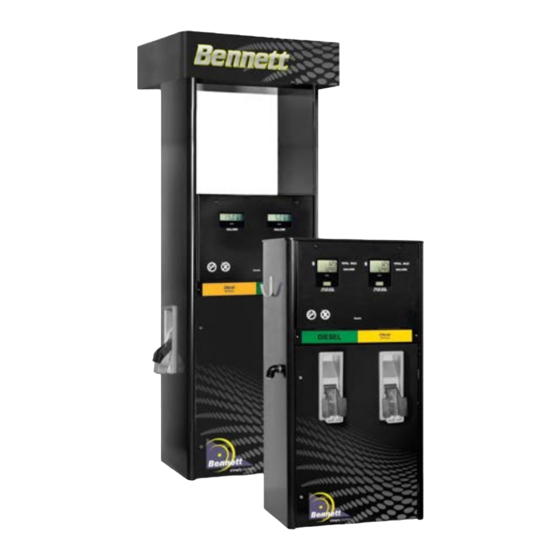
Bennett Pump Company
Commercial and Retail Dispensers
3700/3800 Series Spec. 100 (2nd Generation)
Electronic Commercial & Retail Installation Manual
Only Trained Personnel May Work on This Equipment
Includes Instructions For:
All 3700 Electronic Commercial Dispensers
All 3800 Electronic Retail Dispensers
Remote Dispensers
Self-Contained Pumps
READ THIS MANUAL
This manual has important information for safe installation and
operation of this equipment. Read and understand this manual
before applying power. Keep this manual and tell all service
personnel to read this. If instructions are not followed then
bodily injury, death or damage to the equipment may occur.
For new manuals, FAX to:
BENNETT MARKETING
SERVICES
(231)799-6202
or visit our web page at:
http://www.bennettpump.com
Bennett 1218 E. Pontaluna Road, Spring Lake, MI 49456
USA 800-235-7618 Outside USA 231-798-1310 sales@bennettpump.com
and
120001 Rev K 1-19-18
www.bennettpump.com
Advertisement
Chapters
Table of Contents

Related Manuals for Bennett 3700 Series


Summary of Contents for Bennett 3700 Series
- Page 1 For new manuals, FAX to: BENNETT MARKETING SERVICES (231)799-6202 or visit our web page at: http://www.bennettpump.com 120001 Rev K 1-19-18 Bennett 1218 E. Pontaluna Road, Spring Lake, MI 49456 www.bennettpump.com USA 800-235-7618 Outside USA 231-798-1310 sales@bennettpump.com...
-
Page 2: Table Of Contents
Audit Form ....................................83 PCI SSC - Legal Terms and Conditions ............................85 Bennett Limited Warranty for Products Installed in the United States - 3000 Retail & Commercial ..........86 Bennett International Limited Warranty for Dispensers and Pumps ....................87 NOTICE Not all equipment covered in this manual is listed by Underwriters Laboratories. -
Page 3: Safety Instructions
Environmental Standards® Health, Safety, Security & Environment (HSSE) policies. Note: Bennett Pump highly recommends all technicians observe HSSE policies defined by the supplier. Bennett Pump does not impose any restrictions or additional requirements contained in Environmental Standards® Health, Safety, Security & Envi- ronment (HSSE) policies. -
Page 4: Introduction For The 3000 Series Electronic Commercial And Retail Dispensers
Hydraulics Simplified electronic computer. Precision Bennett SB100 Meter, 4-piston, positive displacement design. Stand-alone or Interfaced to Control Device. Type 75 or type 75-HD Bennett sliding vane RS485 interface. pumping unit with integral vortex Exclusive eCal (Electronic Calibration). - Page 5 Simplified electronic computer. Precision Bennett SB100 Meter, 4-piston, positive displacement design. Stand-alone or Interfaced to Control Device. Type 75 or type 75-HD Bennett sliding vane RS485 interface or current loop or dual pulse pumping unit with integral vortex output (i.e.
- Page 6 Long life, highly visible back lighted LCD Units have been tested and found Bennett dispensers may dispense display, 1” (2.54cm) numerals. “Av-Gas”, but cannot dispense Jet to comply with the limits for a Class ...
- Page 7 & hose models in single or dual style. Note: volume totals. duals are two sided only). Current loop Bennett fuel protocol interface. For further details about satellite models, see Field wiring goes directly to terminal strip on our Product Cut Sheet for Satellites.
-
Page 8: Determining The Model Number
Determining the Model Number Determine the model number of the dispenser from the serial plate located on the dispenser. Utilizing the chart below determine the features of the dispenser to be installed. Understanding the features of the dispenser to be installed will be helpful in understanding the proper installation of the dispenser. How a Model for the 3000 Series Dispensers is Made Up. -
Page 9: Product Specifications
Product Specifications POWER REQUIREMENTS AC Power Input, Electronic ..........Universal Input 85-270 Volts A.C. 50/60 Hz. DC Power Supply Outputs ..........+5VDC 100mA Max, +12 VDC 100mA Max. DC Power Supply Outputs ......+24 VDC 1.0 Amps Max., +5 VDC Isolated 50mA Max Nickel-Cadmium Battery Output ............ -
Page 10: Dispenser Identification Number Summary (Din)
Dispenser Identification Number Summary (DIN) 3000 Electronic - Standard Flow 120001 Rev K 1-19-18... - Page 11 Dispenser Identification Number Summary (DIN) 3000 Electronic - High Flow 120001 Rev K 1-19-18...
-
Page 12: Unloading, Unpacking And Inspecting A New Dispenser
If possible, open the carton and inspect the dispenser before signing the delivery receipt. Bennett dispensers are shipped Ex-Works. This means that the title to the equipment passes to the purchaser at the time the equipment is loaded on the truck at our factory. Freight damage claims are the responsibility of the purchaser. -
Page 13: Lifting A New Dispenser And Placing It On The Island
Lifting a New Dispenser and Placing it on the Island The dispenser is bolted to a pallet with bolts and nuts. With the lower doors removed and safely stored away, remove the nuts and bolts that secure the dispenser to the pallet as shown in figure 1 and figure Figure 1 - Unlock the lower door with the keys Figure 2 - Remove the door and store in a safe that come with the unit. -
Page 14: Alternative Method For Lifting The Dispenser - High Hose
Lifting a New Dispenser and Placing it on the Island Alternate Method for High Hose Lifting the Dispenser from Above - On the high hose models, there are lifting brackets provided in the upper area of the dispenser. There is a cover that has to be removed to access these brackets. (See figure 5 and figure 6 below). -
Page 15: Determining The Number Of Product Supply Pipes Needed
Determining the Number of Product Supply Pipes Needed Step 1: Determine the type of supply line needed from the model number’s 7th position on the serial tag. If the model number is 3711SNR (Note the R) the dispenser will require a submerged pump and pressurized supply line for each product. -
Page 16: Pipelines And Underground Containment Sumps
The dispenser must be mounted on a concrete foundation. Do not pour concrete around the product pipes or electrical conduit. The use of a UL approved containment sump designed for the Bennett Dispenser Model used is highly recommended. Follow the containment sump manufacture’s installation instructions for proper installation. -
Page 17: Above Ground Tank Installation With Self Contained Pumps
Above Ground Tank Installation with Self Contained Pumps Bennett self contained dispensers can be used with aboveground tank installations if the following requirements are met: An Underwriters (U.L.) Listed Pressure Regulating Valve designed for under-the-pump mounting is installed for each pumping unit according to the valve manufacturer’s instructions. -
Page 18: Electrical Field Wiring - General Information
Bennett’s limited warranty. Intercom wiring must be in a separate conduit from the dispenser conduit. DO NOT install intercom wiring in the same conduit as the dispenser wiring or else the Bennett Warranty will be voided and improper system operation will result. - Page 19 All underground conduit should be rigid metal and drawn up tight. The use of PVC (plastic) conduit is not allowed and may void the Bennett Warranty. Make sure that vapor “seal offs” are properly installed on all conduits at and from each dispenser. Make sure any intercom wiring is not run with dispenser field wiring.
-
Page 20: Purging Product Lines For Remote Dispensers
RUNNING THE METER IN A DRY CONDITION AND AT THE HIGH SPEEDS RESULTING FROM PRESSURIZED AIR, WILL DAMAGE THE METER AND VOID THE BENNETT LIMITED WARRANTY. The emergency shutoff valve contains a test port that may be used to bleed off air that may be trapped in the product lines. -
Page 21: Piping Notes For Self Contained Systems
Piping Notes for Self-Contained Systems To obtain maximum flow rates on a self-contained pump, follow these guidelines (see figure 14): The total length of horizontal piping between the pump and tank must be no longer than 60 feet. Use new 1-1/2” galvanized or approved non-metallic pipe for 10-15gpm pumps. Use new 2” galvanized or approved non-metallic pipe for 20-24 gpm pumps. -
Page 22: Wiring The 3700 Series Dispenser (Commercial)
Wiring the 3700 Series Dispenser Commercial See General Wiring Requirements on pages 16, 17 120001 Rev K 1-19-18... -
Page 23: Determine The Number Of Wires Needed
Determine the Number of Wires Needed 115 or 230 Volt Installations The 531 commercial electronics package in the model 3700 unit is a very simple design. There will be one “control” (CPU) board per hose. The dispenser may be ordered as a one or two hose unit. One hose units have one control board, and two hose units have two control boards. - Page 24 (1) Authorization wires per CPU/Control Board (+) and (-) 18 ga. * Note - The field wiring will be connected between a Bennett Pulse Output Board and the third party interface system. This board will be mounted on the deck inside the electronics enclosure. One Pulse Output Board can handle two CPU/Control Boards per Product.
-
Page 25: Pulling The Field Wires
WARNING: Failure to properly ground the equipment can cause injury or damage to the equipment and will void the Bennett limited warranty. This product must be properly grounded. Each dispenser requires a 12-gauge Green earth ground wire. Grounding provides a path of least resistance for electric current to reduce the risk of electric shock. -
Page 26: Ac Power Installation
AC Power Installation Each dispenser uses one 115V, 50/60 Hz or 230V, 50/60 Hz circuit for dispenser power. Make sure the power source has the correct frequency and voltage. Connect the electrical circuit to the terminal strip on the CPU board. Only one dispenser electronics Hot and Neutral needs to be pulled per dispenser. That power will be jumped from Control Board to Control Board in the electronics head (at the factory) if there is more than one Control Board in the dispenser. -
Page 27: Installing Rc Networks
50ft. 12Ga. for runs to 100ft, 10ga.for runs over 100ft, and 8 ga. for runs over 200 feet. Pump motor power must be on a different phase leg than the dispenser power or system malfunction will result and the Bennett Limited Warranty will be voided. Termination of Field Wiring for Pump Motor Power of Self-Contained Dispensers... -
Page 28: Connecting The Communication Wiring
Connecting Pump Motor Power for Suction Pump Systems Connecting Pump Motor Power for Self-Contained Pumps Product “A” Suction Pump Motor Control (120VAC / 240VAC) - Connect the Blue 14ga. L1 - 120 or 240VAC (HOT) wire from the second motor power circuit breaker to terminal 4 of TS2 on the CPU board. -
Page 29: Connecting Field Wiring To The Mechanical Interface Board
Connecting Field Wiring to the Mechanical Interface Board Mechanical Mode - Mechanical Mode allows the 3000 series to imitate a mechanical dispenser and interface to a Fleet System. It also allows pulse output communication with a Tank Gauge. A separate Mechanical Pulse Output Interface Board is required for the dispenser. There will be one Pulse Output board for a single product (single hose or twin) dispenser . -
Page 30: Pulse Output Field Wiring Table
Pulse Output Field Wiring Table (Also refer to as the Pulse Output Wiring Diagram) Name Color Wire J-Box Connection Board Connection Size (Optional) Tank Gauge Out Product A side 1 Gray 1(+) 18 Ga. Flying Lead Gray Product A TS1-3 Pulse Output Board Product A Marked 1(+) Tank Gauge Out Product A side 1 Gray 1(-) 18 Ga. -
Page 31: Setting The Jumpers On The Pulse Output Board
Setting the Jumpers on the Pulse Output Board The Pulse Output board is ordered as an option with the Electronic 3000 series. This board is where the field wires connect the 3rd party Fleet System to the Pulse Output functions of the dispenser. This board also has jumpers that need to be set to determine the Pulse Rate and the Pulse Width. -
Page 32: Cpu Board Jumper Configuration
CPU Board Jumper Configuration The 3700 Series can operate in two different modes, Console or Stand Alone, which must also be defined by jumper settings on the CPU board: Stand Alone Mode -Stand Alone mode allows the 3700 Series to operate without being connected to a console or control device. -
Page 33: Cpu Board Jumper Configuration - Diagram
Jumper Positions 1 - 4 - (Fueling Point Address - Up to 16 fueling position addresses). Use jumper positions 1 through 4 to set the dispenser address. Normally, Bennett pumps do not need an address set when using current loop communications but with RS 485 style communication an address must be set for the 3rd party device or console to know which fueling point it is talking to. - Page 34 CPU Board Jumper Configuration Jumper Header JP1 on the CPU board is used to program the dispenser and to set the hose position address. The first 4 rows are used to set the hose position address. Addresses from 1-16 are available. Figure 24 shows how to set the address using the first four rows of the Jumper Header.
-
Page 35: Dispenser Startup And Checklist
This ensures that the resistance read is not across the electronics on the circuit board. If the resistance reading is more than 1 ohm, the dispenser electronics may not operate properly and will void the Bennett Limited Warranty. Turn on 115 or 230 Volts AC dispenser power to the unit. - Page 36 Dispenser Startup and Checklist Self-Contained WARNING: If the lower door on the pulley side of the unit is off, close the door and lock it to prevent injury. 1. Verify that the motor voltage select switch on the self contained motor is in the proper position. (if applicable) 2.
-
Page 37: Potting Instructions
Potting Instructions 1. Install field conduit in the dispenser per NFPA-70 along with any state and local codes. 2. Pull field wiring allowing 72 inches of extra wire to reach upper electrical enclosure. 3. Feed wire through conduit and into upper electrical enclosure CAUTION: Do not damage wire while feeding through conduit into the upper electrical enclosure. -
Page 38: How To Mechanically Calibrate The Sb-100 Meter (M-Cal Option)
We strongly suggest recalibration of the meter after a 90 day break in period. With the 3700 series electronic dispenser, mechanical calibration is optional. The standard 3700 is calibrated electronically. This means that the meter in the dispenser may not be able to be calibrated mechanically (it will not have a mechanical calibration wheel). -
Page 39: How To Electronically Calibrate The Sb-100 Meter (E-Cal)
How to Electronically Calibrate the SB-100 Meter (E-Cal Option) Electronic calibration is a simple method to calibrate the meters in the dispenser. This method uses a mathematical algorithm in the software to account for meter wear rather than mechanical methods to limit the piston throw within the meter. - Page 40 How to Electronically Calibrate the SB-100 Meter (E-Cal Option) Step 6 - The display should say “tc 000.0” (see figure 32). Enter the Test Can size that is used for this procedure. Do this by using the “Up” key on the top of the board.
-
Page 41: Wiring The 3800 Series Dispenser (Retail)
Wiring the 3800 Series Dispenser Retail See General Wiring Requirements on pages 16, 17 120001 Rev K 1-19-18... -
Page 42: Determining The Number Of Wires Needed
Determining the Number of Wires Needed (115 or 230 Volt Installations) The 210 retail electronics package in the model 3800 unit is a very simple design. There will be one “control” (CPU) board per hose. The dispenser may be ordered as a one or two hose unit. One hose units will have one control board, two hose units will have two control boards. - Page 43 (1) Authorization wires per CPU/Control Board (+) and (-) 18 ga. * Note - The field wiring will be connected between a Bennett Pulse Output Board and the third party interface system. This board will be mounted on the deck inside the electronics enclosure. One Pulse Output Board can handle two CPU/Control Boards per Product.
-
Page 44: Pulling The Field Wires
WARNING: Failure to properly ground the equipment can cause injury or damage to the equipment and will void the Bennett limited warranty. This product must be properly grounded. Each dispenser requires a 12-gauge Green earth ground wire. Grounding provides a path of least resistance for electric current to reduce the risk of electric shock. -
Page 45: Ac Power Installation
AC Power Installation Each remote dispenser uses one 115V, 50/60 Hz or 230V, 50/60 Hz circuit for dispenser power. Make sure the power source has the correct frequency and voltage. Connect the electrical circuit to the terminal strip on the power / CPU board. Only one dispenser electronics Hot and Neutral needs to be pulled per dispenser. -
Page 46: Installing Rc Networks
50ft. 12Ga. for runs to 100ft, 10ga.for runs over 100ft, and 8 ga. for runs over 200 feet. Pump motor power must be on a different phase leg than the dispenser power or system malfunction will result and the Bennett Limited Warranty will be voided. Termination of Field Wiring for Pump Motor Power of Self-Contained Dispensers... -
Page 47: Connecting Communication Wiring
RS485 Negative (-) to TS1 Terminal 7 on the CPU Board. RS 485 Common (com) to TS1 Terminal 6 on the CPU Board. For Bennett Current Loop Communication Protocol For these communication wires, use 18 gauge. Connect the current loop communication wires to TS1 on... -
Page 48: Connecting Field Wires To The Mechanical Interface Board
Connecting the Field Wires to the Mechanical Interface Board Mechanical Mode - Mechanical Mode allows the 3000 series to imitate a mechanical dispenser and interface to a mechanical pump console or control device. It also allows pulse output communication with a tank gauge. A separate mechanical (pulse output) interface board is required for the dispenser. -
Page 49: Pulse Output Field Wiring Table
Pulse Output Field Wiring Table (Also refer to as the Pulse Output Wiring Diagram) Name Color Wire J-Box Connection Board Connection Size (Optional) Tank Gauge Out Product A side 1 Gray 1(+) 18 Ga. Flying Lead Gray Product A TS1-3 Pulse Output Board Product A Marked 1(+) Tank Gauge Out Product A side 1 Gray 1(-) 18 Ga. -
Page 50: Setting The Jumpers On The Pulse Output Board
Setting the Jumpers on the Pulse Output Board The Pulse Output board is ordered as an option with the Electronic 3000 Series. This board is where the field wires connect the 3rd party Fleet System to the Pulse Output functions of the dispenser. This board also has jumpers that need to be set to determine the Pulse Rate and the Pulse Width. -
Page 51: Dispenser Startup And Checklist
This ensures that the resistance read is not across the electronics on the circuit board. If the resistance reading is more than 1 ohm, the dispenser electronics may not operate properly and will void the Bennett Limited Warranty. Turn on 115 or 230 Volts AC dispenser power to the unit. - Page 52 Dispenser Startup and Checklist Self-Contained WARNING: If the lower door on the pulley side of the unit is off, close the door and lock it to pre- vent injury. 1. Verify that the motor voltage select switch on the self contained motor is in the proper position. 2.
-
Page 53: Potting Instructions
Potting Instructions 1. Install field conduit dispenser per NFPA-70 along with any state and local codes. 2. Pull field wiring allowing 72 inches of extra wire to reach upper electrical enclosure. 3. Feed wire through conduit and into upper electrical enclosure CAUTION: Do not damage wire while feeding through conduit into the upper electrical enclosure. -
Page 54: How To Mechanically Calibrate The Sb-100 Meter (M-Cal Option)
How to Mechanically Calibrate the SB-100 Meter (M-Cal Option) The Bennett SB-100 Meter is built to maintain accurate measurement under normal operating conditions. The meter is a positive displacement device with rods and pistons, which require a break in period. -
Page 55: How To Electronically Calibrate The Sb-100 Meter (E-Cal)
How to Electronically Calibrate the SB-100 Meter (E-Cal Option) The Basic Calibration Procedure The basic calibration procedure assumes that the test can sight glass is graduated in units of cubic inches or cubic centimeters (milliliters). If the sight glass is in test can percentage units, refer to the optional calibration procedure in the next section. - Page 56 How to Electronically Calibrate the SB-100 Meter (Cont’d) (E-Cal Option) The Direct Percent Entry Procedure The direct percent entry procedure provides a way of zeroing or overwriting the electronic calibration constant. This procedure is not accumulative. The basic and the optional calibration procedures described previously are accumulative.
-
Page 57: Footprint Dimensions And Wiring Diagrams
WARNING: All doors must be replaced and locked when unit is in service. WARNING: EXPOSED BELTS AND PULLEYS. Do not operate pump with door removed except when required for maintenance and then only by a Bennett Authorized Service Representative. Keep clear of belts and pulleys. - Page 58 Footprint Dimensions and Wiring Diagrams 3000 SERIES ELECTRONIC DISPENSER FOOTPRINTS Index of Dispenser Model Numbers ......................... 59 REMOTE MODELS P1383 - LPS Satellite 1 Product 1 Hose or 2 Product 2 Hose ..............60 P1387s1 View 2 - 1 Product 1 Hose and 2 Product 2 Hose ................61 ...
-
Page 59: Index Of Dispenser Model Numbers
Index of 3000 Series Electronic Footprint Drawings Note: Only electronic dispenser footprints are included in this manual. Base Model Any 3 Letters Suffix Numbers Drawing Number Example: 3711 P1384s1 View 1 3711 P1384s1 View 1 3711 P1384s3 View 5 3711 P1387s1 View 2 3711 P1388s1 View 1... -
Page 60: P1383 - Lps Satellite 1 Product 1 Hose Or 2 Product 2 Hose
LPS Satellite Remote 1 Product 1 Hose or 2 Product 2 Hose Note: Drawing schematic P1383 (Part Number 110931) can be found on the USB provided. 120001 Rev K 1-19-18... -
Page 61: P1387S1 View 2 - 1 Product 1 Hose And 2 Product 2 Hose
3000 Series Footprint Drawings Remote 1 Product 1 Hose & 2 Product 2 Hose Models Note: Drawing schematic P1387s1 View 2 (Part Number110223 ) can be found on the USB provided. 120001 Rev K 1-19-18... -
Page 62: P1387S2 View 3 - 1 Product 2 Hose
3000 Series Footprint Drawings Remote 1 Product 2 Hose Models Note: Drawing schematic P1387s2 View 3 (Part Number 110223 ) can be found on the USB provided. 120001 Rev K 1-19-18... -
Page 63: P1387S2 View 3 - 2 Product 4 Hose
3000 Series Footprint Drawings Remote 2 Product 4 Hose Models Note: Drawing schematic P1387s2 View 4 (Part Number110223) can be found on the USB provided. 120001 Rev K 1-19-18... -
Page 64: Self-Contained (Suction) Models P1388S1 View 1 - All Models
3000 Series Footprint Drawings Self-Contained (Suction) All Models Note: Drawing schematic P1388s1 View 1 (Part Number110224) can be found on the USB provided. 120001 Rev K 1-19-18... -
Page 65: P1385S1 View 1 - Self Contained Big Fueler Master 1 Product 1 Hose And 2 Product 2 Hose
3000 Series Footprint Drawings Big Fueler - Self Contained Master 1 Product 1 Hose and 2 Product 2 Hose Note: Drawing schematic P1385s1 View 1 (Part Number 110226) can be found on the USB provided. 120001 Rev K 1-19-18... -
Page 66: P1385S2 View 4 - Remote 2 Product 2 Hose Or Satellite 1 Product 1 Hose
3000 Series Footprint Drawings Hose Big Fueler Satellite - Remote 2 Product 2 Hose or Satellite 1 Product 1 Note: Drawing schematic P1385s2 View 4 (Part Number 110226) can be found on the USB provided. 120001 Rev K 1-19-18... -
Page 67: Big Fueler - High Hose Remote Master Models
3000 Series Footprint Drawings Big Fueler - High Hose Remote Master Models 2 Product 2 Hose or 1 Product 1 Hose Note: Drawing schematic P1384s1 View 1(Part Number 110227 ) can be found on the USB provided. 120001 Rev K 1-19-18... -
Page 68: P1384S1 View 2 - 1 Product 2 Hose
3000 Series Footprint Drawings Big Fueler - High Hose Remote Master Models 1 Product 2 Hose Note: Drawing schematic P1384s1 View 2 (Part Number110227) can be found on the USB provided. 120001 Rev K 1-19-18... -
Page 69: Big Fueler - High Hose Remote Combo Master Models
3000 Series Footprint Drawings Big Fueler - High Hose Remote Combo Master Models 1 Product 1 Hose / Satellite 1 Product 1 Hose Note: Drawing schematic P1384s2 View 3 (Part Number110227) can be found on the USB provided. 120001 Rev K 1-19-18... -
Page 70: P1384S2 View 4 - Master 2 Products 2 Hose / Satellite 2 Products 2 Hose
3000 Series Footprint Drawings Big Fueler - High Hose Remote Combo Master Models 2 Products 2 Hose / Satellite 2 Products 2 Hose Note: Drawing schematic P1384s2 View 4 (Part Number 110227) can be found on the USB provided. 120001 Rev K 1-19-18... -
Page 71: Big Fueler - Low Hose Remote Master Models
3000 Series Footprint Drawings Big Fueler - Low Hose Remote Master Models 1 Product 1 Hose or 2 Product 2 Hose Note: Drawing schematic P1384s3 View 5 (Part Number 110227) can be found on the USB provided. 120001 Rev K 1-19-18... - Page 72 3000 Series Footprint Drawings Big Fueler - Low Hose Remote Master Models 1 Product 2 Hose Note: Drawing schematic P1384s3 View 6 (Part Number 110227) can be found on the USB provided. 120001 Rev K 1-19-18...
-
Page 73: Big Fueler - Low Hose Remote Combo Models
3000 Series Footprint Drawings Big Fueler - Low Hose Remote Combo Models Master 1 Product 1 Hose / Satellite 1 Product 1 Hose Note: Drawing schematic P1384s4 View 7 (Part Number 110227) can be found on the USB provided. 120001 Rev K 1-19-18... -
Page 74: Signal Wiring For Master To Satellite Configuration
Signal Wiring for Master to Satellite Configuration For 3000 Series Pumps & DEF 400 Series with 210, 531 or 1028 Electronics Note: Drawing schematic P1214 (Part Number 110228) can be found on the USB provided. 120001 Rev K 1-19-18... -
Page 75: Pulse Output Wiring Diagram
Pulse Output Wiring Diagram Note: Drawing schematic P2072 can be found on the USB provided. Close up on next page. Drawing: P2072 Rev Level: B Date: 01/13/09 120001 Rev K 1-19-18... - Page 76 Pulse Output Wiring Diagram Close up of drawing P2072 from previous page. Drawing: P2072 Rev Level: B Date: 01/13/09 120001 Rev K 1-19-18...
- Page 77 3rd party card system. Call Bennett Technical Support for Note 1 - The handle signal can be an A.C. voltage or a D.C. voltage. This board only provides a switch relay.
-
Page 78: Current Loop / Rs485 Communication Remote Pumps With 210/531 Electronics Wiring Diagram
Current Loop / RS485 Communication Remote Pumps with 210/531 Electronics Wiring Diagram Note: Drawing schematic P2028 (Part Number 113075) can be found on the USB provided. 120001 Rev K 1-19-18... -
Page 79: Notes For Current Loop / Rs485 Communication Remote Pumps With 210/531 Electronics Wiring Diagram
Notes for Current Loop / RS485 Communication Remote Power Wiring Diagram Note: Drawing schematic P2028 (Part Number 113075) can be found on the USB provided. 120001 Rev K 1-19-18... -
Page 80: Self Contained Power Wiring Diagram Ac Power & Motor Connections
Self Contained Power Wiring Diagram AC Power & Motor Connections for 3000 Series Note: Drawing schematic P1388s1 View 3 (Part Number 110224) can be found on the USB provided. Drawing: P1388s2 Rev Level: G Date: 05.13.2014 120001 Rev K 1-19-18... -
Page 81: Self Contained Power Wiring Diagram 3-Phase Ac Power & Motor Connections
Self Contained Power Wiring Diagram 3-Phase AC Power & Motor Connections for 3000 Series Note: Drawing schematic P1388s1 View 4 (Part Number 110224) can be found on the USB provided. Drawing: P1388s2 Rev Level: G Date: 05.14.2014 120001 Rev K 1-19-18... -
Page 82: Self Contained Power Wiring Diagram Big Fueler Self Contained Models Ac Power & Motor Connections
Self Contained Power Wiring Diagram Big Fueler Self Contained Models AC Power & Motor Connections for 3K Series Note: Drawing schematic P1385s3 View 2 (Part Number 110226) can be found on the USB provided. 120001 Rev K 1-19-18... -
Page 83: Audit Form
Was the Bennett Warranty statement reviewed with the station Manager / Owner? Name of Owner / Manager? _________________________________________ Were all Bennett installation instructions in the Installation Manual followed? If not, please list on the next page. 120001 Rev K 1-19-18... - Page 84 Exceptions to Bennett Installation Instructions / Additional Comments___________________ _______________________________________________________________________________ _______________________________________________________________________________ _______________________________________________________________________________ _______________________________________________________________________________ _______________________________________________________________________________ _______________________________________________________________________________ _______________________________________________________________________________ _______________________________________________________________________________ _______________________________________________________________________________ _______________________________________________________________________________ _______________________________________________________________________________ _______________________________________________________________________________ _______________________________________________________________________________ _______________________________________________________________________________ _______________________________________________________________________________ _______________________________________________________________________________ _______________________________________________________________________________ _______________________________________________________________________________ _______________________________________________________________________________ _______________________________________________________________________________ _______________________________________________________________________________ _______________________________________________________________________________ _______________________________________________________________________________ _______________________________________________________________________________ _______________________________________________________________________________ _______________________________________________________________________________ Audited by: Tech Name ____________________________ Tech Email ______________________________...
-
Page 85: Pci Ssc - Legal Terms And Conditions
PCI SSC - Legal Terms and Conditions PCI SSC’s approval only applies to PEDs that are identical to the PED tested by a PCI Security Standards Council recognized laboratory. If any aspect of the PED is different from that which was test- ed by the laboratory - even if the PED conforms to the basic product description contained the letter, then the PED model should not be considered approved, nor promoted as approved. -
Page 86: Bennett Limited Warranty For Products Installed In The United States - 3000 Retail & Commercial
Bennett Pump Company warrants Bennett products and software packages, whose operation is controlled by Bennett designed and developed software, shall be free of material defects and conform to current Bennett specifications for a period of ninety (90) days from the date of original invoice. Bennett shall use its best effort to correct such defects and to supply to purchaser at Bennett’s expense, a corrected version within a reasonable time after purchaser notifies Bennett in writing of any defects and provides... -
Page 87: Bennett International Limited Warranty For Dispensers And Pumps
Bennett Pump Company warrants Bennett products and software packages, whose operation is controlled by Bennett designed and developed software, shall be free of material defects and conform to current Bennett specifications for a period of ninety (90) days from the date of original invoice. Bennett shall use its best effort to correct such defects and to supply to purchaser at Bennett’s expense, a corrected version within a reasonable time after purchaser notifies Bennett in writing of any defects and provides... - Page 88 Revision Log Revision Date Description 9/11/15 8/31/16 Updated DIN Sheets, Footprints, Wiring Diagrams, and Warranty Information to most current revisions to date. 12/2/16 Added Health, Security, Safety, Environment (HSSE) disclaimer to Safety Instructions 3/8/17 Added Big Fueler Drawing P1385s1 View 1 4/24/17 Added International Warranty 1/19/18...
- Page 89 Page Intentionally Left Blank 120001 Rev K 1-19-18...
- Page 90 120001 Rev K 1-19-18 Bennett 1218 E. Pontaluna Road, Spring Lake, MI 49456 USA 800-235-7618 ~ Outside USA 231-798-1310 sales@bennettpump.com ~ www.bennettpump.com...
Need help?
Do you have a question about the 3700 Series and is the answer not in the manual?
Questions and answers