Bennett 3000 Series Installation Manual
Electronic & mechanical defueler dispensers
Hide thumbs
Also See for 3000 Series:
- Service manual (126 pages) ,
- Instruction manual (100 pages) ,
- Installation manual (79 pages)
Table of Contents
Advertisement
Quick Links
Bennett
3000
Electronic & Mechanical Defueler Dispensers
Installation Manual
Only Trained Personnel May Work on This Equipment
Includes instructions for:
3000 Electronic & Mechanical Commercial Defueling Dispensers
With Self Contained Pumps
READ THIS BOOK
This book has important information for safe installation and
operation of this equipment. Read and understand this book
before applying power. Keep this book and tell all service
personnel to read this book. If these instructions are not
followed, bodily injury, death, or damage to the equipment
may occur.
For new books, FAX to:
BENNETT MARKETING SERVICES
231-799-6202
or visit our web page at:
http://www.BennettPump.com
108670 Rev A
Series
Bennett 1218 E. Pontaluna Road, Spring Lake, MI 49456
USA 800-235-7618 ~ Outside USA 231-798-1310
sales@bennettpump.com ~ www.bennettpump.com
08/04
Advertisement
Table of Contents

Related Manuals for Bennett 3000 Series


Summary of Contents for Bennett 3000 Series
- Page 1 For new books, FAX to: BENNETT MARKETING SERVICES 231-799-6202 or visit our web page at: http://www.BennettPump.com 108670 Rev A 08/04 Bennett 1218 E. Pontaluna Road, Spring Lake, MI 49456 USA 800-235-7618 ~ Outside USA 231-798-1310 sales@bennettpump.com ~ www.bennettpump.com...
-
Page 2: Table Of Contents
IMPORTANT Examine the shipment immediately upon arrival to make certain there has been no damage or loss in transit. Bennett Pump Company, as shipper, is not liable for the hazards of transportation. Please make damage claims directly to the truck line. -
Page 3: Safety Instructions
Warranty work may only be performed by shims before bolting to the island. DO NOT Bennett certified technicians. shim just the middle of the dispenser and bolt down. WARNING: To prevent electric shock,... -
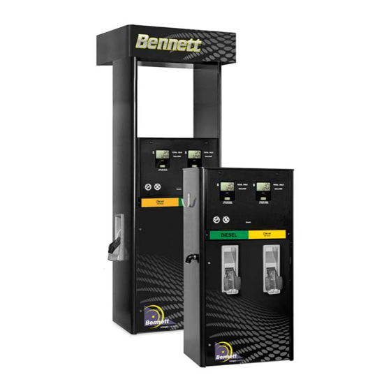
Page 4: Introduction For The 3000 Series Electronic Commercial And Retail Dispensers
Precision Bennett SB100 Meter, 4-piston, positive displacement design Hinged swing out lower door Type 75 Bennett sliding vane pumping unit with integral Hinged swing down upper door vortex air eliminator Heavy duty hose hook (optional internal spring rewind ... -
Page 5: Product Specifications
Operating Temperature Range: -30 to +50°C Humidity: 0-95% condensing DIMENSIONS 3000 Series Low Hose 60” H x 30” W x 20” D Flow Rate - Standard - 1 to 2.5 gpm (Self Contained). Motor -The hydraulic arrangement can be as follows- Suction with Standard 1 phase 115/230 v.a.c. -
Page 6: Unloading, Unpacking And Inspecting A New Dispenser
If possible, open the carton and inspect the dispenser before signing the delivery receipt. Bennett dispensers are shipped F.O.B. This means that the title to the equipment passes to the purchaser at the time the equipment is loaded on the truck at our factory. Freight damage claims are the responsibility of the purchaser. -
Page 7: Lifting A New Dispenser And Placing It On The Island
Lifting a New Dispenser and Placing it on the Island The dispenser is bolted to a pallet with bolts and nuts. With the lower doors removed and safely stored away, remove the nuts and bolts that secure the dispenser to the pallet. Remove the door and store in a safe place Unlock the lower door with the keys that until you are ready to put the door back on. -
Page 8: Anchoring The Dispenser
Anchoring the Dispenser to the Island The dispenser must be bolted firmly to the concrete island. The dispenser base is provided with anchor bolt holes (see base drawings in back of this manual for dimensions). Anchor bolts embedded in the concrete island must be not less than ½”... -
Page 9: Product Return Piping
Product Return Piping The defueler requires a product return pipe from the dispenser back to the underground storage tank. This piping carries the fuel from the vehicle to the underground tank. The dispenser is shipped with a 1” female threaded return pipe (refer to base drawing in the back of this manual). Therefore, the return piping should be [1 inch (recommended) , 3/4”... -
Page 10: Pipelines And Under Ground Containment Sumps
The dispenser must be mounted on a concrete foundation. Do not pour concrete around the product return pipe or electrical conduit. The use of a UL approved containment sump designed for the Bennett Dispenser Model used is highly recommended. Follow the containment sump manufacture’s installation instructions for proper installation. -
Page 11: Electrical Field Wiring - General Information
All dispenser field wiring between the building and the dispenser for power, neutral and ground wire conductors must not be spliced, wire nutted or shared with any other equipment. Doing so would void the Bennett Limited Warranty. All power, neutral and ground conductors shall be run from the dispenser to the Main Service Panel. -
Page 12: Piping Notes For Self Contained (Suction) Pumps
All underground conduit should be rigid metal and drawn up tight. The use of PVC (plastic) conduit is not allowed and will void the Bennett Warranty. Make sure that vapor “seal offs” are properly installed on all conduits at and from each dispenser. -
Page 13: Wiring The 3700 Series Defueler Dispenser (Electronic)
Wiring the 3700 Series Defueler Dispenser Electronic Dispenser 108670 Rev A 08/04... -
Page 14: Determining The Number Of Wires Needed
Step 4. Mechanical Pulse Output - If the dispenser is to be wired to a mechanical interface card/key system, the following wires will be needed: Note - You will need a Bennett Pulse Output Board and field wiring will be connected between this board and the third party interface system. This board will be mounted on the deck inside the electronics enclosure. -
Page 15: Pulling The Field Wires
Instructions for Earth Grounding the Equipment WARNING: Failure to properly ground the equipment can cause injury or damage to the equipment and will void the Bennett limited warranty. The dispenser must be properly grounded. Each dispenser requires a 12-gauge Green earth ground wire. -
Page 16: Ac Power Installation
50ft, 12Ga., for runs to 100ft, 10ga., for runs over 100ft and 8 ga., for runs over 250 feet. Pump motor power must be on a different phase leg than the dispenser power or system malfunction will result and the Bennett Limited Warranty will be voided. -
Page 17: Connecting Field Wiring To The Mechanical Interface Pulse Output Board
Connecting Field Wiring to the Mechanical Interface Pulse Output Board Mechanical Mode - Mechanical Mode allows the 3000 series to imitate a mechanical dispenser and interface to a mechanical pump console or control device. It also allows pulse output communication with a tank gauge. -
Page 18: Pulse Output Field Wiring Table
Pulse Output Field Wiring Table (Also refer to the Pulse Output Wiring Diagram) Wire J-Box Connection Name Color Board Connection Size (Optional) Tank Gauge Out Product A side 2 (+) Pink 18 Ga. Flying Lead Pink Product A TS1 - 7 Pulse Output Board Product A Tank Gauge Out Product A side 2 (-) Yellow 18 Ga. -
Page 19: Setting The Jumpers On The Pulse Output Board
Setting the Jumpers on the Pulse Output Board The Pulse Output board is ordered as an option with the Electronic 3000 series. This board is where the field wires connect the 3rd party Fleet System to the Pulse Output functions of the dispenser. This board also has jumpers that need to be set to determine the Pulse Rate and the Pulse Width. -
Page 20: Cpu Board Jumper Configuration
CPU Board Jumper Configuration The 3700 Series can operate in two different modes, Console or Stand Alone, which must also be defined by jumper settings on the CPU board: Stand Alone Mode -Stand Alone mode allows the 3700 Series to operate without being connected to a console or control device. - Page 21 Jumper positions 1 - 4 - (Fueling Point Address - Up to 16 fueling position addresses). Use jumper positions 1 through 4 to set the dispenser address. Normally, Bennett pumps do not need an address set when using current loop communications, but, with this RS 485 style communication, an address must be set for the 3rd party device or console to know which fueling point it is talking to.
-
Page 22: Cpu Jumper Configuration Diagram
Circuit Board Jumper Configuration Diagram Jumper Header JP1 on the CPU board is used to program the dispenser and to set the hose position address. The first 4 rows are used to set the hose position address. Addresses from 1 - 16 are available. Here is how to set the address using the first four rows of the Jumper Header. -
Page 23: Dispenser Startup And Checklist
Dispenser Startup and Checklist DANGER: Fire, explosion, injury or death will occur if fuel vapors are present. Make sure there are no vapors present before starting this procedure. CAUTION: To prevent damage to the dispenser, follow the proper start-up procedures. Before applying AC power to the dispenser, follow this procedure: 1. -
Page 24: Potting Instructions
Potting Instructions 108670 Rev A 08/04... -
Page 25: How To Mechanically Calibrate The Sb-100 Meter (M-Cal)
We strongly suggest recalibration of the meter after a 90 day break in period. With the 3000 series electronic defueler, mechanical calibration is optional. That is, the standard 3000 is calibrated electronically. That means that the meter in the dispenser that you have may not even be able to be calibrated mechanically (it will not have a mechanical calibration wheel). -
Page 26: How To Electronically Calibrate The Sb-100 Meter (E-Cal)
How to Electronically Calibrate the SB-100 Meter (E-CAL OPTION) How to set the Electronic Calibration - Electronic calibration is a simple method to calibrate the meters in the dispenser. This method uses a mathematical algorithm in the software to account for meter wear rather than mechanical methods to limit the piston throw within the meter. - Page 27 How to Electronically Calibrate the SB-100 Meter (E-CAL OPTION) Step 6 - The display should say “tc 000.0”. Enter the Test Can size that you used. See Figure. You do this using the “Up” key on the top of the board.
-
Page 28: Wiring The 3100 Series Defueler Dispenser (Mechanical)
Wiring the 3100 Series Defueler Dispenser Mechanical Dispenser 108670 Rev A 08/04... -
Page 29: General Wiring Notes
General Wiring Notes When wiring the Mechanical 3100 series defueler dispenser, the installer should follow the same practices as found in the previous section “Wiring the 37000 series Defueler - Electronic”. The main difference between the mechanical and the electronic is that the electronic has electronic boards to control the dispenser and the mechanical uses the Veeder-Root Non–... -
Page 30: Determining The Number Of Wires Needed
Determine the Number of Wires Needed (115 or 230 Volt installations) All field wires will be connected on the terminal strip in the top of the dispenser. See photo. Please refer to the Wiring Diagram for the Model 3100 1 Hose Defueler located in the Wiring Diagram section of this manual: Remove the dispenser top cover to access the wiring terminal... -
Page 31: Pulling The Field Wires
Proper Equipment Grounding WARNING: Failure to properly ground the equipment can cause injury or damage to the equipment and will void the Bennett limited warranty. The dispenser must be properly grounded. Each dispenser requires a 12-gauge Green earth ground wire. Grounding provides a path of least resistance for electric current to reduce the risk of electric shock. -
Page 32: Ac Power Installation
AC Power Installation Each dispenser uses one 115V, 50/60 Hz or 230V, 50/60 Hz circuit for dispenser electric reset power. Make sure the power source has the correct frequency and voltage. You will connect the electrical circuit to the terminal strip on the top of the dispenser underneath the cover. Only one dispenser electric reset Hot and Neutral needs to be pulled per dispenser. -
Page 33: Dispenser Startup And Checklist
Dispenser Startup and Checklist DANGER: Fire, explosion, injury or death will occur if fuel vapors are present. Make sure there are no vapors present before starting this procedure. CAUTION: To prevent damage to the dispenser, follow the proper start-up procedures. Before applying AC power to the dispenser, follow this procedure: 1. -
Page 34: Potting Instructions
Potting Instructions 108670 Rev A 08/04... -
Page 35: How To Mechanically Calibrate The Sb-100 Meter (M-Cal)
We strongly suggest recalibration of the meter after a 90 day break in period. With the 3000 series Mechanical defueler, mechanical calibration is standard. Follow these guidelines to mechanically calibrate the SB-100 meter. Each SB-100 meter is provided with the following... -
Page 36: Footprint Dimensions And Wiring Diagrams
WARNING: All doors must be replaced and locked when unit is in service. WARNING: EXPOSED BELTS AND PULLEYS. Do not operate pump with door removed except when required for maintenance and then only by a Bennett Authorized Service Representative. Keep clear of belts and pulleys. - Page 37 Footprint Dimensions and Wiring Diagrams 108670 Rev A 08/04...
- Page 38 Footprint Dimensions and Wiring Diagrams 108670 Rev A 08/04...
- Page 39 Footprint Dimensions and Wiring Diagrams 108670 Rev A 08/04...
- Page 40 Footprint Dimensions and Wiring Diagrams 108670 Rev A 08/04...
- Page 41 Footprint Dimensions and Wiring Diagrams 108670 Rev A 08/04...
- Page 42 Footprint Dimensions and Wiring Diagrams 108670 Rev A 08/04...
-
Page 43: Audit Form
(sub pumps, motors, air– conditioners etc.)? Do the supply tanks have fuel? If it is a suction system, are all suction components installed per Bennett specifications? If connected to a console, are the Interface boxes within 100 feet of the Point of Sale? - Page 44 Audit Form Exceptions to Bennett Installation Instructions—(Is there anything out of the ordinary or worth mentioning that might affect safety or dispensing equipment operation?). ________________________ ___________________________________________________________________________________ ___________________________________________________________________________________ ___________________________________________________________________________________ ___________________________________________________________________________________ ___________________________________________________________________________________ ___________________________________________________________________________________ ___________________________________________________________________________________ ___________________________________________________________________________________ ___________________________________________________________________________________ ___________________________________________________________________________________ ___________________________________________________________________________________ ___________________________________________________________________________________ ___________________________________________________________________________________ ___________________________________________________________________________________ ___________________________________________________________________________________...
-
Page 45: Warranty Statement
Bennett Pump Company warrants Bennett products and software packages, whose operation is controlled by Bennett designed and developed software, shall be free of material defects and conform to current Bennett specifications for a period of ninety (90) days from the date of original invoice. Bennett shall use its best effort to correct such defects and to supply to purchaser at Bennett’s expense, a corrected version within a reasonable time after purchaser notifies Bennett in writing of any defects and provides... - Page 46 108670 Rev A 08/04 Bennett 1218 E. Pontaluna Road, Spring Lake, MI 49456 USA 800-235-7618 ~ Outside USA 231-798-1310 sales@bennettpump.com ~ www.bennettpump.com...
Need help?
Do you have a question about the 3000 Series and is the answer not in the manual?
Questions and answers