Sign In
Upload
Manuals
Brands
Ulvac Manuals
Accessories
G-Tran IM1R1
User Manuals: Ulvac G-Tran IM1R1 4CH Display Unit
Manuals and User Guides for Ulvac G-Tran IM1R1 4CH Display Unit. We have
2
Ulvac G-Tran IM1R1 4CH Display Unit manuals available for free PDF download: Instruction Manual
Ulvac G-Tran IM1R1 Instruction Manual (84 pages)
4ch digital display unit
Brand:
Ulvac
| Category:
Monitor
| Size: 1 MB
Table of Contents
Table of Contents
7
1 Introduction
9
Overview of G-TRAN Series
9
Terminology
10
2 Features of Im1R1/Im2R1 Display Unit
11
3 Specifications and Configuration
12
Key Specifications
12
Standard Accessories
13
Options
13
Compatible Measuring Unit
14
4 Operation
15
Operation Overview
15
Operation of Components
16
Front Panel: Operation Switches
16
Front Panel: Lamp
17
Rear Panel
18
Operation
19
Setting of Display Mode
19
Operation Mode Setting CONTROL MODE
25
Baud Rate Value
27
Lcd Contrast Set
28
FIL HV On/Off Degas On/Off
29
ZERO Point/Atm Point Adjustment and Reset
31
Explanation of Operation 2 - Setting of Basic Conditions - PROGRAM MODE
32
Setting of Sensor Type MEAS. UNIT SELECT
34
Setpoint Setting
36
Setting of Combination Mode CH COMBINATION
36
Setting of Sensitivity Factor CALCULATION SET
40
HV Press. SET
42
5 External Input/Output
43
About Sensor Connector
43
Sensor Connector
43
About External IO
44
IO Connector
44
About Measurement Value Output
46
About Remote Operation
52
About Setpoint Output
53
Other Outputs
55
About Serial Communication
56
Serial Communication Setting
56
Communication Specifications
56
Communication Command
57
6 Installation
68
Preparations
68
Installing the Display Unit
68
Dimensional Drawings
70
Electrical Connection
72
Wiring in Serial Communication
73
Setting the Measuring Unit
76
About Setting of Box Unit Operation Mode
76
About Cable Connecting to Measuring Unit and Display Unit
76
7 Troubleshooting
78
Power Is Supplied, but no Display Appears
78
Pressure Has Changed, but the Segment Indicator Remains at a Certain Indication
78
Pressure Indication Is Not [FU LL] under Atmospheric Pressure
78
Pressure Has Increased, but the Segment LED Indicates
79
Pa and Does Not Change
79
After FIL (HV) Is Turned on Though FIL (HV) Lamp Is Lit
79
FIL Lamp Stays Blinking after FIL Is Turned on
79
Pressure Indication Is Not Constant
80
When the FIL/HV Is Turned ON, It Turns off Immediately or It Cannot be Turned on
80
Operation Is Disabled from Display Unit (FIL/HV ON/OFF, DEGAS ON/OFF)
80
Operation Disabled from Remote Host (FIL ON/OFF, DEGAS ON/OFF, FIL 2/1)
81
Pressure Indication Differs Greatly from Expected Value
81
NC" Is Displayed When Pirani Gauges, SP1 or BPR2 Are Connected
81
8 Warranty
82
9 Certificate of Decontamination
83
10 China Rohs Declaration
84
Advertisement
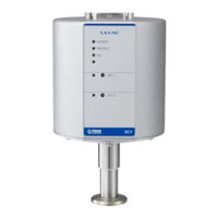
Ulvac G-Tran IM1R1 Instruction Manual (54 pages)
COLD-CATHODE ION GAUGE
Brand:
Ulvac
| Category:
Accessories
| Size: 1 MB
Table of Contents
Prior to Operation
3
Safety Denotations
3
Safety Precautions
4
Table of Contents
7
Introduction
10
Overview of G-TRAN SERIES
10
Terminology
10
FEATURES of SC1 Ion Gauge
11
Specifications and Components
12
Key Specifications
12
Standard Accessories
13
Options
13
Service Parts
13
Nomenclature and Functions of Components
14
Assembly
14
Front Panel
15
Input/Output Connector
16
Installation
17
Preparations
17
Installing the Sensor Head to the Sensor Unit
17
Installing the Sensor Unit
17
Electrical Connection
18
Cautions in Handling
19
Output Signals
20
Control Operation
20
High Voltage ON/OFF [HV ON/OFF]
20
Setpoint Actuating Signal [SET-1 ON/OFF][SET-2 ON/OFF]
20
Discharge Valid Signal [Discharge OK/NG]
20
Setting of Setpoint
21
Functions
22
Setpoint [SET-1 ON/OFF] [SET-2 ON/OFF]
22
Setpoint
22
Setting of Setpoint
22
Setpoints of Measuring Unit and Display Unit
22
Measurement Value Output
23
Measurement Value Voltage Output Form
23
Measurement Value Outputs in each Condition
24
Maintenance
25
Preparation of Tools and Others
25
Necessary Tools and Others
25
Necessary Equipment
25
Removing the Sensor Unit and Sensor Head
26
Removing Screws
26
Removing the Sensor Head
26
Disassembling the Sensor Head
27
Exploded View of Sensor Head
27
Removing the Internal Electrode
28
Cleaning the Electrode in the Sensor Head
31
Insulation Check of Anode
31
Cleaning the Anode
31
Cleaning Magnetic Poles 1 and 2
32
Cleaning the Spacer
33
Cleaning the Main Body
34
Cleaning the O-Ring and O-Ring Groove
34
Cleaning Parts
34
Reassembling the Sensor Head
35
Reassembly
35
Checking the Anode Position
35
Insulation Check
36
When a Insulation Resistance Tester Is Available at Hand
36
If a Insulation Resistance Tester Is Not Available at Hand
36
Leak Test
38
Installing the Sensor Unit and Sensor Head
39
Maintenance
39
Troubleshooting
40
Warranty
42
Certificate of Contamination
43
China Rohs Declaration
44
Appendix
45
Pressure-Measurement Value Voltage Table (Pa)
45
Pressure-Measurement Value Voltage Table (Torr)
48
Related Drawings
51
Compatible Sensor Heads
51
Advertisement
Related Products
Ulvac G-Tran ISG1
Ulvac G-Tran IM2R1
Ulvac G-Tran Series
Ulvac G-Tran SH2-1
Ulvac G-Tran SH2-2
Ulvac G-TRAN SW1-1
Ulvac G-TRAN SW1-2
Ulvac G-Tran BPR2
Ulvac G-Tran BMR2
Ulvac G-Tran SP1
Ulvac Categories
Water Pump
Air Compressor
Power Supply
Measuring Instruments
Industrial Equipment
More Ulvac Manuals
Login
Sign In
OR
Sign in with Facebook
Sign in with Google
Upload manual
Upload from disk
Upload from URL