Table of Contents
Advertisement
Quick Links
Advertisement
Table of Contents

Related Manuals for Optimum OPTIdrill B 40GSP


Summary of Contents for Optimum OPTIdrill B 40GSP
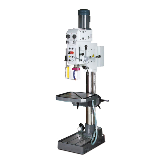
- Page 1 Operating manual Version 2.1.1 Geared drill Part no. 3034403...
-
Page 2: Table Of Contents
Table of contents Safety Rating plate...............................6 Safety instructions (warning notes)......................7 1.2.1 Classification of hazards...........................7 1.2.2 Other pictograms ............................7 Intended use .............................8 Reasonably foreseeable misuses......................8 1.4.1 Avoiding misuses............................9 Possible dangers caused by the geared drill ....................9 Qualification of personnel ........................10 1.6.1 Target group ............................10 1.6.2 Authorized persons..........................11 Operators positions..........................11 Safety measures during operation......................12... - Page 3 Installation .............................. 23 3.6.1 Fixing..............................23 3.6.2 Assembly drawing ..........................24 Cleaning of the machine......................... 24 3.7.1 Lubrication .............................. 25 3.7.2 Electrical connection ..........................25 First commissioning..........................25 3.8.1 Checks ..............................26 Coolant pump ............................26 3.10 Warming up the machine ........................26 Handling Control and indicating elements ......................
- Page 4 7.15 Bohrfutterschutz - Drilling chuck protection ....................64 7.16 Maschinenschilder - Machine labels.......................65 7.17 Schaltplan - Wiring diagram........................66 Malfunctions Appendix Liability claims for defects / warranty ......................73 Storage ..............................74 Note regarding disposal / options to reuse: ....................74 9.3.1 Decommissioning ...........................75 9.3.2 Disposal of the packaging of new devices....................75 9.3.3 Disposing of the old device........................75 9.3.4 Disposal of electrical and electronic components...................75 9.3.5 Disposal of lubricants and coolants ......................76...
- Page 5 Dear customer, Thank you very much for purchasing a product made by OPTIMUM. OPTIMUM metal working machines offer a maximum of quality, technically optimum solutions and convince by an outstanding price performance ratio. Continuous enhancements and prod- uct innovations guarantee state-of-the-art products and safety at any time.
-
Page 6: Safety
Always keep this documentation close to the geared drill. INFORMATION If you are unable to solve a problem using these operating instructions, please contact us for advice: Optimum Maschinen Germany GmbH Dr. Robert-Pfleger-Str. 26 D-96103 Hallstadt Email: info@optimum-maschinen.de Rating plate... -
Page 7: Safety Instructions (Warning Notes)
Safety instructions (warning notes) 1.2.1 Classification of hazards We classify the safety warnings into various levels. The table below gives an overview of the classification of symbols (ideogram) and the warning signs for each specific danger and its (possible) consequences. Ideogram Warning alert Definition / consequence... -
Page 8: Intended Use
If the geared drill is used in any way other than described above, modified without authoriza- tion of Optimum Maschinen Germany GmbH, then the geared drill is being used improperly. We will not be held liable for any damages resulting from any operation which is not in accord- ance with the intended use. -
Page 9: Avoiding Misuses
1.4.1 Avoiding misuses Use of suitable cutting tools. Adapting the speed adjustment and feed to the material and workpiece. Clamp workpieces firmly and vibration-free. ATTENTION! The workpiece is always to be fixed by a machine vice, jaw chuck or by another appropriate clamping tool such as for the clamping claws. -
Page 10: Qualification Of Personnel
the correct function of the geared drill may be affected. Always disconnect the geared drill if cleaning or maintenance work is being carried out. WARNING! The geared drill may only be used with the safety devices activated. Disconnect the geared drill immediately whenever you detect a failure in the safety devices or when they are not mounted! All additional devices installed by the operator have to be equipped with the prescribed safety devices. -
Page 11: 1.6.2 Authorized Persons
1.6.2 Authorized persons WARNING! Inappropriate operation and maintenance of the geared drill constitutes a danger for the staff, objects and the environment. Only authorized staff may operate the geared drill! Persons authorized to operate and maintain should be trained technical staff and instructed by the ones who are working for the operating company and for the manufacturer. -
Page 12: Safety Measures During Operation
INFORMATION The mains plug of the geared drill must be freely accessible. Safety measures during operation CAUTION! Risk due to inhaling of health hazardous dusts and mist. Dependent on the material which need to be processed and the used auxiliaries dusts and mist may be caused which might impair you health. -
Page 13: Emergency-Stop Push Button
1.9.1 EMERGENCY-STOP push button CAUTION! Also after actuating the EMERGENCY- STOP switch, the drilling spindle is EMERGENCY- turning - depending on the previously STOP button selected speed - for a few seconds more. Img.1-2: EMERGENCY-STOP button 1.9.2 Main switch The lockable main switch can be secured in position "0"... -
Page 14: 1.9.4 Drill Chuck Protection
1.9.4 Drill chuck protection Adjust the protective equipment to the correct height before you start working. Integrated position To do so, detach the clamping screw, switch adjust the required height and re-tighten the clamping screw. Clamping screw A switch is integrated in the fixture of the spindle protection which monitors that the cover is closed. -
Page 15: Individual Protection Gear
Functional check Equipment Check EMERGENCY-STOP After actuating an EMERGENCY STOP push button the geared push button drill must be switched off. Drill chuck protection The geared drill must only be switched on, if the drill chuck protection is closed. The engine must switch off when the drill chuck protection is opened during operation. -
Page 16: Safety During Maintenance
Check if they are working properly! 1.14 Accident report Inform your superiors and Optimum Maschinen Germany GmbH immediately in the event of accidents, possible sources of danger and any actions which almost led to an accident (near misses). There are many possible causes for "near misses". -
Page 17: Electrical System
1.15 Electrical system Have the machine and/or the electric equipment checked regularly. Immediately eliminate all defects such as loose connections, defective wires, etc. A second person must be present during work on live components to disconnect the power in the event of an emergency. Disconnect the lathe immediately if there is a malfunction in the power supply! Comply with the required inspection intervals in accordance with the factory safety directive, operating equipment inspection. -
Page 18: Technical Data
Technical data The following information gives the dimensions and weight and is the manufacturer‘s authorised machine data. Electrical connection Total connected load 3 x 400V; 1.5 KW Coolant pump 400V ~40W permitted voltage tolerance 380 V - 420 V Degree of protection IP 54 Drilling capacity Drilling capacity in steel [mm]... -
Page 19: Emissions
Number of steps Environmental conditions Temperature [° C] 5 - 35 rel. humidity [% 25 - 80 rel. Operating material Gear oil for spindle sleeve gear 4.5 liters Mobilgear 627 or a comparable oil Lubricant on page 69 Toothed rod and drill column commercial slide bearing grease Coolant equipment Max. -
Page 20: Dimensions
2.11 Dimensions Schwerpunkt/ Centre of grafity Img.2-1: Dimensions B40GSP B40 GSP Technical data Translation of original instruction Version 2.1.1 - 2020-07-27... -
Page 21: Delivery, Interdepartmental Transport, Assembly And Commissioning
Delivery, interdepartmental transport, assembly and commissioning Notes on transport, installation, commissioning Improper transport, installation and commissioning is liable to accidents and can cause damage or malfunctions to the machine for which we do not assume any liability or guarantee. Transport the scope of delivery secured against shifting or tilting with a sufficiently dimen- sioned industrial truck or a crane to the installation site. -
Page 22: Unpacking The Machine
Unpacking the machine Transport the drilling machine in its packing crate near its final installation location with a lift truck before unpacking it. If the packaging shows signs of possible transport damage, take the necessary precautions not to damage the machine when unpacking it. If any damage is discov- ered, the carrier and/or shipper must be notified immediately to be able to initiate the neces- sary steps for a claim. -
Page 23: Load Attachment Point In Unpacked Condition
3.5.3 Load attachment point in unpacked condition Eye bolt ø Bore hole 30-32 mm Load suspension gear Img.3-1: Example of load suspension and lifting loads Pass a piece of steel of sufficient thickness (round C 45 steel, thick-walled pipe) through the hole in the head. -
Page 24: Assembly Drawing
3.6.2 Assembly drawing Attachment (4) Img.3-3: Assembly drawing ATTENTION! Tighten the fixing screws of the geared drill only as much that it is safely fixed and cannot break away or tilt over. If the fixing screws are too tight in particular in connection with an uneven substructure it may result in a broken stand of the machine. -
Page 25: Lubrication
3.7.1 Lubrication The lubrication and initial greasing of your new machine con- sists of checking the oil sight glasses. The oil tanks must be filled to half way up the sight glass. Once these operations have been carried out, the machine can be started up. ... -
Page 26: Checks
3.8.1 Checks Check the geared drill as indicated under Safety check on page 14. Check the geared drill as indicated under Oil level of the gear of the drilling spindle sleeve on page 40. Coolant pump ATTENTION! The coolant pump also delivers if it turns in the wrong direction. -
Page 27: Handling
Handling Control and indicating elements Pos. Designation Pos. Designation Gear selector for speed increments Control panel Drill chuck protection Spindle sleeve lever Drilling table Table height adjustment Clamping lever table revolution Coolant pump Chip filter Handling B40 GSP Version 2.1.1 - 2020-07-27 Translation of original instruction... -
Page 28: Safety
Safety Use the machine only under the following conditions: The machine is in proper working order. The machine is used as prescribed. The operating manual is followed. All safety devices are installed and activated. All failures should be eliminated immediately. Stop the machine immediately in the event of any anomaly in operation and make sure it cannot be started up accidentally or without authoriza- tion Notify the person responsible immediately of any modification. - Page 29 Push button ON The push button "ON" switches on the rotation of the drilling spindle. Push button OFF The "push button OFF“ switches the rotation of the drilling spindle off. Coolant pump ON / OFF Switches the coolant pump. Machine illumination ON/OFF Switches the illumination on or off.
-
Page 30: Drill Depth Stop
Drill depth stop Adjusting screw for drill depth stop Indicator drilling depth Img.4-3: Drill depth stop Use the drilling depth stop when drilling several holes of the same depth. Loosen the adjusting screw for drill depth stop and move it until the desired drilling depth is identical to the indicator. -
Page 31: Tool Holder
Select the speed of the spindle sleeve feed actuating the selector rotary switch: - 0.10 mm / turn - 0.20 mm / turn Selector rotary switch Img.4-5: Selector rotary switch for the speed of the spindle feed INFORMATION The higher the preset number of revolutions, the greater the feed speed in the sleeve. Adjust the correct speed depending on the used material and on the drill diameter. -
Page 32: Fitting The Drill Chuck
Loosen the conical chuck from the bit-holder using a drift. Drill sleeve Drill drift Drilling spindle Drill chuck Img.4-7: Drill sleeve Disassembly with integrated drill drift ATTENTION! Hold the tool or drill chuck tight. With the below described procedure the taper mandrel is being loosened from the drilling spindle. -
Page 33: Working With The Machine
Coolant charging hole Img.4-9: Filler hole Coolant shut-off tap and doser Img.4-10: Coolant shut-off tap and doser Adjust the flow using the shut-off and dosing tap. ATTENTION! Failure of the pump in case of dry running. The pump is lubricated by the cooling agent. Do not start up the pump without cooling agent. -
Page 34: During Work
Please make sure to use a suitable dust suction when treating wood since wood dust may be health hazardous. Wear a suitable dust mask when performing works at which dust is generated. First, select the speed of the bit. This will depend on the diameter of the bit being used and ... -
Page 35: Determining The Cutting Speed And The Speed
Determining the cutting speed and the speed Table cutting speeds / infeed Material table Recommended infeed f in mm/revolution Recommended Material to be processed cutting speed Drill bit diameter d in mm Vc in m/min 2...3 >3...6 >6...12 >12...25 >25...50 Unalloyed construction steels 30 - 35 0.05... - Page 36 Drill bit Ø Speed n in rpm in mm 1062 1274 1415 1769 2123 2477 2831 3539 4246 5662 7077 1146 1274 1592 1911 2229 2548 3185 3822 5096 6369 1042 1158 1448 1737 2027 2316 2895 3474 4632 5790 1062 1327 1592...
-
Page 37: Examples To Calculatory Determine The Required Speed For Your Drilling Machine
Drill bit Ø Speed n in rpm in mm 39,0 40,0 41,0 42,0 43,0 44,0 45,0 46,0 47,0 48,0 49,0 50,0 5.2.1 Examples to calculatory determine the required speed for your drilling machine The necessary speed is depending on the diameter of the drill bit, on the material which is being machined as well as on the cutting material of the drill bit. -
Page 38: Maintenance
Maintenance In this chapter you will find important information about Inspection Maintenance Repairs ATTENTION! Properly performed regular maintenance is an essential prerequisite for operational safety, failure-free operation, long service life of the machine and ... -
Page 39: Preparation
6.1.1 Preparation WARNING! Only carry out work on the machine if it has been unplugged from the mains power supply. Disconnecting and securing the geared drill. on page 16 Attach a warning sign. 6.1.2 Restarting Before restarting run a safety check. ... - Page 40 Interval Where? What? How? Check the oil level in the inspection glass The glass oil level ( deposed ) should be half-covered. Filler hole Oil flow during operation Oil level when oil depos- ited Oil drain plug Start of shift Abb.6-2: Oil level of the gear of the drilling spindle sleeve after every...
- Page 41 Interval Where? What? How? For oil change use an appropriate collecting tray of sufficient capacity. Unscrew the screw from the drain hole. First after 200 operatingm hours, then every 2000 operating hours Img.6-4: Changing the oil in the gear of the drilling spindle sleeve Re-fill the gear with gear oil.
- Page 42 Interval Where? What? How? For oil change use an appropriate collecting tray of sufficient capacity. Unscrew the screw from the drain hole. Oil filling screw Img.6-6: Oil filling screw First after 200 operatingm Re-fills the gear of the spindle sleeve feed with gear oil. hours, then Approx.
-
Page 43: Repair
If the repairs are carried out by qualified technical personnel, they must follow the indications given in these operating instructions. Optimum Maschinen Germany GmbH accepts no liability nor does it guarantee against damage and operating malfunctions resulting from failure to observe these operating instructions. -
Page 44: Cooling Lubricants And Tanks
Cooling lubricants and tanks CAUTION! The cooling lubricant can cause diseases. Avoid direct contact with cooling lubricant or parts covered in cooling lubricant. Cooling lubricant circuits and tanks for water-cooling lubricant mixtures must be completely emptied, cleaned and disinfected as needed, but at least once per year or every time the coo- ling lubricant is replaced. -
Page 45: Inspection Plan For Water-Mixed Cooling Lubricants
6.4.1 Inspection plan for water-mixed cooling lubricants Company: No.: Date: used cooling lubricant size to be checked Inspection methods Inspection Procedure and comment intervals noticeable Appearance, odour daily Find and rectify causes, changes e.g. skim off oil, check filter, ventilate cooling lubricant system pH value Laboratory techniques... -
Page 46: Ersatzteile - Spare Parts
Ersatzteile - Spare parts Ersatzteilbestellung - Ordering spare parts Bitte geben Sie folgendes an - Please indicate the following : Seriennummer - Serial No. Maschinenbezeichnung - Machines name Herstellungsdatum - Date of manufacture Artikelnummer - Article no. Die Artikelnummer befindet sich in der Ersatzteilliste. -
Page 47: Getriebe Bohrspindel - Gear Box Main Spindel
Getriebe Bohrspindel - Gear box main spindel Abb.7-1: Getriebe Bohrspindel - Gear box main spindel B40 GSP DE | EN Version 2.1.1 - 2020-07-27 Originalbetriebsanleitung... -
Page 48: Getriebe Bohrspindel 1 Von 4 - Gear Box Main Spindel 1 Of 4
Getriebe Bohrspindel 1 von 4 - Gear box main spindel 1 of 4 Abb.7-2: Getriebe Bohrspindel 1 von 4 - Gear box main spindel 1 von 4 DE | EN B40 GSP Originalbetriebsanleitung Version 2.1.1 - 2020-07-27... -
Page 49: Getriebe Bohrspindel 2 Von 4 - Gear Box Main Spindel 2 Of 4
Getriebe Bohrspindel 2 von 4 - Gear box main spindel 2 of 4 Abb.7-3: Getriebe Bohrspindel 2 von 4 - Gear box main spindel 2 von 4 B40 GSP DE | EN Version 2.1.1 - 2020-07-27 Originalbetriebsanleitung... -
Page 50: Getriebe Bohrspindel 3 Von 4 - Gear Box Main Spindel 3 Of 4
Getriebe Bohrspindel 3 von 4 - Gear box main spindel 3 of 4 Abb.7-4: Getriebe Bohrspindel 3 von 4 - Gear box main spindel 3 von 4 DE | EN B40 GSP Originalbetriebsanleitung Version 2.1.1 - 2020-07-27... -
Page 51: Getriebe Bohrspindel 4 Von 4 - Gear Box Main Spindel 4 Of 4
Getriebe Bohrspindel 4 von 4 - Gear box main spindel 4 of 4 Abb.7-5: Getriebe Bohrspindel 4 von 4 - Gear box main spindel 4 von 4 B40 GSP DE | EN Version 2.1.1 - 2020-07-27 Originalbetriebsanleitung... - Page 52 B40 GSP - Ersatzteilliste Getriebe Bohrspindel - Spare part list gear box main spindel Menge Größe Artikelnummer Bezeichnung Designation Qty. Size Item no. Getriebegehäuse Gear housing 03334403180CPL Motor Motor 03334400171 Scheibe Washer DIN 125 - A 10,5 Innensechskantschraube Socket head screw GB 70-85 - M10 x 35 Flachdichtung Gasket...
- Page 53 Zahnrad Gear 03334403228 Zahnrad Gear 03334400216 Zahnrad Gear 03334400217 Sicherungsring Retaining ring DIN 471 - 60x2 042SR60W Deckel Cover Sicherungsring Retaining ring DIN 472 - 68 x 2,5 042SR68I Deckel Cover DIN 3771 - 58 x 3,55 - O-Ring O-Ring 03334400223 N - NBR 70 Sicherungsring...
-
Page 54: Vorschubgetriebe - Feed Gear Box
Vorschubgetriebe - Feed gear box Abb.7-6: Vorschubgetriebe - Feed gear box DE | EN B40 GSP Originalbetriebsanleitung Version 2.1.1 - 2020-07-27... -
Page 55: Vorschubgetriebe 1 Von 4 - Feed Gear Box 1 Of 4
7.10 Vorschubgetriebe 1 von 4 - Feed gear box 1 of 4 Abb.7-7: Vorschubgetriebe 1 von 4 - Feed gear box 1 of 4 B40 GSP DE | EN Version 2.1.1 - 2020-07-27 Originalbetriebsanleitung... -
Page 56: Vorschubgetriebe 2 Von 4 - Feed Gear Box 2 Of 4
7.11 Vorschubgetriebe 2 von 4 - Feed gear box 2 of 4 Abb.7-8: Vorschubgetriebe 2 von 4 - Feed gear box 2 of 4 DE | EN B40 GSP Originalbetriebsanleitung Version 2.1.1 - 2020-07-27... -
Page 57: Vorschubgetriebe 3 Von 4 - Feed Gear Box 3 Of 4
7.12 Vorschubgetriebe 3 von 4 - Feed gear box 3 of 4 Abb.7-9: Vorschubgetriebe 3 von 4 - Feed gear box 3 of 4 B40 GSP DE | EN Version 2.1.1 - 2020-07-27 Originalbetriebsanleitung... -
Page 58: Vorschubgetriebe 4 Von 4 - Feed Gear Box 4 Of 4
7.13 Vorschubgetriebe 4 von 4 - Feed gear box 4 of 4 Abb.7-10: Vorschubgetriebe 4 von 4 - Feed gear box 4 of 4 DE | EN B40 GSP Originalbetriebsanleitung Version 2.1.1 - 2020-07-27... - Page 59 B40 GSP - Ersatzteilliste Vorschubgetriebe - Spare part list feed gear box Menge Größe Artikelnummer Bezeichnung Designation Qty. Size Item no. Zylinderstift Straight pin ISO 8734 - 6 x 45 - A 0333440042 Rückholfeder Return spring 0333440043 Rückholfeder Return spring 0333440043A Zahnrad Gear...
- Page 60 Stahlkugel Steel ball 042KU06 Feder Spring 0,8x7x12 0333440091 Sperrbolzen Lockbolt 0333440092 Sperrbolzen Lockbolt 0333440092A 92-1 Gehäuse Housing 0333440921 92-2 Innensechskantschraube Socket head screw GB 70-85/M6x20 Platte Plate 0333440096 Innensechskantschraube GB 70-85 - M6 x 20 Innensechskantschraube Socket head screw GB 70-85 - M5 x 8 Platte Plate Zeiger...
- Page 61 DIN 6885 - A 6 x 6 x Passfeder Fitting key 042P6614 Zahnrad Gear 03334400145 Sicherungsring Retaining ring DIN 471 - 15x1 042SR15W Kugellager Ball bearing 6002-2Z 0406002ZZ Sicherungsring Retaining ring DIN 472 - 32x1,2 042SR32W Getriebeschnecke Worm gear 03334400151 Nadellager Needle bearing HK 2520...
-
Page 62: Säule Und Bohrtisch - Column And Drilling Table
7.14 Säule und Bohrtisch - Column and drilling table Abb.7-11: Säule und Bohrtisch - Column and drilling table DE | EN B40 GSP Originalbetriebsanleitung Version 2.1.1 - 2020-07-27... - Page 63 B40 GSP - Ersatzteilliste Säule und Bohrtisch - Spare part list column and drilling table Menge Größe Artikelnummer Bezeichnung Designation Qty. Size Item no. Maschinenfuß Machine base 0333440001 Befestigungsplatte Plate 0333440002 Innensechskantschrauben Hexagon socket screws GB 70-85 - M6 x 12 Kühlmittelpumpe Coolant pump 0333440004...
-
Page 64: Bohrfutterschutz - Drilling Chuck Protection
7.15 Bohrfutterschutz - Drilling chuck protection Abb.7-12: Bohrfutterschutz - Drilling chuck protection B40 GSP - Ersatzteilliste Bohrfutterschutz- Spare part list drilling chuck protection Menge Größe Artikelnummer Bezeichnung Designation Qty. Size Item no. Innensechskantschraube Socket head screw GB 70-85 - M6 x 10 Scheibe Washer Innensechskantschraube... -
Page 65: Maschinenschilder - Machine Labels
Platte Plate 030031712019 Alu- Profil Aluminium profile 0302130381 Bohrfutterschutz kpl. Drill chuck protection cpl. 03334403170 Schraube Screw GB819-85/M5x8 7.16 Maschinenschilder - Machine labels Abb.7-13: Maschinenschilder - Machine labels B40 GSP - Maschinenschilder - Machine labels Menge Grösse Artikelnummer Bezeichnung Designation Quantity Size Article no. -
Page 66: Schaltplan - Wiring Diagram
7.17 Schaltplan - Wiring diagram Abb.7-14: Schaltplan - Wiring diagram DE | EN B40 GSP Originalbetriebsanleitung Version 2.1.1 - 2020-07-27... - Page 67 B40 GSP - Ersatzteilliste Elektrik- Spare part list electric Menge Größe Artikelnummer Pos. Bezeichnung Designation Qty. Size Item no. NOT-Halt Schalter Emergency stop button KPMT3-10R 03334400SB0 Drucktaster "Aus" Button "off" CP1-10Y-01 0460001 Schalter "Ein" Button "on" KB1-11G 03334403SB1 Schalter Bohrfutterschutz Drilling chuck safety switch Schalter Maschinenbeleuchtung Switch machine light...
- Page 68 DE | EN B40 GSP Originalbetriebsanleitung Version 2.1.1 - 2020-07-27...
- Page 69 oil-compare-list.fm Viskosität Schmierstoffe Viskosity Kennzeich- Lubricant nung nach Viscosité ISO VG DIN 51502 Lubrifiant DIN 51519 mm²/s (cSt) Aral Degol BG BP Energol SPARTAN Klüberoil Mobilgear Shell Omala VG 680 CLP 680 Meropa 680 GR-XP 680 EP 680 GEM 1-680 Aral Degol BG BP Energol SPARTAN...
- Page 70 Techno Service GmbH ; Detmolder Strasse 515 ; D-33605 Bielefeld ; (++49) 0521- 924440 ; www.metaflux-ts.de haute vitesse Schneidöl Aquacut C1, 10 L Gebinde, Artikel Nr. 3530030 Kühlschmiermittel EG Sicherheitsdatenblatt Cooling lubricants Chevron Aral Emusol BP Sevora Esso Kutwell Mobilcut Shell Adrana http://www.optimum-daten.de/ Soluble Oil B Lubrifiants de refroidisse- data-sheets/Optimum-Aqua- ment cut_C1-EC-datas- heet_3530030_DE.pdf oil-compare-list.fm...
-
Page 71: Malfunctions
Malfunctions Malfunction Cause / possible effects Solution Noise during work. • Spindle is too little lubricated • Grease spindle • Tool is blunt or wrongly clamped • Use new tool and check securing (fixed setting of the bit, bit holder and chuck). - Page 72 Malfunction Cause / possible effects Solution Working spindle rattling on • Excessive slack in bearing • Readjust bearing slack or replace rough piece surfaces bearing • Working spindle moves up and down • Readjust bearing clearance (fixed • Adjustment strip loose bearing) •...
-
Page 73: Appendix
- Non reproducible software errors Any services which OPTIMUM GmbH or one of its agents performs in order to fulfill in the frame of an additional guarantee are neither an acceptance of the defects nor an accept- ance of its obligation to compensate. Such services do neither delay nor interrupt the war- ranty period. -
Page 74: Storage
Example:not stackable - do not stack a second packing case on top of the first packaging case Consult Optimum Maschinen Germany GmbH if the machine and accessories are stored for more than three months or are stored under different environmental conditions than those given here. -
Page 75: 9.3.1 Decommissioning
9.3.1 Decommissioning CAUTION! Immediately decommission used machines in order to avoid later misuse and endangering of the environment or of persons. Dsconnect the plug from the power supply. Cut the connection cable. Remove all environmentally hazardous operating fluids from the used device. ... -
Page 76: 9.3.5 Disposal Of Lubricants And Coolants
Modified settings Any experiences with the geared drill which might be important for other users Recurring failures Optimum Maschinen Germany GmbH Dr.-Robert-Pfleger-Str. 26 D-96103 Hallstadt Fax +49 (0) 951 - 96 555 - 888 Email: info@optimum-maschinen.de B40 GSP... - Page 77 EC - Declaration of Conformity according to Machinery directive 2006/42/EC, Annex II 1.A The manufacturer / distributor Optimum Maschinen Germany GmbH Dr.-Robert-Pfleger-Str. 26 D - 96103 Hallstadt, Germany hereby declares that the following product Product designation: Drilling machine Type designation:...
- Page 78 Index Specialist dealer ...........43 Speeds ..............18 Accident report ............. 16 Spindle seat ............18 Storage and packaging .........22 Classification of hazards ........7 Customer service ..........43 Table cutting speeds ..........35 Customer service technician ........ 43 Technical data drilling capacity ..........18 Disinfection drilling table ............18 Cooling lubricant tank ........
- Page 79 Quellenverzeichnis von Ihrem Fachhändler Metallbau Mehner Optimum Bohrmaschinen: OPTIdrill B 40GSP • ◦ OPTIdrill B 40GSP Ersatzteile ◦ OPTIdrill B 40GSP Zubehör OPTIdrill Zubehör • Ihr Ersatzteil nicht in den Listen? Direkt zum >>Formular Download<<. Tragen sie Ihr Maschinenmodell, samt Bauteil und Artikelnr.
Need help?
Do you have a question about the OPTIdrill B 40GSP and is the answer not in the manual?
Questions and answers