Optimum Optidrill B 24H Operating Manual
Bench drilling machine
Hide thumbs
Also See for Optidrill B 24H:
- Operating manual (80 pages) ,
- Operating manual (100 pages) ,
- Operating manual (176 pages)

Related Manuals for Optimum Optidrill B 24H


Summary of Contents for Optimum Optidrill B 24H
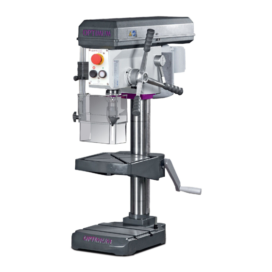
- Page 1 Operating Manual Version 2.2.6 Bench drilling machine Part no. 3020241 3020243 Part no. 3020245 Upright drilling machine Part no. 3020283 Part no. 3020285...
-
Page 2: Table Of Contents
Table of contents Safety Safety instructions (warning notes)........................ 6 1.1.1 Classification of hazards ........................6 1.1.2 Other pictograms..........................7 Intended use ..............................8 Reasonably foreseeable misuse........................9 1.3.1 Avoiding misuse ..........................10 Possible dangers caused by the drilling machine..................10 Qualification of personnel .......................... - Page 3 3.6.1 Electrical connection........................35 3.6.2 Warming up the machine ........................36 Operation Safety ................................37 Control and indicating elements ........................37 4.2.1 Drilling machine B24H - B24HV......................37 4.2.2 Drilling machine B28H - B28HV......................38 4.2.3 Control panel B24H - B24HV......................39 4.2.4 Control panel B28H - B28HV......................39 Switching the machine B24H - B28H on ......................41 Switching the machine B24HV - B28HV on ....................41 Switching the machine B24H - B28H off ......................41...
- Page 4 7.10.4 Ersatzteilliste B28H - Parts list B28H ..................... 84 7.11 Ersatzteilzeichnung B28HV - Spare parts drawing B28HV ................. 88 7.11.1 Bohrkopf B28HV - Drilling head B28HV..................88 7.11.2 Säule und Bohrtisch B28HV - Column and drilling table B28HV ........... 89 7.11.3 Keilriemenscheiben B28HV - Pulleys B28HV ................
- Page 5 Dear customer, Thank you very much for purchasing a product made by OPTIMUM. OPTIMUM metal working machines offer a maximum of quality, technically optimum solutions and convince by an outstanding price performance ratio. Continuous enhancements and product innovations guarantee state-of-the-art products and safety at any time.
-
Page 6: Safety
Always keep this documentation close to the drilling machine. INFORMATION If you are unable to rectify an issue using these operating instructions, please contact us for advice: Optimum Maschinen Germany GmbH Dr. Robert-Pfleger-Str. 26 D-96103 Hallstadt, Germany Email: info@optimum-maschinen.de Safety instructions (warning notes) 1.1.1... -
Page 7: Other Pictograms
Symbol Alarm expression Definition / consequence Practical tips and other important or useful information and notes. No dangerous or harmful consequences for people or objects. Information In case of specific dangers, we replace the pictogram with general danger with a warning of injury to hands, hazardous rotating parts. -
Page 8: Intended Use
If the drilling machine is used in any way other than described above, modified without authori- zation of Optimum Maschinen Germany GmbH, then the geared drill is being used improperly. We will not be held liable for any damages resulting from any operation which is not in accor- dance with the intended use. -
Page 9: Reasonably Foreseeable Misuse
Reasonably foreseeable misuse Any use other than that specified under "Intended use" or any use beyond that described will be deemed non-intended use and is not permissible. Any other use must be discussed with the manufacturer. It is only allowed to process metal, cold and non-inflammable materials with the drilling machine. -
Page 10: Avoiding Misuse
1.3.1 Avoiding misuse Use of suitable cutting tools. Adapting the speed adjustment and feed to the material and workpiece. Clamp workpieces firmly and free of vibration. Operating the drilling machineB24HV and B28HV only in industrial supply networks. ATTENTION! The workpiece is always to be fixed by a machine vice, jaw chuck or by another appropriate clamping tool such as for the clamping claws. -
Page 11: Qualification Of Personnel
there may be a risk to the machine and other material values, the correct function of the drilling machine may be affected. Always disconnect the drilling machine if cleaning or maintenance work is being carried out, or is no longer in use. WARNING! The drilling machine may only be operated with functional safety devices. -
Page 12: Authorized Persons
1.5.2 Authorized persons WARNING! Inappropriate operation and maintenance of the drilling machine constitutes a danger for the personnel, objects and the environment. Only authorized personnel may operate the drilling machine ! Authorized operating and maintenance personnel are specialists instructed and trained by the operator company and the manufacturer. -
Page 13: Operator Positions
Operator positions The operator position is in front of the drilling machine. Abb.1-1: Operator positions Safety measures during operation CAUTION! Danger due to inhaling dust and mist that are hazardous to health. Depending on the materials to be machined and the agents used, dusts and mists can arise that are detrimental to health. -
Page 14: Safety Check
aking off, they cannot eliminate these risks completely. Always work carefully and observe the limits of the machining process. The drilling machine features the following safety devices: an emergency stop push button, a drilling table with T-slots to fix the workpiece or a vice, ... -
Page 15: Emergency-Stop Push Button
1.10 Emergency-stop push button ATTENTION! The drilling spindle keeps turning for a short time even after actuating the emergency stop push but- ton depending on the pre- set speed. Emergency- stop push button Abb.1-2: Emergency stop B24H - B24HV, B28H - B28HV 1.11 Drilling table Seats for T-slots are atta-... -
Page 16: Drill Chuck Guard
1.12.2 Drill chuck guard Adjust the guard to the correct height before you start working. To do so, slacken the clamping screw, set the required height and re- Clamping screw tighten the clamping screw. There is a switch integrated in the spindle protection mounting which monitors the closed position. -
Page 17: Safety During Maintenance
no objects are damaged. Avoid any unsafe work methods: Make sure that your operation does not create a safety hazard. The rules specified in these operating instructions must be observed during assembly, ope- ration, maintenance and repair. Do not work on the drilling machine if your concentration is reduced, for example, because ... -
Page 18: Accident Report
1.17 Accident report Inform your supervisors and Optimum Maschinen Germany GmbH immediately in the event of accidents, possible sources of danger and any actions which almost led to an accident (near misses). There are many possible causes for "near misses". -
Page 19: Technical Specification
Technical specification The following information represents the dimensions and indications of weight and the manu- facturer‘s approved machine data. Electrical connection B24H B28H 230V ~50 Hz 850 W 400V ~50 Hz 400V ~50 Hz 850 W 850 W Connection B24HV B28HV 230V ~50 Hz 230V ~50 Hz... -
Page 20: Emissions
Required space B24H - B24HV B28H - B28HV Depth [mm] 1700 1800 Width [mm] 1500 1600 Weight [kg] 92 - 96 Speeds type H B24H B28H Spindle speeds [ min 350 - 4000 120 - 4000 Number of stages Speeds type HV B24HV B28HV Spindle speeds [ min... - Page 21 Characteristics of the working area, e.g. size of damping behaviour, other noise sources, e.g. the number of machines, other processes taking place in proximity and the period of time, during which the operator is exposed to the noise. Furthermore, it is possible that the admissible exposure level might be different from country to country due to national regulations.
-
Page 22: Dimensions B24H
2.11 Dimensions B24H Abb.2-1: Dimensions B24H Technical specification B24H | B24HV | B28H | B28HV Translation of the original instructions Version 2.2.6 - 2020-07-21... -
Page 23: Dimensions B24Hv
2.12 Dimensions B24HV Abb.2-2: Dimensions B24HV Technical specification B24H | B24HV | B28H | B28HV Version 2.2.6 - 2020-07-21 Translation of the original instructions... -
Page 24: Dimensions B28H
2.13 Dimensions B28H Abb.2-3: Dimensions B28H Technical specification B24H | B24HV | B28H | B28HV Translation of the original instructions Version 2.2.6 - 2020-07-21... -
Page 25: Dimensions B28Hv
2.14 Dimensions B28HV Abb.2-4: Dimensions B28HV Technical specification B24H | B24HV | B28H | B28HV Version 2.2.6 - 2020-07-21 Translation of the original instructions... -
Page 26: Delivery, Interdepartmental Transport And Unpacking
Delivery, interdepartmental transport and unpacking CAUTION! Injuries caused by parts falling over or off a forklift, pallet truck or transport vehicle. Only use means of transport that can carry the total weight and are suitable for it. Notes on transport, installation and unpacking Improper transport of individual devices and minor machines, unsecured devices and minor machines stacked on top of each other or next to each other in packed or already unpacked condition is accident-prone and can cause damage or malfunctions for which we do not grant... -
Page 27: Scope Of Delivery
Scope of delivery When the machine is delivered, please check immediately that it has not been damaged during transport. Compare the scope of delivery with the attached packing list. Set-up and assembly 3.3.1 Requirements regarding the installation site Organize the working area around the drilling machine according to the local safety regulations. INFORMATION In order to attain good functionality and a high processing accuracy as well as a long service life of the machine, the place of installation should fulfil certain criteria. -
Page 28: Mounting Of Base And Drill Column
3.4.1 Mounting of base and drill column INFORMATION For the mounting of the drilling machine you need a wrench and the hexagon screws which are included in the delivery volume. Put the stand on the floor and fix the drill Drilling column column to the stand. -
Page 29: Assembly Of The Drilling Machine Table B24H - B24Hv
3.4.2 Assembly of the drilling machine table B24H - B24HV Push the toothed rack into the drilling table. Adjust the toothed rack within the drilling machine table in a way that the teeth of the Drilling table toothed rack cam into the spiral wheel of the support for the drilling machine table. - Page 30 Mount the coolant system. Mount all cooling agent hoses and Drilling table fasten you these with the hose clamps. Coolant system Drilling column Cooling agent hoses Abb.3-4: Assembly of coolant system INFORMATION The longer side of the too- thed rack without toothing Guide ring must be upside.
-
Page 31: Fitting The Drill Head
Mount the crank handle for the height-adjustment of the drilling table. Clamp the crank handle with the hexagon socket screw. Hexagon socket screw Crank handle Abb.3-6: Assembly crank handle 3.4.4 Fitting the drill head Put the intermediate plate on the drilling column. ... -
Page 32: Installation
Installation Check that the drilling machine foundation is horizontal with a spirit level. Check that the foundation has sufficient load-bearing capacity and rigidity. Place the drilling machine on the provided foundation. Fix the drilling machine base to the substructure through the holes pre-drilled for this pur- pose. -
Page 33: Installation Drawings
Abb.3-10: Attachment to the base ATTENTION! Tighten the fixing screws of the drilling machine only as much that it is safely fixed and cannot break away or tilt over. If the fixing screws are too tight in particular in connection with an uneven substructure it may result in a broken stand of the machine. - Page 34 B28H Attachment (2) Abb.3-12: B28H B28H - B28HV Attachment (3) Abb.3-13: B28H - B28HV B24H | B24HV | B28H | B28HV Translation of the original instructions Version 2.2.6 - 2020-07-21...
-
Page 35: First Commissioning
OPTIMUM. Only use tool holders in the intended admissible speed range. Tool holders may only be modified in compliance with the recommendation of OPTIMUM or of the manufacturer of the clamping devices. WARNING! There is a danger to persons and equipment, if the first commissioning of the drilling machine is carried out by inexperienced personnel. -
Page 36: Warming Up The Machine
3.6.2 Warming up the machine ATTENTION! If the drilling machine and in particular the drilling spindle is immediately operated at maximum load when it is cold it may result in damages. If the machine is cold, e.g. directly after having transported the machine, it should be warmed up at a spindle speed of only 500 1/min for the first 30 minutes. -
Page 37: Operation
Operation Safety Commission the machine only under the following conditions: The machine is in proper working order. The machine is used as prescribed. Follow the operating instructions. All safety devices are installed and activated. All failures should be eliminated immediately. Stop the machine immediately in the event of any anomaly in operation and make sure it cannot be started up accidentally or without authoriza- tion Notify the person responsible immediately of any modification. -
Page 38: Drilling Machine B28H - B28Hv
4.2.2 Drilling machine B28H - B28HV Img.4-2: B28H B28HV Pos. Designation Pos. Designation Belt drive with housing Lever for spindle sleeve feed Emergency stop On , Off Drill chuck Drilling table Table height adjustment Lever for belt tension Coolant device B28HV Chip filter B28HV Operation B24H | B24HV | B28H | B28HV... -
Page 39: Control Panel B24H - B24Hv
4.2.3 Control panel B24H - B24HV Machine illumination ON / OFF Emergency-stop push button Selector switch rotational direc- tion Left hand motion/ clockwise rotation Push button "ON" Push button "OFF" Img.4-3: Operating elements on the control panel B24H Rev counter Machine illumination On / Off Potentiometer... - Page 40 Machine illumination ON / OFF Rev counter Coolant pump ON / OFF Potentiometer Selector switch rotational direc- tion Left hand motion/ clockwise rotation Push button "ON" Emergency-stop push button Img.4-6: Operating elements on the control panel B28HV Selector switch rotational direction Operation mode for selection of right-handed or left-handed rotation.
-
Page 41: Switching The Machine B24H - B28H On
Switching the machine B24H - B28H on Switch on the master switch. Select the direction of rotation. Actuate the push button "ON". Switching the machine B24HV - B28HV on Switch on the master switch. Select the direction of rotation. ... -
Page 42: Switching The Machine B24Hv - B28Hv Off
Switching the machine B24HV - B28HV off CAUTION! Only press the emergency-stop button in a genuine emergency. You should not use the emergency-stop button to stop the machine during normal operation. Actuate the push button "OFF". For a long-term standstill of the machine switch it off at the main switch. Speed variation WARNING! Danger due to drill chuck or tools flying off at high speed. -
Page 43: Speed Table B24H
4.7.1 Speed table B24H Img.4-10: Speed table B24H 4.7.2 Speed table B24HV Img.4-11: Speed table B24HV Operation B24H | B24HV | B28H | B28HV Version 2.2.6 - 2020-07-21 Translation of the original instructions... -
Page 44: Speed Table B28H
4.7.3 Speed table B28H Img.4-12: Speed table B28H Operation B24H | B24HV | B28H | B28HV Translation of the original instructions Version 2.2.6 - 2020-07-21... -
Page 45: Speed Table B28Hv
4.7.4 Speed table B28HV Img.4-13: Speed table B28HV Drill depth stop Use the drilling depth stop when drilling several holes Scale of the same depth. Loosen the locking screw and turn the graduated collar until the required drilling depth matches with the indicator. -
Page 46: Disassembly, Assembly Of Drill Chucks And Drill Bits
Disassembly, assembly of drill chucks and drill bits 4.9.1 Use of the quick-action drill chuck The drill chuck consists of two parts (1 and 2). Hold the upper part (No.1) of the drill chuck. With the bottom part of the drill chuck (No. -
Page 47: Disassembly With The Integrated Drill Drift On The B28H - B28Hv
4.9.3 Disassembly with the integrated drill drift on the B28H - B28HV ATTENTION! The tool and/or the drill chuck will fall down. Hold the tool or the drill chuck while drifting it out. ATTENTION! Do not try to expel the tool when it is in the intermediate position. -
Page 48: Mounting The Drill Chuck B24H - B24Hv And B28H - B28Hv
4.9.4 Mounting the drill chuck B24H - B24HV and B28H - B28HV The drill chuck or the tool is secured in the drill spindle against turning over by means of a form- Drill sleeve locking connection (driver). frictionally engaged connection keeps and cen- tres the drill chuck or the Driver drill in the drill spindle. -
Page 49: Before Starting Work
ATTENTION! Destruction of the pump due dry running. The pump is lubricated by the cooling agent. Do not operate the pump without coolant. CAUTION! Danger of injury due to brushes getting caught or pulled in. Use a spray gun or a washing bottle for cooling. INFORMATION Use a water-soluble and non-pollutant emulsion as a cooling agent.This can be acquired from authorised distributors. - Page 50 INFORMATION The smaller the bit the more easily it may break. In the case of deep drilling, remove the bit from time to time to remove filings from the drill. Add a few drops of oil to reduce friction and prolong the service life of the bit. Operation B24H | B24HV | B28H | B28HV Translation of the original instructions...
-
Page 51: Determining The Cutting Speed And The Speed
Determining the cutting speed and the speed Table cutting speeds / infeed Material table Recommended infeed f in mm/revolution Recommended cutting speed Material to be processed Drill bit diameter d in mm Vc in m/min 2...3 >3...6 >6...12 >12...25 >25...50 Unalloyed construction steels 30 - 35 0.05... - Page 52 Drill bit Speed n in rpm Ø in mm 1062 1274 1415 1769 2123 2477 2831 3539 4246 5662 7077 1146 1274 1592 1911 2229 2548 3185 3822 5096 6369 1042 1158 1448 1737 2027 2316 2895 3474 4632 5790 1062 1327 1592...
-
Page 53: Examples To Calculatory Determine The Required Speed For Your Drilling Machine
Drill bit Speed n in rpm Ø in mm 39,0 40,0 41,0 42,0 43,0 44,0 45,0 46,0 47,0 48,0 49,0 50,0 Examples to calculatory determine the required speed for your drilling machine The necessary speed is depending on the diameter of the drill bit, on the material which is being machined as well as on the cutting material of the drill bit. -
Page 54: Maintenance
Maintenance In this chapter you will find important information about Inspection, Maintenance and Repair. ATTENTION! Properly performed regular maintenance is an essential prerequisite for operational safety, failure-free operation, long service life of the machine and ... -
Page 55: Inspection And Maintenance
WARNING! Before starting the machine you must be sure that no dangers generated for persons, the machine is not damaged. Inspection and maintenance The type and level of wear depends to a large extent on the individual usage and operating conditions. - Page 56 Interval Where? What? How? Check whether the V-belts have become porous and worn. V-belt B24H - B24HV Every 6 months V-belt B28H - B28HV Abb.6-2: V-belt housing Lubricate all oiler cups with machine oil, do not use grease guns or the like.
- Page 57 Interval Where? What? How? Cooling lubricants and tanks on page 60 Coolant pump: The coolant pump is almost maintenance free. Replace the cooling agent regularly, depending on usage. When using coolants which are leaving remnants it is necessary to rinse the cooling pump.
- Page 58 Interval Where? What? How? Any unusual rattling noises can be eliminated by regreasing. The sleeve (1) moves downwards or upwards with the toothed spindle (2) in the fixed driven sleeve (3) during drill feed. The noises are caused by the necessary clearance between the two toothings of the sleeve and spindle.
- Page 59 Interval Where? What? How? CAUTION! Parts can be thrown towards you. When disassem- bling the key housing, please make sure that the machine is only maintained and prepared by quali- fied staff. Spring barrel Circlip according to demand. Abb.6-6: Spindle return spring Spiral spring Spring barrel Abb.6-7:...
-
Page 60: Repair
If the repairs are carried out by qualified technical personnel, they must follow the indications given in these operating instructions. Optimum Maschinen Germany GmbH accepts no liability nor does it guarantee against damage and operating malfunctions resulting from failure to observe these operating instructions. -
Page 61: Cooling Lubricants And Tanks
Cooling lubricants and tanks CAUTION! The cooling lubricant can cause diseases. Avoid direct contact with cooling lubricant or parts covered in cooling lubricant. Cooling lubricant circuits and tanks for water-cooling lubricant mixtures must be completely emptied, cleaned and disinfected as needed, but at least once per year or every time the coo- ling lubricant is replaced. -
Page 62: Inspection Plan For Water-Mixed Cooling Lubricants
6.4.1 Inspection plan for water-mixed cooling lubricants Company: No.: Date: used cooling lubricant size to be checked Inspection methods Inspection Procedure and comment intervals noticeable Appearance, odour daily Find and rectify causes, changes e.g. skim off oil, check filter, ventilate cooling lubricant system pH value Laboratory techniques... -
Page 63: Ersatzteile - Spare Parts
Ersatzteile - Spare parts Ersatzteilbestellung - Ordering spare parts Bitte geben Sie folgendes an - Please indicate the following : Seriennummer - Serial No. Maschinenbezeichnung - Machines name Herstellungsdatum - Date of manufacture Artikelnummer - Article no. ... -
Page 64: Ersatzteilzeichnung B24H - Spare Parts Drawing B24H
Ersatzteilzeichnung B24H - Spare parts drawing B24H 7.4.1 Bohrkopf B24H - Drilling head B24H Abb.7-1: Bohrkopf B24H - Drilling head B24H DE │GB B24H | B24HV | B28H | B28HV Originalbetriebsanleitung Version 2.2.6 - 2020-07-21... -
Page 65: Säule Und Bohrtisch B24H - Column And Drilling Table B24H
7.4.2 Säule und Bohrtisch B24H - Column and drilling table B24H 71-1 83-1 11-1 78-1 10-2 10-1 Abb.7-2: Säule und Bohrtisch B24H - Column and drilling table B24H B24H | B24HV | B28H | B28HV DE │GB Version 2.2.6 - 2020-07-21 Originalbetriebsanleitung... -
Page 66: Keilriemenscheiben B24H - Pulleys B24H
7.4.3 Keilriemenscheiben B24H - Pulleys B24H 29-1 95-2 95-1 31-1 36-1 30-1 30-2 30-3 29-1 Abb.7-3: Keilriemenscheiben B24H - Pulleys B24H DE │GB B24H | B24HV | B28H | B28HV Originalbetriebsanleitung Version 2.2.6 - 2020-07-21... - Page 67 Ersatzteilliste B24H - Parts list B24 B24H Menge Grösse Artikelnummer Pos. Bezeichnung Designation Qty. Size Item no. Standfuss Base 030202411 Bohrsäule Column Ø80mm 030202412 Zahnstange Toothed rack L:525mm 030202413 Zahnrad Toothed wheel 030202414 Antriebsschnecke Drive screw 030202415 Distanzscheibe Spacer Spindel Spindle 030202417 Keilriemen...
- Page 68 Riemenscheibe Pulley 0302024138 Innensechskantschraube Socket head screw M6x15 Halteplatte Holder plate 0302024140 Motorplatte Engine plate 0302024141 Bohrkopf Drilling head 0302024142 42-1 Scheibe Washer 42-2 Platte Plate 03020241422 42-3 Innensechskantschraube Socket head screw M6x12 42-4 Buchse Bushing Distanzring Spacer ring 0302024143 Kugellager Ball bearing 6005...
- Page 69 95-2 Innensechskantschraube Socket head screw M6x12 96-1 Sicherungsring Circlip Kabelentlastung Cable discharge Deckel Cover 03020245240 Schaltkasten Switch box 03020245241 Kabelentlastung Cable discharge Hauptschalter Main switch 0302024187 Sicherungsgehäuse Fuse housing Sicherung Fuse Sicherung Fuse Lüfterrad Fan wheel Motordeckel Motor cover Rändelschraube Knurled screw Gleitlager Plain bearing...
-
Page 70: Ersatzteilzeichnung B24Hv - Spare Parts Drawing B24Hv
Ersatzteilzeichnung B24HV - Spare parts drawing B24HV 7.5.1 Bohrkopf B24HV - Drilling head B24HV Abb.7-4: Bohrkopf B24HV - Drilling head B24HV DE │GB B24H | B24HV | B28H | B28HV Originalbetriebsanleitung Version 2.2.6 - 2020-07-21... -
Page 71: Säule Und Bohrtisch B24Hv - Column And Drilling Table B24Hv
7.5.2 Säule und Bohrtisch B24HV - Column and drilling table B24HV Abb.7-5: Säule und Bohrtisch B24HV - Column and drilling table B24HV B24H | B24HV | B28H | B28HV DE │GB Version 2.2.6 - 2020-07-21 Originalbetriebsanleitung... -
Page 72: Keilriemenscheiben B24Hv - Pulleys B24Hv
7.5.3 Keilriemenscheiben B24HV - Pulleys B24HV Abb.7-6: Keilriemenscheiben B24HV - Pulleys B24HV 7.5.4 Ersatzteilliste B24HV - Parts list B24HV B24HV Menge Grösse Artikelnummer Pos. Bezeichnung Designation Qty. Size Item no. Sechskantmutter Hexagonal nut Innensechskantschraube Socket head screw Halterung Sensor Holder sensor 03020245101 Innensechskantschraube Socket head screw... - Page 73 Innensechskantschraube Socket head screw Platte Schließer Plate closer Riemengehäuse Unterteil Belt housing bottom part 0302024132U Innensechskant - Threaded pin Stiftschraube Riemenscheibe Pulley 03020245110 Keilriemen V-belt 7M1150 03020245111 Innensechskantschraube Socket head screw Innensechskantschraube Socket head screw Scheibe Washer Innensechskantschraube Socket head screw Riemengehäuse Oberteil Belt housing upper part 0302024132D...
- Page 74 Distanzring Spacer ring 0302024143 Kugellager Ball bearing 6005 0406005R Sicherungsring Circlip DIN472 47x1.6 042SR47I Halteplatte Holder plate Innensechskantschraube Socket head screw Hauptschalter Main switch 660V 20A 0302024187 Buchse Bushing 03020245158 Stecker- Netzanschluss Connector electric supply Spannstift Split pin 3x12 Spanner Spiralfeder Spanner spiral spring Buchse verzahnte Welle Bushing toothed shaft...
- Page 75 Skalenring Scale ring 0302024121 Zylinderstift Straight pin 6x40 Buchse Skala Bushing scale 0302024120 Scheibe Washer Innensechskantschraube Socket head screw Abdeckung Cover Gewindestift Setscrew M8x15 Griffschraube Knurled screw M8x20 Nutenstein Sliding block 0302024180 Standfuss Base Bohrsäule Column Scheibe Washer GB/T93-1987-10 Scheibe Washer GB/T97.1-1985-10 Innensechskantschraube...
-
Page 76: Maschinenschilder - Machine Labels B24H
Maschinenschilder - Machine labels B24H Abb.7-7: Maschinenschilder - Machine labels B24H Maschinenschilder - Machine labels B24H Menge Grösse Artikelnummer Pos. Bezeichnung Designation Quantity Size Article no. Frontschild Front label 03020241L01 Motorschild Motor label B24H (230V) 03020241L02 Motorschild Motor label B24H (400V) 03020243L02 Sicherheitsschild Safety label... -
Page 77: Maschinenschilder - Machine Labels B24Hv
Maschinenlabel Machine lable B24H (230V) 03020241L07 Maschinenlabel Machine lable B24H (400V) 03020243L07 Maschinenschilder - Machine labels B24HV Maschinenschilder - Machine labels B24HV Maschinenschilder - Machine labels B24HV Menge Grösse Artikelnummer Pos. Bezeichnung Designation Quantity Size Article no. Frontschild Front label 03020245L01 Motorschild Motor label... - Page 78 Sicherheitsschild Safety label 03020241L06 Maschinenlabel Machine lable 03020245L07 DE │GB B24H | B24HV | B28H | B28HV Originalbetriebsanleitung Version 2.2.6 - 2020-07-21...
-
Page 79: Schaltplan - Wiring Diagram B24H / B28H - 230 V
Schaltplan - Wiring diagram B24H / B28H - 230 V Abb.7-8: Schaltplan - Wiring diagram B24H - 230V B24H | B24HV | B28H | B28HV DE │GB Version 2.2.6 - 2020-07-21 Originalbetriebsanleitung... -
Page 80: Schaltplan - Wiring Diagram B24Hv
Schaltplan - Wiring diagram B24HV Abb.7-9: Schaltplan - Wiring diagram B24HV DE │GB B24H | B24HV | B28H | B28HV Originalbetriebsanleitung Version 2.2.6 - 2020-07-21... -
Page 81: Ersatzteilzeichnung B28H - Spare Parts Drawing B28H
7.10 Ersatzteilzeichnung B28H - Spare parts drawing B28H 7.10.1 Bohrkopf B28H - Drilling head B28H Abb.7-10: Bohrkopf B28H - Drilling head B28H B24H | B24HV | B28H | B28HV DE │GB Version 2.2.6 - 2020-07-21 Originalbetriebsanleitung... -
Page 82: Säule Und Bohrtisch B28H - Column And Drilling Table B28H
7.10.2 Säule und Bohrtisch B28H - Column and drilling table B28H 71-1 83-1 15-1 15-1 20-1 75-1 100-1 10-2 10-1 Abb.7-11: Säule und Bohrtisch B28H - Column and drilling table B28H DE │GB B24H | B24HV | B28H | B28HV Originalbetriebsanleitung Version 2.2.6 - 2020-07-21... -
Page 83: Keilriemenscheiben B28H - Pulleys B28H
7.10.3 Keilriemenscheiben B28H - Pulleys B28H 29-1 97-1 31-1 36-4 36-3 34-1 36-5 36-1 29-1 Abb.7-12: Keilriemenscheiben B28H - Pulleys B28H B24H | B24HV | B28H | B28HV DE │GB Version 2.2.6 - 2020-07-21 Originalbetriebsanleitung... -
Page 84: Ersatzteilliste B28H - Parts List B28H
7.10.4 Ersatzteilliste B28H - Parts list B28H B28H Menge Grösse Artikelnummer Pos. Bezeichnung Designation Qty. Size Item no. Standfuss Base 030202831 Säule Column 0302028302 Zahnstange Toothed rack 030202833 Zahnrad Toothed wheel 030202414 Antriebsschnecke Drive screw 030202415 Distanzscheibe Distance plate Spindel Spindle 030202837 Welle... - Page 85 26-2 Scheibe Washer GB/T97.1-1985-8 Motor Motor 0302028327 Paßfeder Feather key 6x6x20 042P6620 Innensechskantschraube Socket head screw M5x10 29-1 Scheibe Washer Riemengehäuse Unterteil Belt housing base 0302024132U Riemenscheibe Pulley 0302028331 Innensechskant - 31-1 Threaded pin Stiftschraube Riemengehäuse Oberteil Belt housing upper part 0302024132D 32-1 Innensechskantschraube...
- Page 86 56-1 Spanner Spiralfeder Spanner spiral spring 03020283561 Return spring incl. Rückholfeder inkl. Gehäuse 0302024157 Housing Rückholfedersitz recuperating spring seat 0302028358 Innensechskantschraube Socket head screw M4x10 O-Ring O-ring 0302028366 66-1 Scheibe Washer 03020283661 66-2 Feder Spring 03020283662 Nutenstein Sliding block 0302024167 Gewindestift Setscrew M8x15...
- Page 87 Innensechskantschraube Socket head screw M6x20 Drucktaster Ein Bush button On 230V 5A 0302024185 Drucktaster Aus Bush button Off 230V 5A 0302024186 Hauptschalter main switch 660V 20A 0302024187 switch for direction of Schalter Drehrichtung 0460009 rotation Schalter Licht light switch 250V 6A Schalter NOT-Halt emergency -stop switch 600V 10A...
-
Page 88: Ersatzteilzeichnung B28Hv - Spare Parts Drawing B28Hv
7.11 Ersatzteilzeichnung B28HV - Spare parts drawing B28HV 7.11.1 Bohrkopf B28HV - Drilling head B28HV Abb.7-13: Bohrkopf B28HV - Drilling head B28HV DE │GB B24H | B24HV | B28H | B28HV Originalbetriebsanleitung Version 2.2.6 - 2020-07-21... -
Page 89: Säule Und Bohrtisch B28Hv - Column And Drilling Table B28Hv
7.11.2 Säule und Bohrtisch B28HV - Column and drilling table B28HV Abb.7-14: Säule und Bohrtisch B28HV - Column and drilling table B28HV B24H | B24HV | B28H | B28HV DE │GB Version 2.2.6 - 2020-07-21 Originalbetriebsanleitung... -
Page 90: Keilriemenscheiben B28Hv - Pulleys B28Hv
7.11.3 Keilriemenscheiben B28HV - Pulleys B28HV 121-1 Abb.7-15: Keilriemenscheiben B28HV - Pulleys B28HV 7.12 Ersatzteilliste B28HV - Parts list B28HV B28HV Menge Grösse Artikelnummer Pos. Bezeichnung Designation Qty. Size Item no. Platte Schließer Plate closer Riemengehäuse Unterteil Belt housing base 0302024132U Innensechskant - Threaded pin... - Page 91 Keilriemen V-belt 7M710 0390210 121-1 Keilriemen V-belt 7M775 03020285128 Innensechskantschraube Socket head screw M5x10 Scheibe Washer Riemengehäuse Oberteil Belt housing upper part 0302024132D Innensechskantschraube Socket head screw M5x10 Mutter Innensechskantschraube Socket head screw M3x10 Sicherungsring Circlip Sicherungsring Circlip Lager Bearing 6203 0406203R Lager...
- Page 92 Innensechskantschraube Socket head screw M3x10 Sechskantmutter Hexagonal nut Bolzen Bolt Innensechskantschraube Socket head screw M3x8 Abdeckung Motor Cover motor Flansch Motor Flange motor 03020245142 Innensechskantschraube Socket head screw M6x55 Abdeckung Bohrkopf Cover drilling head Abdeckung Cover Brushlesscontroller Brushlesscontroller Type V3.22 0302BCV322 177-1 Trafo...
- Page 93 Spannstift Split pin 3x12 Buchse Bushing 0302028358 Gewindestift Setscrew M6x20 Sechskantmutter Hexagon nut Drehzahlsensor Rotation speed sensor 03020335121 Halter Holder 0302024149CPL Maschinenbeleuchtung Machine illumination 221-1 Lampe Lamp 24V/50W 0344260 Sechskantmutter Hexagonal nut Nutenstein Sliding block 0302024167 Feder Spring 03020283662 Scheibe Washer Kugellager Ball bearing...
- Page 94 Schlauchtülle Hose clip 03020285262 Gewindestift Setscrew M8x15 Zahnstange Toothed rack 030202833 Griff komplett Grip complete JB-T7270.4-1994 03020219139 Distanzscheibe Distance plate Innensechskant - Threaded pin M6x6 Stiftschraube Kurbel Crank 0302024116 Innensechskantschraube Socket head screw M6x20 Welle Shaft Oeler Oiler Innensechskantschraube Socket head screw M16x90 Klemmhebel Clamping lever...
-
Page 95: Maschinenschilder - Machine Labels B28H
Lüfter 0302BCV3F 7.13 Maschinenschilder - Machine labels B28H Abb.7-16: Maschinenschilder - Machine labels B28H Maschinenschilder - Machine labels - B28H Menge Grösse Artikelnummer Pos. Bezeichnung Designation Quantity Size Article no. Frontschild Front label 03020283L01 Motorschild Motor label 03020283L02 Sicherheitsschild Safety label 03020241L03 Label Hauptschalter Main switch label... - Page 96 Bohrfutterschutz - Drill chuck protectio Bohrfutterschutz - Drill chuck protection Pos. Bezeichnung Designation Menge Größe Artikelnummer Innensechskantschraube Hexagon Head Screw Beilagscheibe Washer Innensechskantschraube Hexagon Head Screw Rändelschraube Knurled Head Screw 03020241535 Mikroschalter Micro switch bis Bj. 2018 030031712018 Mikroschalter Micro switch ab Bj.
-
Page 97: Maschinenschilder - Machine Labels - B28Hv
7.14 Maschinenschilder - Machine labels - B28HV Abb.7-17: Maschinenschilder - Machine labels B28HV Maschinenschilder - Machine labels - B28HV Menge Grösse Artikelnummer Pos. Bezeichnung Designation Qty. Size Article no. Frontschild Front label Motorschild Motor label Sicherheitsschild Safety label Label Hauptschalter Main switch label Infoschild Info label... -
Page 98: Schaltplan - Wiring Diagram - B28H - 400V
7.15 Schaltplan - Wiring diagram - B28H - 400V Abb.7-18: Schaltplan - Wiring diagram B28H - 400V DE │GB B24H | B24HV | B28H | B28HV Originalbetriebsanleitung Version 2.2.6 - 2020-07-21... -
Page 99: Schaltplan - Wiring Diagram - B28Hv 1-2
7.16 Schaltplan - Wiring diagram - B28HV 1-2 Abb.7-19: Schaltplan - Wiring diagram B28HV 1-2 B24H | B24HV | B28H | B28HV DE │GB Version 2.2.6 - 2020-07-21 Originalbetriebsanleitung... -
Page 100: Schaltplan - Wiring Diagram - B28Hv 2-2
7.17 Schaltplan - Wiring diagram - B28HV 2-2 Abb.7-20: Schaltplan - Wiring diagram B28HV 2-2 DE │GB B24H | B24HV | B28H | B28HV Originalbetriebsanleitung Version 2.2.6 - 2020-07-21... -
Page 101: Malfunctions
Malfunctions Cause/ Malfunction Solution possible effects Earth leakage switch • An unusual • Electrical connection on page 35 on machines with frequency FI protective switch is being used converter triggers. Motor is hot • Wrong electrical connection of 400V machines Noise during work. - Page 102 Cause/ Malfunction Solution possible effects Spindle bearing overheating • Bearing worn down • Replace • Bearing pretension is too high • Increase bearing clearance for fixed bearing (taper roller bearing) • Working at high drilling speed over a • Reduce drill speed and feed rate longer period of time.
-
Page 103: Appendix
Appendix Copyright This document is protected by copyright. All derived rights are reserved, especially those of translation, re-printing, use of figures, broadcast, reproduction by photo-mechanical or similar means and recording in data processing systems, either partial or total. Subject to technical changes without notice. Terminology/Glossary Term Explanation... -
Page 104: Liability Claims/Warranty
V-belts, ball bearings, illuminants, filters, sealings, etc. - Non reproducible software errors Any services, which OPTIMUM GmbH or one of its agents performs in order to fulfil any additional warranty are neither an acceptance of the defects nor an acceptance of its obli- gation to compensate. -
Page 105: Decommissioning
9.5.1 Decommissioning CAUTION! Immediately decommission used machines in order to avoid later misuse and endangering of the environment or of persons. Unplug the power cord. Cut the connection cable. Remove all operating materials from the used device which are harmful to the env- ironment. -
Page 106: Disposal Of Lubricants And Coolants
Modified settings Any experiences with the geared drill which might be important for other users Recurring malfunctions Optimum Maschinen Germany GmbH Dr.-Robert-Pfleger-Str. 26 D-96103 Hallstadt Fax +49 (0) 951 - 96 96555 - 888 email: info@optimum-maschinen.de Appendix... -
Page 107: Storage
Example: not stackable - do not stack a second pac- king case on top of the first one. Consult Optimum Maschinen Germany GmbH if the machine and accessories are stored for more than three months or are stored under different environmental conditions than those spe- cified here. - Page 108 EC - Declaration of Conformity - B24H according to Machinery directive 2006/42/EC, Annex II 1.A Optimum Maschinen Germany GmbH The manufacturer / distributor Dr.-Robert-Pfleger-Str. 26 D - 96103 Hallstadt, Germany hereby declares that the following product Drilling machine Product designation:...
- Page 109 EC - Declaration of Conformity according to Machinery directive 2006/42/EC, Annex II 1.A Optimum Maschinen Germany GmbH The manufacturer / distributor Dr.-Robert-Pfleger-Str. 26 D - 96103 Hallstadt, Germany hereby declares that the following product Drilling machine Product designation: B24HV Type designation: fulfills all the relevant provisions of the directive specified above and the additionally applied directives (in the following) - including the changes which applied at the time of the declaration.
- Page 110 EC - Declaration of Conformity - B28H according to Machinery directive 2006/42/EC, Annex II 1.A Optimum Maschinen Germany GmbH The manufacturer / distributor Dr.-Robert-Pfleger-Str. 26 D - 96103 Hallstadt, Germany hereby declares that the following product Drilling machine Product designation:...
- Page 111 EC - Declaration of Conformity - B28HV according to Machinery directive 2006/42/EC, Annex II 1.A Optimum Maschinen Germany GmbH The manufacturer / distributor Dr.-Robert-Pfleger-Str. 26 D - 96103 Hallstadt, Germany hereby declares that the following product Drilling machine Product designation:...
- Page 112 Index B28H ............44 Speed variation .............41 Accident report ............. 18 Speeds ..............20 Assembly .............. 27 Spindle seat ............19 Drill head ............31 Storage and packaging .........27 drill table B24H ..........29 Switching the machine on ........39 drill table B28H ..........29 Table cutting speeds ..........51 Classification of hazards ........
- Page 113 Quellenverzeichnis von Ihrem Fachhändler Metallbau Mehner Optimum Bohrmaschinen: OPTIdrill B 24 H HV • ◦ OPTIdrill B 24 H HV Ersatzteile ◦ OPTIdrill B 24 H HV Zubehör OPTIdrill B 28 H HV • ◦ OPTIdrill B 28 H HV Ersatzteile ◦...
Need help?
Do you have a question about the Optidrill B 24H and is the answer not in the manual?
Questions and answers