
Subscribe to Our Youtube Channel
Related Manuals for Optimum Optimill BF 30V


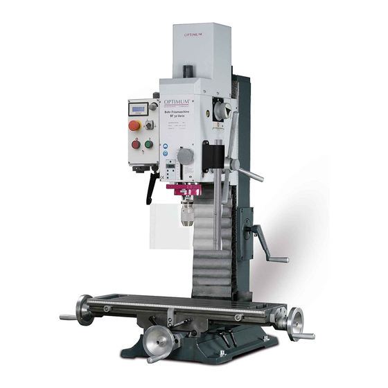
Summary of Contents for Optimum Optimill BF 30V
- Page 1 OPTIMUM M A S C H I N E N - G E R M A N Y Operating manual Version 1.1.5 Drilling-milling machine...
-
Page 2: Table Of Contents
OPTIMUM M A S C H I N E N - G E R M A N Y Table of contents Safety Type plate ..............................5 Safety instructions (warning notes)......................6 1.2.1 Classification of hazards...........................6 1.2.2 Other pictograms ............................7 Intended use .............................7 Reasonably foreseeable misuses......................8... - Page 3 OPTIMUM M A S C H I N E N - G E R M A N Y Operation Safety ..............................26 Control and indicating elements ......................26 4.2.1 Control panel ............................27 Switching on the drilling-milling machine....................28 Switching off the drilling-milling machine....................28 Inserting a tool............................
- Page 4 Dear customer, Thank you very much for purchasing a product made by OPTIMUM. OPTIMUM metal working machines offer a maximum of quality, technically optimum solutions and convince by an outstanding price performance ratio. Continuous enhancements and product innovations guarantee state-of-the-art products and safety at any time.
-
Page 5: Safety
Always keep this documentation close to the drilling-milling machine. INFORMATION If you are unable to solve a problem using these operating instructions, please contact us for advice: Optimum Maschinen Germany GmbH Dr. Robert-Pfleger-Str. 26 D- 96103 Hallstadt Email: info@optimum-maschinen.de... -
Page 6: Safety Instructions (Warning Notes)
OPTIMUM M A S C H I N E N - G E R M A N Y Safety instructions (warning notes) 1.2.1 Classification of hazards We classify the safety warnings into various levels. The table below gives an overview of the classification of symbols (ideogram) and the warning signs for each specific danger and its (possible) consequences. -
Page 7: Other Pictograms
We expressly point out that the guarantee or CE conformity will expire due to any constructive technical or procedural changes which had not been performed by the company Optimum Maschinen Germany GmbH. It is also part of intended use that ... -
Page 8: Reasonably Foreseeable Misuses
OPTIMUM M A S C H I N E N - G E R M A N Y WARNING! Heaviest injuries through improper use. It is forbidden to make any modifications or alterations to the operating values of the drilling-milling machine. These could endanger the staff and cause damage to the drilling-milling machine. - Page 9 We expressly point out that the guarantee will expire due to any constructive technical or proce- dural changes which had not been performed by the company Optimum Maschinen Germany GmbH. With the conversion of the machine BF30Vario an cabinet is required.
-
Page 10: Possible Dangers Caused By The Drilling-Milling Machine
OPTIMUM M A S C H I N E N - G E R M A N Y Possible dangers caused by the drilling-milling machine The drilling-milling machine was built using the latest technological advances. Nonetheless there remains a residual risk, since the drilling-milling machine operates with ... -
Page 11: Operator Positions
OPTIMUM M A S C H I N E N - G E R M A N Y Electrical specialist Due to his professional training, knowledge and experience as well as his knowledge of respec- tive standards and regulations the electrical specialist is able to perform works on the electrical system and to recognise and avoid any possible dangers himself. -
Page 12: Safety Devices
OPTIMUM M A S C H I N E N - G E R M A N Y CAUTION! Risk of fire and explosion by using flammable materials or cooling lubricants. Before processing inflammable materials (e.g. aluminium, magnesium) or using inflammable auxiliary materials (e.g. -
Page 13: Lockable Main Switch
OPTIMUM M A S C H I N E N - G E R M A N Y Activate the emergency stop impact switch only in case of danger! If this push button is actuated in order to switch off the drilling-milling machine in the standard operation the tool or workpiece might get damaged. -
Page 14: Separating Protective Equipment
OPTIMUM M A S C H I N E N - G E R M A N Y 1.9.4 Separating protective equipment Adjust the protective equipment to the correct height before you start working. Clamping screw To do so, detach the clamping screw, adjust the required height and re-tighten the clamping screw. -
Page 15: Personnel Protective Equipment
OPTIMUM M A S C H I N E N - G E R M A N Y 1.11 Personnel protective equipment For certain work personal protective equipment is required. Protect your face and your eyes: Wear a safety helmet with facial protection when performing works where your face and eyes are exposed to hazards. -
Page 16: Switching-Off And Securing The Drilling-Milling Machine
OPTIMUM M A S C H I N E N - G E R M A N Y 1.13 Switching-off and securing the drilling-milling machine Switch off the drilling-milling machine with the main switch before starting any maintenance and repair works. -
Page 17: Technical Data
OPTIMUM M A S C H I N E N - G E R M A N Y Technical data The following information are the dimensions and indications of weight and the manufacturer‘s approved machine data.. Electrical connection Motor 230V / 50Hz / 2.2 kW Drilling-milling capacity Ø... -
Page 18: Environmental Conditions
OPTIMUM M A S C H I N E N - G E R M A N Y Environmental conditions Temperature 5-35 °C Humidity 25 - 80% Operating material Gear filling quantity 1.2 litres Mobilgear 627, ISO VG 100 Viscosity 100 cSt at 40°C or a comparable oil... -
Page 19: Installation Plan Bf30V
OPTIMUM M A S C H I N E N - G E R M A N Y 2.11 Installation plan BF30V Img.2-1: Installation plan BF30V Technical data BF30Vario Version 1.1.5 dated 2015-08-31 Original operating instructions Page 19... -
Page 20: Installation Plan Of Optional Substructure
OPTIMUM M A S C H I N E N - G E R M A N Y 2.12 Installation plan of optional substructure Img.2-2: Installation plan of optional substructure BF30Vario Technical data Page 20 Original operating instructions Version 1.1.5 dated 2015-08-31... -
Page 21: Unpacking And Connecting
OPTIMUM M A S C H I N E N - G E R M A N Y Unpacking and connecting INFORMATION The drilling-milling machine is pre assembled. Scope of delivery Check immediately upon delivery of the drilling-milling machine if there are any transport dam- ages or loosened fastening screws. -
Page 22: Storage
OPTIMUM M A S C H I N E N - G E R M A N Y Storage ATTENTION! In case of wrong and improper storage electrical and mechanical machine components might get damaged and destroyed. Store packed and unpacked parts only under the intended environmental conditions. -
Page 23: Load Suspension Point
OPTIMUM M A S C H I N E N - G E R M A N Y Any parts sticking out such as stops, handles, etc. have to be secured by measures taken by the customer if necessary in order to avoid endangerment of persons. -
Page 24: Power Supply
Risk by using improper tool holders or operating them at inadmissible speeds. Only use the tool holders (e.g. drill chuck) which were delivered with the machine or which are offered as optional equipment by OPTIMUM. Only use tool holders in the intended admissible speed range. -
Page 25: Warming Up The Machine
OPTIMUM M A S C H I N E N - G E R M A N Y 3.5.4 Warming up the machine ATTENTION! If the drilling-milling machine and in particular the milling spindle is immediately operated at maximum load when it is cold it may result in damages. -
Page 26: Safety
OPTIMUM M A S C H I N E N - G E R M A N Y Operation Safety Commission the drilling-milling machine only under the following conditions: The drilling-milling machine is in proper working order. The drilling-milling machine is used as intended. -
Page 27: Control Panel
OPTIMUM M A S C H I N E N - G E R M A N Y 4.2.1 Control panel Img.4-1: Control panel Pos. Designation Pos. Designation Clamping screw of spindle sleeve Digital display speed EMERGENCY-STOP Speed control Push button spindle rotation "ON"... -
Page 28: Switching On The Drilling-Milling Machine
OPTIMUM M A S C H I N E N - G E R M A N Y Rotation direction switch Standard operation, selection left-handed or right-handed rotation. Potentiometer Speed setting "VARIO" Push button ON The push button "ON" switches on the rotation of the spindle. -
Page 29: Inserting A Tool
OPTIMUM M A S C H I N E N - G E R M A N Y Inserting a tool 4.5.1 Installation CAUTION! When milling operations are performed the cone seat must always be fixed to the draw- in rod. All cone connections with the taper bore of the work spindle without using the draw-in rod is not allowed for milling operations. -
Page 30: Clamping The Workpieces
The optimum cutting speed mainly depends on the material and on the material of the tool. With tools (milling cutters) made of hard metal or ceramic insert it is possible to work with higher speeds than with tools made of high-alloy high speed steel (HSS). -
Page 31: Standard Values For Cutting Speeds
OPTIMUM M A S C H I N E N - G E R M A N Y 4.8.1 Standard values for cutting speeds [ m/min ] with high-speed steel and hard metal in upcut milling Tool Steel Grey cast iron... -
Page 32: Standard Values For Speeds With Hss - Eco - Twist Drilling
OPTIMUM M A S C H I N E N - G E R M A N Y 4.8.2 Standard values for speeds with HSS – Eco – twist drilling Cooling Drill diameter Material 5600 3550 2800 2240 2000 1600... -
Page 33: Manual Spindle Sleeve Feed With The Spindle Sleeve Lever
OPTIMUM M A S C H I N E N - G E R M A N Y 4.10 Manual spindle sleeve feed with the spindle sleeve lever ATTENTION! The clutch of the fine feed has to be disengaged before the spindle sleeve lever can be used. -
Page 34: Malfunctions
OPTIMUM M A S C H I N E N - G E R M A N Y (2) converts the measuring unit from millimetres to inches and vice versa. , Value increase in operation mode "S" ... -
Page 35: Swivelling The Drill-Mill Head
OPTIMUM M A S C H I N E N - G E R M A N Y 4.12 Swivelling the drill-mill head The drill-mill head may be swivelled 45° to the right and to the left. Four screwings need to be loosened. -
Page 36: Threading
OPTIMUM M A S C H I N E N - G E R M A N Y 4.13 Threading Img.4-7: Operation mode thread cutting Pos. Designation Pos. Designation Selector switch for reduction stage Speed control Selection switch operating mode Push button spindle rotation "ON"... -
Page 37: Maintenance
OPTIMUM M A S C H I N E N - G E R M A N Y Maintenance In this chapter you will find important information about Inspection Maintenance Repair of the drilling-milling machine. ATTENTION! Properly performed regular maintenance is an essential prerequisite for ... -
Page 38: Inspection And Maintenance
OPTIMUM M A S C H I N E N - G E R M A N Y Inspection and maintenance The type and level of wear depends to a large extent on the individual usage and operating conditions. For this reason, all the intervals are only valid for the authorised conditions. - Page 39 OPTIMUM M A S C H I N E N - G E R M A N Y Interval Where? What? How? For oil change use an appropriate collecting tray of suffi- cient capacity. Have the drilling-milling machine run for a few minutes, the oil will heat up and will slightly penetrate from the opening.
- Page 40 OPTIMUM M A S C H I N E N - G E R M A N Y Interval Where? What? How? Lubricate all slideways. Slideways X axis Every week Oiling Slideways Y axis Slideways Z axis Img.5-3: Slideways ...
- Page 41 OPTIMUM M A S C H I N E N - G E R M A N Y Interval Where? What? How? An extended clearance in the spindles of the cross table can be reduced by readjusting the spindle nuts.
- Page 42 OPTIMUM M A S C H I N E N - G E R M A N Y Interval Where? What? How? Cross table Regulating screw V-ledge X axis right side Regulating screw V-ledge Y axis front Readjusting As required X and Y axis Img.5-7: Cross table...
-
Page 43: Repair
If the repairs are carried out by qualified technical personnel, they must follow the indications given in these operating instructions. Optimum Maschinen Germany GmbH accepts no liability nor does it guarantee against damage and operating malfunctions resulting from failure to observe these operating instructions. - Page 44 OPTIMUM M A S C H I N E N - G E R M A N Y BF30Vario Maintenance Page 44 Original operating instructions Version 1.1.5 dated 2015-08-31...
-
Page 45: Ersatzteile - Spare Parts
OPTIMUM M A S C H I N E N - G E R M A N Y Ersatzteile - Spare parts Säule - Column 13-2 13-1 41-1 41-2 Abb.6-1: Säule-Column Ersatzteile - Spare parts BF30V DE | GB Version 1.1.5 2015-08-31... -
Page 46: Kreuztisch - Cross Table 1 - 2
Kreuztisch - Cross table 1 - 2 68-1 68-2 51-1 51-2 Abb.6-2: Kreuztisch- Cross table 1-2... - Page 47 Kreuztisch - Cross table 2 - 2 106-2 106-1 125 126 106-1 106-2 Abb.6-3: kreuztisch- Cross table 2- 2...
-
Page 48: Schutzeinrichtung - Protection Device
OPTIMUM M A S C H I N E N - G E R M A N Y Schutzeinrichtung - Protection device 145-3 145-5 145-4 145-2 145-1 145-7 145-6 Abb.6-4: Schutzeinrichtung- Protection device DE | GB BF30V Ersatzteile - Spare parts Originalbetriebsanleitung Version 1.1.5 2015-08-31... -
Page 49: Fräskopf - Milling Head 1 - 3
Fräskopf - Milling head 1 - 3 276-1 228-1 217 218 Abb.6-5: Fräskopf- Milling head 1- 3... -
Page 50: Fräskopf - Milling Head 2 - 3
OPTIMUM M A S C H I N E N - G E R M A N Y Fräskopf - Milling head 2 - 3 Abb.6-6: Fräskopf- Milling head 2- 3 DE | GB BF30V Ersatzteile - Spare parts Originalbetriebsanleitung... - Page 51 OPTIMUM M A S C H I N E N - G E R M A N Y Fräskopf - Milling head 3 - 3 384-1 Abb.6-7: Fräskopf- Milling head 3- 3 Ersatzteile - Spare parts BF30V DE | GB Version 1.1.5 2015-08-31...
-
Page 52: Maschinenunterbau (Optional) - Machine Stand (Option)
OPTIMUM M A S C H I N E N - G E R M A N Y Maschinenunterbau (Optional) - Machine stand (option) 411-5 411-4 411-7 412-5 412-1 411-9 411-6 411-1 411-8 412-3 412-4 404-2 412-2 404-3 404-1 406-2... -
Page 53: Maschinenschilder - Machine Labels
OPTIMUM M A S C H I N E N - G E R M A N Y Maschinenschilder - Machine labels Abb.6-9: Maschinenschilder - Machine labels Ersatzteile - Spare parts BF30V DE | GB Version 1.1.5 2015-08-31 Originalbetriebsanleitung... -
Page 54: Maschinenschilder - Machine Labels
OPTIMUM M A S C H I N E N - G E R M A N Y 6.9.1 Maschinenschilder - Machine labels Menge Grösse Artikelnummer Bezeichnung Designation Quan- Size Article no. tity BF30 Vario/ MK3 03338430L01 Frontschild Front label... -
Page 55: Teileliste - Parts List
OPTIMUM M A S C H I N E N - G E R M A N Y 6.10 Teileliste - Parts list Artikel- Menge Grösse Bezeichnung Designation nummer Qty. Size Item no. Säule Column 033384301 Träger Spindelmutter Z-Achse Support spindle nut z axis... - Page 56 OPTIMUM M A S C H I N E N - G E R M A N Y Artikel- Menge Grösse Bezeichnung Designation nummer Qty. Size Item no. Innensechskantschraube Socket head screw GB 70-85 /M8 x 25 0333843069 Federring Lock washer...
- Page 57 OPTIMUM M A S C H I N E N - G E R M A N Y Artikel- Menge Grösse Bezeichnung Designation nummer Qty. Size Item no. Gehäuse Fräskopf Housing milling head 03338430160 Drehlagerbock Fräskopf Turning clevis mounting milling head...
- Page 58 OPTIMUM M A S C H I N E N - G E R M A N Y Artikel- Menge Grösse Bezeichnung Designation nummer Qty. Size Item no. Innensechskant - Stiftschraube Threaded pin GB 78-85/M5 x 16 03338430268 Ölschauglas Oil sight glas...
- Page 59 OPTIMUM M A S C H I N E N - G E R M A N Y Artikel- Menge Grösse Bezeichnung Designation nummer Qty. Size Item no. Innensechskantschraube Socket head screw GB 70-85/ M8 x 25 03338430355 Federring Lock washer...
- Page 60 OPTIMUM M A S C H I N E N - G E R M A N Y Artikel- Menge Grösse Bezeichnung Designation nummer Qty. Size Item no. Schlauchbinder 230V Hose binder 230 V 033520028 411-8 Schlauchbinder 400V Hose binder 400 V...
-
Page 61: Schaltplan - Wiring Diagram
OPTIMUM M A S C H I N E N - G E R M A N Y 6.11 Schaltplan - Wiring diagram Abb.6-10: Schaltplan - Wiring diagram Ersatzteile - Spare parts BF30V DE | GB Version 1.1.5 2015-08-31 Originalbetriebsanleitung... -
Page 62: Teileliste Elektrik - Parts List Electrical Komponents
OPTIMUM M A S C H I N E N - G E R M A N Y 6.11.1 Teileliste Elektrik - Parts list electrical komponents Menge Grösse Artikelnummer Bezeichnung Designation Qty. Size Item no. Hauptschalter Main switch LW8GS-20104-2/660V,20A 03338430376... -
Page 63: Malfunctions
OPTIMUM M A S C H I N E N - G E R M A N Y Malfunctions Malfunctions on the drilling-milling machine Malfunction Cause / possible effects Solution The drilling-milling machine • Power-on sequence ignored. • "Switching on the drilling-mill- does not start ing machine“... -
Page 64: Appendix 8.1 Copyright
OPTIMUM M A S C H I N E N - G E R M A N Y Appendix Copyright This document is copyright. All derived rights are also reserved, especially those of translation, re-printing, use of figures, broadcast, reproduction by photo-mechanical or similar means and recording in data processing systems, neither partial nor total. -
Page 65: Liability Claims For Defects / Warranty
- Non reproducible software errors Any services which OPTIMUM GmbH or one of its agents performs in order to fulfill in the frame of an additional guarantee are neither an acceptance of the defects nor an accept- ance of its obligation to compensate. Such services do neither delay nor interrupt the war- ranty period. -
Page 66: Disposal Of The Packaging Of New Devices
OPTIMUM M A S C H I N E N - G E R M A N Y If applicable remove batteries and accumulators. Disassemble the machine if required into easy-to-handle and reusable assemblies and component parts. ... - Page 67 Modified settings Experiences with the drilling-milling machine, which could be important to other users Recurring failures Optimum Maschinen Germany GmbH Dr.-Robert-Pfleger-Str. 26 D-96103 Hallstadt Fax +49 (0) 951 - 96 555 - 888 Email: info@optimum-maschinen.de Appendix BF30Vario Version 1.1.5 dated 2015-08-31...
- Page 68 M A S C H I N E N - G E R M A N Y EC - Declaration of Conformity Machinery Directive 2006/42/EC Annex II 1.A The manufacturer / Optimum Maschinen Germany GmbH retailer: Dr.-Robert-Pfleger-Str. 26 D- 96103 Hallstadt...
- Page 69 OPTIMUM M A S C H I N E N - G E R M A N Y Index Emissions ............18 Environmental conditions ........ 18 Accessories ............25 Speeds ............17 Assembling ............23 Spindle seat ............. 17 available accessories ..........25 Technical Details Drilling-milling capacity ........
- Page 70 Quellenverzeichnis von Ihrem Fachhändler Metallbau Mehner Optimum Fräsmaschinen und CNC Fräsmaschinen: Optimum OPTImill BF 30V Übersicht OPTImill BF 30V • ◦ OPTImill BF 30V Ersatzteile ◦ OPTImill BF 30V Zubehör CNC OPTImill BF 30V • OPTImill Zubehör • Ihr Ersatzteil nicht in den Listen? Direkt zum >>Formular Download<<.
Need help?
Do you have a question about the Optimill BF 30V and is the answer not in the manual?
Questions and answers